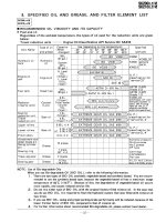
Shop manual máy đào HuynDai R170W-9 (Phần 5) - P5.1
Bạn đang xem bản rút gọn của tài liệu. Xem và tải ngay bản đầy đủ của tài liệu tại đây (428.07 KB, 3 trang )
SECTION 5 MECHATRONICS SYSTEMSECTION 5 MECHATRONICS SYSTEM
Group 1 Outline
-----------------------------------------------------------------------------------------------------------------
5-1
Group 2 Mode Selection System
------------------------------------------------------------------------------------
5-3
Group 3 Automatic Deceleration System
-----------------------------------------------------------------------
5-6
Group 4 Power Boost System
-----------------------------------------------------------------------------------------
5-7
Group 5 Travel Speed Control System
---------------------------------------------------------------------------
5-8
Group 6 Automatic Warming Up System
-----------------------------------------------------------------------
5-9
Group 7 Engine Overheat Prevention System
---------------------------------------------------------------
5-10
Group 8 Variable Power Control System
------------------------------------------------------------------------
5-11
Group 9 Attachment Flow Control System
---------------------------------------------------------------------
5-12
Group 10 Anti-Restart System
-------------------------------------------------------------------------------------------
5-13
Group 11 Self-Diagnostic System
-------------------------------------------------------------------------------------
5-14
Group 12 Engine Control System
-------------------------------------------------------------------------------------
5-27
Group 13 EPPR Valve
--------------------------------------------------------------------------------------------------------
5-28
Group 14 Monitoring System
---------------------------------------------------------------------------------------------
5-33
Group 15 Fuel Warmer System
-----------------------------------------------------------------------------------------
5-56
5-1
The NEW CAPO (Computer Aided Power Optimization) system controls engine and pump mutual
power at an optimum and less fuel consuming state for the selected work by mode selection, auto-
deceleration, power boost function, etc. It monitors machine conditions, for instance, engine speed,
coolant temperature, hydraulic oil temperature, and hydraulic oil pressure, etc.
It consists of a MCU, a cluster, an ECM, EPPR valves, and other components. The MCU and the
cluster protect themselves from over-current and high voltage input, and diagnose malfunctions caused
by short or open circuit in electric system, and display error codes on the cluster.
SECTION 5 MECHATRONICS SYSTEMSECTION 5 MECHATRONICS SYSTEM
GROUP 1 OUTLINEGROUP 1 OUTLINE
NEW CAPO
SYSTEM
Power mode selection (P, S, E)
Work mode selection
User mode system (U)
MCU & cluster protection
Open-short diagnosis & error code display
Machine error & ECM fault code display
Machine condition monitoring
Electric signal monitoring
Mode selection system
Auto deceleration system
Power boost system
Travel control system
Automatic warming up system
Engine overheat prevention system
Variable power control system
Anti-restart system
Self-diagnostic system
Machine monitoring system
One touch deceleration system
Attachment flow control system
1, 2 Speed control system
Auto cruise control system
Creep travel control system
5-2
SYSTEM DIAGRAMSYSTEM DIAGRAM
Main pump
Pilot pump
Engine
ECM
CAN 1
MCV
RH control
lever
LH control
lever
One touch
decel button
Power max
button
Horn button
Option
button
N1
pressure
N2
pressure
Work
pressure
Travel
pressure
Attachment
pressure
Attachment
conflux
Attachment
safety
Creep travel
Power max
Arm regen cut
Attachment pilot
pressure
EPPR VALVE
Boom priority
Attachment
MCU
P1
pressure
P2
pressure
P1 P2
P3
P3
pressure
Overload
pressure
sensor
SL SR
Swing
pressure
AO AI
Arm in/out
& Bucket in
pressure
BI
Boom up
pressure
BU
Accel dial
Switch signal
Work tool
Cluster
Serial communication(+)
Serial communication(-)
Pressure signal
Pressure signal
Pressure signal
Drive signal
Pressure signal
Signal
Drive signal
Normal
CN-16
Emergency
CN-16A
CN-16B
Pump power
shift EPPR
Boom cylinder
Shuttle
block
Option B
Arm 1
Boom 2
Swing
Bucket
Arm 2
Option A &
Arm regen
Boom 1
Option C
Dozer
Travel
Dozer
pressure
Travel control valve
Transmisasion
oil pressure
Brake supply valve
Brake oil
pressure
Rear view camera
4
SOLENOID VALVE
Ram lock
Switch signal
Pressure signal
Pressure signal
Accel dial signal
Switch signal
MTCU
CAN 2
Speed sensor
Creep switch
Ram lock switch
TO
O
N
O
FF
Switch signal
P
W
T
Select switch 2
Auto cruise
N
F
R
I
II
RH multifunction sw
Auto cruise switch
14W95MS01