surface modeling Creo
Bạn đang xem bản rút gọn của tài liệu. Xem và tải ngay bản đầy đủ của tài liệu tại đây (1.96 MB, 46 trang )
13
Surface Modeling
Learning Objectives
After completing this chapter you will be able to:
• Create an Extruded Surface.
• Create a Revolved Surface.
• Create a Sweep Surface.
• Create a Blended Surface.
• Create a Swept Blend Surface.
• Create a Helical Sweep Surface.
• Create a Surface by Blending the Boundaries.
• Create a Surface using Variable Section Sweep.
• Create surfaces using Style environment.
• Understand surface editing tools.
Logon
www.cadcim.com
Chapter for free download. L
ogon to www
.cadcim.com for more information
Chapter
13-2
Pro/ENGINEER Wildfire for Designers: F09/04
SURFACE MODELING
Logon
www.cadcim.com
Chapter for free download. L
ogon to www
.cadcim.com for more information
Surface models are a type of three-dimensional (3D) models with no thickness. These models
are widely used in industries like automobile, aerospace, plastic, medical, and so on.
Surface models should not be confused with thick models, that is, models having mass properties.
Surface models do not have thickness whereas thick or solid models have a user-defined thickness.
In Pro/ENGINEER, the surface modeling techniques and feature creation tools are the same as
that used in solid modeling. A solid model of any shape that is created can also be created using
the surface modeling techniques. The only difference between the solid model and the surface
model will be that the solid model will have mass properties but the surface model will not.
Sometimes, complex shapes are difficult to create using solid modeling. Such models can be
easily created using surface modeling and then the surface model can be converted into the
solid model. It becomes easy for a person to learn surface modeling if he is familiar with solid
modeling feature creation tools.
CREATING SURFACES IN Pro/ENGINEER WILDFIRE 2.0
In Pro/ENGINEER Wildfire 2.0, a sketch can be toggled between a solid model and a surface
model. The two tool buttons that are used to toggle between the solid feature and a surface
feature are available on dashboards.
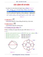
Creating an Extruded Surface
To create an extruded surface, choose the Extrude Tool button from the Base Features
toolbar. The Extrude dashboard is displayed as shown in Figure 13-1.
Figure 13-1 The Extrude dashboard
In this dashboard, the Extrude as solid button is selected by default. Select the
Extrude as surface button to extrude the sketch and create a surface model. All the
attributes that are related to a solid model and that were discussed in Chapter 3 are same
for a surface model also. Some examples of these attributes are sketch plane, both-side or
one-side extrusion, depth of extrusion, and so on.
A surface model can be extruded with capped ends or with open ends. Figure 13-2 shows the
open end surface model and Figure 13-3 shows the capped end surface model. Remember
that to create the capped end surface model, the sketch should be a closed loop. Otherwise,
a surface can be created with the open sketch.
To create a surface with capped ends, select the Capped Ends check box in the Options slide
up panel.
13-3
Figure 13-2 Surface with open ends
Figure 13-3 Surface with capped ends
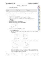
Creating a Revolved Surface
To create a revolved surface, choose the Revolve Tool button from the Base Features toolbar.
The Revolve dashboard is displayed as shown in Figure 13-4. This feature creation tool works in
the same way as in the case of solid modeling.
Figure 13-4 The Revolve dashboard
The Revolve as solid button is selected by default; choose the Revolve as surface
button to create a revolve surface. You can create a revolved capped end surface or an
open end surface. The Capped End check box in the Options slide-up panel is
available only when the sketch is closed and the angle of revolution is less than
360-degrees. Figure 13-5 shows the open end revolve surface and Figure 13-6 shows the capped
end revolve surface.
Figure 13-5 Revolved surface with open ends
Figure 13-6 Revolved surface with capped ends
Logon
www.cadcim.com
Chapter for free download. L
ogon to www
.cadcim.com for more information
Surface Modeling
13-4
Pro/ENGINEER Wildfire for Designers: F09/04
Logon
www.cadcim.com
Chapter for free download. L
ogon to www
.cadcim.com for more information
Creating a Sweep Surface
To create a sweep surface feature, choose Insert > Sweep > Surface from the menu bar. The
SWEEP TRAJ menu is displayed. The method to create a surface sweep feature is the same as
that to create a solid sweep feature. To create a solid sweep feature, refer to Chapter 7. The
additional option of capping the ends that were available in the Extrude and Revolve options is
also available in the Sweep option.
Figures 13-7 and 13-8 show the sweep surfaces with the open and closed ends respectively.
Figure 13-7 Sweep surface with open ends
created using a closed sketch
Figure 13-8 Sweep surface with capped ends created
using a closed sketch
Creating a Blended Surface
To create a surface blend, choose Insert > Blend > Surface from the menu bar. The BLEND
OPTS menu is displayed. The method to create a blended surface is the same as that to create a
solid blend. To create a solid blend feature, refer to Chapter 7. Blended surfaces can be with
open ends or capped ends. Figure 13-9 shows the blended surface with open ends and Figure 13-10
shows the blended surface with capped ends.
Figure 13-9 Blended surface with open ends
Figure 13-10 Blended surface with capped ends
Surface Modeling
13-5
To create a swept blend surface, choose Insert > Swept Blend > Surface from the menu bar.
The BLEND OPTS menu is displayed. The method to create a swept blend surface is the same
that to create a solid swept blend feature. To create a solid swept blend feature, refer to Chapter 8.
Figure 13-11 shows the swept blend with open ends and Figure 13-12 shows the swept blend with
capped ends.
Figure 13-11 Swept blend surface with open
ends
Figure 13-12 Swept blend surface with capped ends
Creating a Helical Sweep Surface
To create a surface helical sweep, choose Insert > Helical Sweep > Surface from the menu bar.
The Surface dialog box and the ATTRIBUTES menu is displayed. The method to create a
helical sweep surface feature is the same as that to create a solid helical sweep feature. For more
information on creating solid helical sweep features, refer to Chapter 8. Figure 13-13 shows the
helical sweep surface with open ends and Figure 13-14 shows the helical sweep surface with
capped ends.
Tip: If you want to create a surface blend with capped end, you need to create a closed
sketch. Pro/ENGINEER does not accept an open sketch for a capped end blend surface.
To create a surface blend with capped ends and keeping the sketch open can also be
done. For this purpose, select the Open Ends option and then draw an open sketch.
Give the blend depth and create the blended surface. Now, redefine the surface feature
and modify the open ends attribute to capped ends. Choose OK from the SURFACE
dialog box. The blended surface with the capped ends is created. This is also true with
other features like extrude, revolve, sweep, and so on.
Creating a Surface by Blending the Boundaries
To create a surface by blending the boundaries, datum curves, or points, choose the
Boundary Blend Tool button from the Base Features toolbar. The Boundary Blend
dashboard is displayed as shown in Figure 13-15 and you are prompted to select
Logon
www.cadcim.com
Chapter for free download. L
ogon to www
.cadcim.com for more information
Creating a Swept Blend Surface
Logon
www.cadcim.com
Chapter for free download. L
ogon to www
.cadcim.com for more information
13-6
Pro/ENGINEER Wildfire for Designers: F09/04
Figure 13-13 Helical sweep surface with open
ends created using an open sketch
Figure 13-14 Helical sweep feature with capped
ends created using the closed sketch
two or more curve chains to define a blended surface. The use of this dashboard are discussed
next.
Figure 13-15 The Boundary Blend dashboard
Curves tab
When you choose the Curves tab, the slide-up panel is displayed. Choose a curve from the
graphics window; the curve is highlighted in red as shown in Figure 13-16. At the two ends of
the curve, T=0 is displayed, an arrow is attached to the curve. When you modify the value of T,
which is by default 0, to some higher value then the curve is extended from that end. Press
CTRL+left mouse button to select the second curve; the second curve also gets highlighted.
Both the selected curves are numbered as per the sequence of selection. The surface is created as
shown in Figure 13-17.
Figure 13-16 Curves selected to blend
Figure 13-17 Boundary blend surface
Surface Modeling
13-7
Now, invoke the Curves slide-up panel and select 2 Chain from the First direction collector;
the slide-up panel is displayed as shown in Figure 13-18. In the slide-up panel, the Move up
and Move down buttons are available, which can change the order of selection of the curves.
The Closed blend check box is used to close the surfaces.
Figure 13-18 Curves slide-up panel
Tip: To delete the curves from the collector, right-click the collector and choose the
Remove all option from the shortcut menu that is displayed.
Figure 13-19 shows the surface created after selecting the three curves and Figure 13-20 shows
the surface that is closed by selecting the Closed blend check box.
Figure 13-19 Surface created after selecting the
curves
Figure 13-20 Surface created after closing it
The Second direction collector in the Curves slide up panel is used to select curves in the
second direction. The second direction curves are usually drawn in a direction other than that
of the first direction. The Figure 13-21 shows the first and second direction curves and
Figure 13-22 shows the surface created after selecting the curves shown in Figure 13-21.
Logon
www.cadcim.com
Chapter for free download. L
ogon to www
.cadcim.com for more information
The collector present below the Curves tab shows 2 Chains. This collector represents the Curves
tab and the number of curves selected in the first direction are displayed in this collector.
Logon
www.cadcim.com
Chapter for free download. L
ogon to www
.cadcim.com for more information
13-8
Pro/ENGINEER Wildfire for Designers: F09/04
Figure 13-21 Datum curves
Figure 13-22 Surface created by selecting the curves
in two directions
Creating a Surface Using Variable Section Sweep
To create a surface by variable section sweep, choose Insert > Variable Section Sweep from the
menu bar. The Variable Section Sweep dashboard is displayed. To learn more about Variable
Section Sweep, refer to Chapter 8. The procedure to create a variable section sweep feature or
surface is the same as was discussed in Chapter 8.
Figure 13-23 shows the trajectories and section that are used to create the variable section
sweep surface. You have an option to keep the ends open or capped. This option is available
in the Options slide-up panel.
Figure 13-23 Variable section sweep surface with open ends
Surface Modeling
13-9
Style is an environment available in Pro/ENGINEER that is used to draw free style curves and
create surfaces by joining them. The surfaces created using the Style environment are called
Super features. This is because these features can contain any number of curves or surfaces.
The Style surfaces can be joined with the Pro/ENGINEER surfaces. They can have the
parent-child relationship among themselves and as well as with Pro/ENGINEER features.
To enter the Style environment, choose the Style Tool available in the Base Features
toolbar or choose Insert > Style from the menu bar. Figure 13-24 shows the appearance
of the Style environment.
Figure 13-24 Style environment
Style Tools Toolbar
Figure 13-25 shows the Style Tools toolbar available in the Style environment. The tools
available in this toolbar are discussed next.
Select Button
This button is used to select the surfaces, curves, planes, and so on in the Style
environment. If you are in middle of a feature creation tool you can choose the Select
button to exit that tool.
Logon
www.cadcim.com
Chapter for free download. L
ogon to www
.cadcim.com for more information
CREATING SURFACES USING STYLE ENVIRONMENT OF
Pro/ENGINEER WILDFIRE 2.0
Logon
www.cadcim.com
Chapter for free download. L
ogon to www
.cadcim.com for more information
13-10
Pro/ENGINEER Wildfire for Designers: F09/04
Figure 13-25 Style Tools toolbar
Set the active datum plane Button
This button is used to select the datum plane on which the drawing or the editing
operation needs to be performed. The datum plane that you select is highlighted by a
mesh.
Create Internal Datum Plane Button
This button is chosen by selecting the black arrow on the right of the Set the active
datum plane button. When you select the arrow, the flyout is displayed. Choose the
Create Internal Datum Plane button to create an internal datum plane in the Style
environment. When you choose this button the DATUM PLANE dialog box is displayed. This
dialog box is used to create a datum plane in a similar procedure that was discussed in Chapter 4.
The datum planes are named as DTM1, DTM2, and so on.
It should be noted that the datum planes created using this button are displayed in the graphics
window only when you are in the Style environment. Once you exit the Style environment, the
datum plane becomes invisible. Any feature created in the Style environment is displayed in the
Model Tree as a Style feature.
Create Curves Button
This button is used to draw curves. When you choose this button, the Curve dashboard
is displayed as shown in Figure 13-26.
Figure 13-26 The Curve dashboard
The options in this dashboard are discussed next.
13-11
Free Radio Button
When the Curve dashboard is displayed, the Free radio button is selected by default. The
prompt in the Message Area reads “Click to define points for the curve (SHIFT to snap)”.
To create curve, click on the screen. A yellow point is displayed at the location where you
clicked. Now, again click to define the second point of the curve. The two points are
joined. When you click to define the location of the third point, you will notice that the
curve that you are drawing is defined by a spline. After defining the points, press the
middle mouse button to create the curve. While specifying a point if you press the SHIFT
key then the point is snapped to the entity already present on the screen.
Remember that the curve drawn using the Free option is created on the active datum plane.
To draw a 3D curve you need to snap the point on the existing entity. You can also draw a 3D
curve by choosing the Toggle showing all views and one view full-size button from the
Style toolbar. When you choose this button, the display is turned into four windows. In
Pro/ENGINEER, this type of display is called a 4-view display mode. The four views show
the top, default, right-side, and front views. You can select a point in one window and then
select the second point in the other window. By specifying points in different windows, the
3D curve can be drawn. To switch back to the single window display mode, choose the
Toggle showing all views and one view full-size button.
Tip: To undo the last operation, choose the Undo button from the Style toolbar. The
shortcut for undo is CTRL+Z.
Planar Radio Button
This radio button when selected allows you to create the curve on the datum plane that is
highlighted by the mesh. This datum plane is called the active plane. The active plane can
be selected before invoking the Curve dashboard by choosing the Set the active datum
plane button.
Tip: Using the Planar option, you can project a point of an existing entity on the
active datum plane. This can be done by selecting the point on the entity using the
SHIFT key. The selected point is projected on the active datum plane.
COS Radio Button
This radio button is used to draw curves on surfaces. The points that you define on a surface
are constrained to that surface. When you click to define the location of the first point of the
curve, the point is placed. Now, this surface is selected and the points placed hereafter
should lie on the same surface. If you click outside this surface then the point is not placed
on the surface. After the curve is drawn, press the middle mouse button. The red curve is
converted to a white curve indicating that the curve is completed. The curve drawn on the
surface is the child of the surface.
Control Points Check Box
While drawing the curve, if this check box is selected, then while editing the curve the
control points are displayed.
Logon
www.cadcim.com
Chapter for free download. L
ogon to www
.cadcim.com for more information
Surface Modeling
13-12
Pro/ENGINEER Wildfire for Designers: F09/04
Logon
www.cadcim.com
Chapter for free download. L
ogon to www
.cadcim.com for more information
Edit curves Button
This button is used to edit the curves that are created as style features. When you choose
this button the Edit curve dashboard is displayed and you are prompted to select a
curve. When you select a curve to edit, the Edit curve dashboard appears as shown in
Figure 13-27.
Figure 13-27 The Edit curve dashboard
The options in the Edit curve dashboard are discussed next.
Curve collector
When you select a curve to edit, the id of the curve is displayed in this collector.
Free radio button
If the curve that is selected for editing was drawn using the Free option, then this radio
button is selected by default.
Planar radio button
If the curve that is selected for editing was drawn using the Planar option, then this
radio button is selected by default.
COS radio button
If the curve that is selected for editing was drawn using the COS option, then this radio
button is selected by default.
Proportional Update check box
If the curve that is selected for editing was drawn using the Proportional Update option,
then the curve is edited proportionately with the points.
Control Points check box
If the curve that is selected for editing was drawn using the Control Points option, then
the control points are displayed on the curve. Using these control points you can modify
the shape of the curve.
Tip: Using the Free option, you can draw a curve on a surface. To draw a curve on
a surface, press SHIFT to select a point on the surface. The surface is highlighted as
you select a point on it and then the point is placed on the surface. This method of
selecting points on a surface can be used to draw curves that join points on two
separate surfaces.
Shortcut menu options
When the control point, next to the endpoint of the curve is selected, the tangent vector of
the curve is highlighted in yellow color. Right-click the yellow vector to display the shortcut
menu, as shown in Figure 13-28.
13-13
Figure 13-28 Shortcut menu
By default, a curve has a natural contact with the adjacent surface. This is evident from the
check mark on the left of the Natural option in the shortcut menu. Figure 13-29 shows the
curve that is connected to the adjacent surface using the Natural option. The curve is drawn
using the Free option. The point on the cylindrical surface is selected by using SHIFT+left
mouse button and similarly another point is selected on the surface at the base. Figure 13-30
shows the curve whose contact type is changed to the Surface Tangent option by choosing
it from the shortcut menu.
Figure 13-29 Curve joining the two surfaces
Figure 13-30 Curve joining the base surface
tangentially
Creating COS’s by projecting curves onto surfaces Button
Using this button, a curve created in the Style environment can be projected onto the
selected surface.
To create COS’s, choose the Create COS’s by projecting curves onto surfaces button from the
Style Tools toolbar. You are prompted to select the surface on which you need to drop the curve.
Select the surface and press the middle mouse button. You are prompted to select the curve that
Logon
www.cadcim.com
Chapter for free download. L
ogon to www
.cadcim.com for more information
Surface Modeling
13-14
Pro/ENGINEER Wildfire for Designers: F09/04
Logon
www.cadcim.com
Chapter for free download. L
ogon to www
.cadcim.com for more information
you need to drop. After selecting the curve, press the middle mouse button. Now, you are
prompted to select the plane normal to which the curve will drop. Select the plane normal to
which the curve will be projected and exit the dashboard.
Create surfaces from boundary curves Button
This button is used to create a surface among a closed boundary of curves. When you
choose this button the Boundary Surfaces dashboard is displayed and you are prompted
to select three or four boundary curves to define a surface. Select the four curves as
shown in Figure 13-31. After selecting the four curves, press the middle mouse button. The
surface is created as shown in Figure 13-32.
Figure 13-31 Four curves
Figure 13-32 Surface created using the curves
Connect surfaces Button
When you choose this button, the Connect surfaces dashboard is displayed and you are
prompted to select the two surfaces. The Style surface can be connected to the
Pro/ENGINEER surface. When you select the two surfaces shown in Figure 13-33 and
press the middle mouse button, the connections are automatically applied to the two surfaces.
These connections may be of two types: curvature connection represented by a dashed line
and the tangent connection represented by an arrow. If the tangent connection is applied
then the arrow is displayed and if the curvature connection is applied then a dashed line is
displayed on the surfaces. Figure 13-34 shows the two surfaces where the tangent connection
is applied and is not applied.
13-15
Figure 13-33 The two surfaces
Figure 13-34 Arrow and the dashed line
After surfaces are selected, the Connect surfaces dashboard is displayed as shown in Figure 13-35.
To apply the connection, click on any one end of the dashed line. The dashed line is converted
to an arrow, indicating that the two surfaces are connected. To remove the connection, use
SHIFT+left click on the arrow.
Figure 13-35 The Connect surfaces dashboard
Figure 13-36 shows the style surface when the type connection is curvature and Figure 13-37
shows the surface when it is connected tangentially.
Figure 13-36 Surface connected at the top by
curvature connection
Figure 13-37 Surface connected at the top by
tangent connection
Logon
www.cadcim.com
Chapter for free download. L
ogon to www
.cadcim.com for more information
Surface Modeling
13-16
Pro/ENGINEER Wildfire for Designers: F09/04
Logon
www.cadcim.com
Chapter for free download. L
ogon to www
.cadcim.com for more information
Note
The Icon Length dimension box on the Connect surfaces dashboard is used to increase the
length of the arrow and the dashed line.
To delete a curve, select the curve and when it turns red in color, press the DELETE key.
Trim selected quilts Button
This button is used to trim a surface. When you choose this button, the Trim dashboard
is displayed and you are prompted to select the surface(s) to trim. Select the surface so
that it turns pink in color and then press the middle mouse button. Now, you are
prompted to select the curve that will be used to trim the surface. Select the curve and press the
middle mouse button. The selected surface is highlighted in two portions. Select the portion to
delete. Choose the green check mark to exit the trim tool.
Figure 13-38 shows the surface and the curve that are selected for trimming. This figure also
shows the surface divided into two portions. The portion defined by the curve is selected to
delete. Figure 13-39 shows the surface after trimming.
Figure 13-38 Surface is divided into two portions
Figure 13-39 Surface after trimming
Note
After completing the Style feature creation, choose the Exit the current Style feature button to
exit the Style environment.
SURFACE EDITING TOOLS IN Pro/ENGINEER WILDFIRE
The surface editing tools help in decreasing the modeling time. They also help in creating
complex surface models. The surface editing tools that you will be learning in the next section
are as follows:
1.
2.
3.
4.
Mirror
Merge
Trim
Fill
5.
6.
7.
8.
Intersect
Offset
Thicken
Solidify
9. Vertex Round
Surface Modeling
13-17
The Mirror Tool is used to mirror the surface about a plane. This tool is available in the
Edit Features toolbar only when a surface is selected. When you choose this button, the
Mirror dashboard is displayed as shown in Figure 13-40.
Figure 13-40 The Mirror dashboard
Using the References tab you can choose the mirroring plane. The Copy as Dependent check
box is selected by default in the Options tab. The makes sure that the Parent-child relationship
is maintained between the mirrored and the original surface. Figure 13-41 shows the mirror
plane about which the surface is mirrored as shown in Figure 13-42.
Figure 13-41 Mirror plane and the surface to
be mirrored
Figure 13-42 Surfaces after mirroring and
keeping the original surface
Merging the Surfaces
The Merge Tool is used to merge the two surfaces and make them a single surface. A
surface is also known as a Quilt. To convert a surface to a solid, it is necessary that the
surfaces are merged. While merging the surfaces, this tool also trims the surfaces. This
tool is available in the Edit Features toolbar only when the two surfaces to be merged are
selected. When you choose the Merge Tool button, the Merge dashboard is displayed as shown
in Figure 13-43.
Figure 13-43 The Merge dashboard
The following steps explain the procedure to merge the surfaces shown in Figure 13-44.
1. Select the Quilts option from the Filter drop-down list. Select the two surfaces and when the
surfaces turn pink in color, choose the Merge Tool; the Merge dashboard is displayed. In
Logon
www.cadcim.com
Chapter for free download. L
ogon to www
.cadcim.com for more information
Mirroring the Surfaces
13-18
Pro/ENGINEER Wildfire for Designers: F09/04
Logon
www.cadcim.com
Chapter for free download. L
ogon to www
.cadcim.com for more information
this figure, the part of the surfaces that will be retained after the two surfaces are merged is
highlighted by yellow dots on it. The yellow arrows points to show the side of the surface to
keep. The direction of yellow arrow can be toggled by using the Change side of first quilt to
keep and the Change side of second quilt to keep buttons available on the Merge dashboard.
2. Choose the Change side of first quilt to keep button and then choose the Change side of
second quilt to keep button. Notice that the outer side of the surfaces are highlighted with
yellow dots as shown in Figure 13-45.
Figure 13-44 Two surfaces to merge
Figure 13-45 Arrows showing the part of the surface
to retain
3. Choose the Preview button and then exit the dashboard. The resulting merged surface is
shown in Figure 13-46. This merged surface is a single surface and now can be converted to
a solid feature.
Figure 13-46 Merged surface
The Reference tab of the Merge dashboard shows the selected quilts. In the Options tab, you
can select between Intersect and Join options. The Join option can be used when the edge of
one quilt lies on the other quilt.
Surface Modeling
13-19
As the name suggests, the Trim Tool is used to trim the selected surfaces using a
trimming object. You need to select the surface that you need to trim and then choose
the Trim Tool button from the Edit Features toolbar. The Trim dashboard is displayed,
as shown in Figure 13-47. You are prompted to select the trimming object. This trimming object
can be a curve, plane, edge, or a surface.
Figure 13-47 the Trim dashboard
The part of the surface that is to be retained is highlighted with yellow dots. A yellow arrow
points in the direction of the surface to be retained after trimming. You can choose the Flip
between one side, other side, or both sides of trimmed surface to keep button to toggle
the direction of yellow arrow. By default, the trimming object is deleted after the surfaces are
trimmed. If you need to keep the trimming object, select the Keep trimming surface check box
from the Options slide-up panel.
Figure 13-48 shows the surface selected as the trimming object, the trimming surface, and the
yellow arrow. From this figure it is evident that the arrow is pointing toward the right; therefore
the right portion of the surface will be retained after trimming. Figure 13-49 shows the surface
obtained after trimming.
Figure 13-48 Trimming surfaces
Figure 13-49 Surface obtained after trimming
Creating the Fill Surfaces
The Fill option is used to create a planar surface by sketching its boundaries. When you choose
this option from the Edit menu in the menu bar, the Fill dashboard is displayed as shown in
Figure 13-50.
Figure 13-50 The Fill dashboard
Logon
www.cadcim.com
Chapter for free download. L
ogon to www
.cadcim.com for more information
Trimming the Surfaces
13-20
Pro/ENGINEER Wildfire for Designers: F09/04
Logon
www.cadcim.com
Chapter for free download. L
ogon to www
.cadcim.com for more information
From the References slide-up panel choose the Define button to select the sketching plane and
drawing the sketch. Figure 13-51 shows the sketch plane and Figure 13-52 shows the surface that
is created using the Fill option.
Figure 13-51 The sketch plane for creating a fill
surface
Figure 13-52 Fill surface
Creating the Intersect Curves
The Intersect option is used to create a curve at the intersection of two surfaces. The intersect
curve can then be used for various purposes. The Intersect option is available in the Edit menu
only when you have selected a surface. When you choose this option from the Edit menu, the
Intersect dashboard is displayed as shown in Figure 13-53.
Figure 13-53 The Intersect dashboard
When you select the second surface, the intersecting curve is created as shown in Figure 13-54.
Make sure to select the second surface while holding the CTRL key down. The curve created can
Figure 13-54 Surfaces selected to create the intersecting curve