settings menu set
Bạn đang xem bản rút gọn của tài liệu. Xem và tải ngay bản đầy đủ của tài liệu tại đây (711.4 KB, 52 trang )
20
Settings menu SEt-
(1)In corresponds to the nominal drive current indicated in the Installation Manual and on the drive rating plate.
(2)Caution: These settings are not related to the "automatic standstill DC injection" function.
Code Description Adjustment
range
Factory setting
ItH Motor thermal protection - max. thermal current 0.2 to 1.5 In (1) According to drive
rating
Set ItH to the nominal current on the motor rating plate.
Please refer to OLL on page 68
if you wish to suppress thermal protection.
UFr IR compensation/voltage boost 0 to 100% 20
- For UFt (page 24
) = n or nLd: IR compensation
- For UFt = L or P: Voltage boost
Used to optimize the torque at very low speed (increase UFr if the torque is insufficient).
Check that the value of UFr is not too high for when the motor is warm (risk of instability).
Modifying UFt (page 24
) will cause UFr to return to the factory setting (20%).
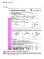
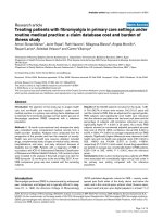
FLG Frequency loop gain 1 to 100% 20
Parameter can only be accessed if UFt (page 24
) = n or nLd.
The FLG parameter adjusts the drive’s ability to follow the speed ramp based on the inertia of the machine
being driven.
Too high a gain may result in operating instability.
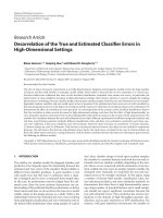
StA Frequency loop stability 1 to 100% 20
Parameter can only be accessed if UFt (page 24
) = n or nLd.
Used to adapt the return to steady state after a speed transient (acceleration or deceleration), according to
the dynamics of the machine.
Gradually increase the stability to avoid any overspeed.
SLP Slip compensation 0 to 150% 100
Parameter can only be accessed if UFt (page 24
) = n or nLd.
Used to adjust the slip compensation value fixed by nominal motor speed.
The speeds given on motor rating plates are not necessarily exact.
• If slip setting < actual slip: the motor is not rotating at the correct speed in steady state.
• If slip setting > actual slip: the motor is overcompensated and the speed is unstable.
IdC Level of DC injection braking current activated
via logic input or selected as stop mode (2).
See page 46 0 to In (1) 0.7 In (1)
tdC Total DC injection braking time selected as stop
mode (2).
See page 46 0.1 to 30 s 0.5 s
tdC1 Automatic standstill DC injection time See page 47 0.1 to 30 s 0.5 s
SdC1 Level of automatic standstill DC injection current See page 47 0 to 1.2 In (1) 0.7 In (1)
tdC2 2
nd
automatic standstill DC injection time See page 47 0 to 30 s 0 s
SdC2 2
nd
level of standstill DC injection current See page 47 0 to 1.2 In (1) 0.5 In (1)
These parameters only appear if the corresponding function has been selected in another menu. When the corresponding
function is also accessible and adjustable from within the configuration menu, to aid programming their description is detailed
in these menus, on the pages indicated.
Those which are underlined appear in factory settings mode.
SEt-
0 0.1 0.2 0.3 0.4 0.5
-10
10
20
30
40
0
50
0 0.1 0.2 0.3 0.4 0.5
-10
10
20
30
40
0
50
0 0.1 0.2 0.3 0.4 0.5
-10
10
20
30
40
0
50
t
Hz
t
Hz
t
Hz
FLG low
FLG correct
FLG high
In this case,
increase FLG
In this case,
reduce FLG
0 0.1 0.2 0.3 0.4 0.5 t
-10
10
20
30
40
0
50
Hz
0 0.1 0.2 0.3 0.4 0.5 t
-10
10
20
30
40
0
50
Hz
0 0.1 0.2 0.3 0.4 0.5 t
-10
10
20
30
40
0
50
Hz
StA low
StA correct
StA high
In this case,
increase StA
In this case,
reduce StA
21
Settings menu SEt-
(1)In corresponds to the nominal drive current indicated in the Installation Manual and on the drive rating plate.
Code Description Adjustment
range
Factory setting
JPF Skip frequency 0 to 500 0 Hz
Prevents prolonged operation at a frequency range of ± 1 Hz around JPF. This function prevents a critical
speed which leads to resonance. Setting the function to 0 renders it inactive.
JF2 2
nd
skip frequency 0 to 500 0 Hz
Prevents prolonged operation at a frequency range of ± 1 Hz around JF2. This function prevents a critical
speed which leads to resonance. Setting the function to 0 renders it inactive.
JGF Jog operating frequency See page 52 0 to 10 Hz 10 Hz
rPG PI regulator proportional gain See page 57 0.01 to 100 1
rIG PI regulator integral gain See page 57 0.01 to 100/s 1/s
FbS PI feedback multiplication coefficient See page 57 0.1 to 100 1
PIC Reversal of the direction of correction of the PI
regulator
See page 57 nO - YES nO
rP2 2
nd
preset PI reference See page 57 0 to 100% 30%
rP3 3
rd
preset PI reference See page 57 0 to 100% 60%
rP4 4
th
preset PI reference See page 57 0 to 100% 90%
SP2 2
nd
preset speed See page 51 0 to 500 Hz 10 Hz
SP3 3
rd
preset speed See page 51 0 to 500 Hz 15 Hz
SP4 4
th
preset speed See page 51 0 to 500 Hz 20 Hz
SP5 5
th
preset speed See page 51 0 to 500 Hz 25 Hz
SP6 6
th
preset speed See page 51 0 to 500 Hz 30 Hz
SP7 7
th
preset speed See page 51 0 to 500 Hz 35 Hz
SP8 8
th
preset speed See page 51 0 to 500 Hz 40 Hz
SP9 9
th
preset speed See page 51 0 to 500 Hz 45 Hz
SP10 10
th
preset speed See page 51 0 to 500 Hz 50 Hz
SP11 11
th
preset speed See page 51 0 to 500 Hz 55 HZ
SP12 12
th
preset speed See page 51 0 to 500 Hz 60 Hz
SP13 13
th
preset speed See page 51 0 to 500 Hz 70 Hz
SP14 14
th
preset speed See page 51 0 to 500 Hz 80 Hz
SP15 15
th
preset speed See page 51 0 to 500 Hz 90 Hz
SP16 16
th
preset speed See page 51 0 to 500 Hz 100 Hz
CLI Current limit 0.25 to 1.5 In (1) 1.5 In (1)
Used to limit the torque and the temperature rise of the motor.
CL2 2
nd
current limit See page 61 0.25 to 1.5 In (1) 1.5 In (1)
tLS Low speed operating time 0 to 999.9 s 0 (no time limit)
Following operation at LSP for a defined period, a motor stop is requested automatically. The motor restarts
if the frequency reference is greater than LSP and if a run command is still present.
Caution: Value 0 corresponds to an unlimited time
rSL Restart error threshold ("wake-up" threshold) See page 58 0 to 100% 0
UFr2 IR compensation, motor 2 See page 63 0 to 100% 20
FLG2 Frequency loop gain, motor 2 See page 63 1 to 100% 20
StA2 Stability, motor 2 See page 63 1 to 100% 20
SLP2 Slip compensation, motor 2 See page 63 0 to 150% 100%
These parameters only appear if the corresponding function has been selected in another menu. When the corresponding
function is also accessible and adjustable from within the configuration menu, to aid programming their description is detailed
in these menus, on the pages indicated.
Those which are underlined appear in factory settings mode.
SEt-
22
Settings menu SEt-
(1)In corresponds to the nominal drive current indicated in the Installation Manual and on the drive rating plate.
Code Description Adjustment
range
Factory setting
Ftd Motor frequency threshold above which the relay contact
(R1 or R2 = FtA) closes or output AOV = 10 V (dO = StA)
0 to 500 Hz bFr
ttd Motor thermal state threshold above which the relay contact (R1
or R2 = tSA) closes or output AOV = 10 V (dO = tSA)
0 to 118% 100%
Ctd Motor current threshold beyond which the relay contact
(R1 or R2 = CtA) closes or output AOV = 10 V (dO = CtA)
0 to 1.5 In (1) In (1)
SdS Scale factor for display parameter SPd1/SPd2/SPd3 (SUP-
menu on page 72
)
0.1 to 200 30
Used to scale a value in proportion to the output frequency rFr: the machine speed, the motor speed, etc.
- If SdS
y
1, SPd1 is displayed (possible definition = 0.01)
- If 1 < SdS
y
10, SPd2 is displayed (possible definition = 0.1)
- If SdS > 10, SPd3 is displayed (possible definition = 1)
- If SdS > 10 and SdS x rFr > 9999:
Display of Spd3 = to 2 decimal places
Example: For 24 223, display is 24.22
- If SdS > 10 and SdS x rFr > 65535, display locked at 65.54
Example: Display motor speed for
4-pole motor, 1500 rpm at 50 Hz (synchronous speed):
SdS = 30
SPd3 = 1500 at rFr = 50 Hz
SFr Switching frequency See page 25
2.0 to 16 kHz 4 kHz
This parameter can also be accessed in the drC- menu.
SEt-
SdS x rFr
1000
23
Motor control menu drC-
With the exception of tUn, which can power up the motor, parameters can only be modified in stop mode, with no run command
present.
On the optional remote terminal, this menu can be accessed with the switch in the position.
Drive performance can be optimized by:
- Entering the values given on the motor rating plate in the drive menu
- Performing an auto-tune operation (on a standard asynchronous motor)
(1)In corresponds to the nominal drive current indicated in the Installation Manual and on the drive rating plate.
Code Description Adjustment
range
Factory setting
bFr Standard motor frequency 50
50 Hz: IEC
60 Hz: NEMA
This parameter modifies the presets of the following parameters: HSP page 19
, Ftd page 22, FrS page 23 and
tFr page 25
.
UnS Nominal motor voltage given on the rating plate According to drive
rating
According to drive
rating
ATV31
ppp
M2: 100 to 240 V
ATV31
ppp
M3X: 100 to 240 V
ATV31
ppp
N4: 100 to 500 V
ATV31
ppp
S6X: 100 to 600 V
FrS Nominal motor frequency given on the rating plate 10 to 500 Hz 50 Hz
The ratio must not exceed the following values:
ATV31
ppp
M2: 7 max.
ATV31
ppp
M3X: 7 max.
ATV31
ppp
N4: 14 max.
ATV31
ppp
S6X: 17 max.
The factory setting is 50 Hz, or preset to 60 Hz if bFr is set to 60 Hz.
nCr Nominal motor current given on the rating plate 0.25 to 1.5 In (1) According to drive
rating
nSP Nominal motor speed given on the rating plate 0 to 32760 RPM According to drive
rating
0 to 9999 RPM then 10.00 to 32.76 KRPM
If, rather than the nominal speed, the rating plate indicates the synchronous speed and the slip in Hz or as
a %, calculate the nominal speed as follows:
• Nominal speed = Synchronous speed x
or
• Nominal speed = Synchronous speed x (50 Hz motors)
or
• Nominal speed = Synchronous speed x (60 Hz motors)
COS Motor Cos Phi given on the rating plate 0.5 to 1 According to drive
rating
ESC
ENT
bFr
ENT
ESC
ENT
ESC
FCS
ESC
ESC
drC-
tAI
Standard motor frequency
Return to factory settings/restore configuration
drC-
UnS (in volts)
FrS (in Hz)
100 - slip as a %
100
50 - slip in Hz
50
60 - slip in Hz
60
24
Motor control menu drC-
(1)Procedure:
- Check that the motor is cold.
- Disconnect the cables from the motor terminals.
- Measure the resistance between 2 of the motor terminals (U. V. W) without modifying its connection.
- Use the keys to enter half the measured value.
- Increase the factory setting of UFr (page 20
) to 100% rather than 20%.
Do not use rSC on any other setting than nO or tUn = POn with the flying restart function (FLr page 67
).
Code Description Adjustment
range
Factory setting
rSC Cold state stator resistance nO
nO: Function inactive. For applications which do not require high performance or do not tolerate automatic
autotuning (passing a current through the motor) each time the drive is powered up.
InIt: Activates the function. To improve low-speed performance whatever the thermal state of the motor.
XXXX : Value of cold state stator resistance used, in m
Ω
.
Caution:
• It is strongly recommended that this function is activated in Lifting and Handling applications.
• The function should only be activated (InIt) when the motor is in cold state.
• When rSC = InIt, parameter tUn is forced to POn. At the next run command, the stator resistance is
measured with an auto-tune. Parameter rSC then changes to this value (XXXX) and maintains it; tUn
remains forced to POn. Parameter rSC remains at InIt as long as the measurement has not been performed.
• Value XXXX can be forced or modified using the keys (1).
tUn Motor control auto-tuning nO
It is essential that all the motor parameters (UnS, FrS, nCr, nSP, COS) are configured correctly before
performing auto-tuning.
nO: Auto-tuning not performed.
YES: Auto-tuning is performed as soon as possible, then the parameter automatically switches to dOnE
or nO in the event of a fault (the tnF fault is displayed if tnL = YES (see page 68
).
dOnE: Use of the values given the last time auto-tuning was performed.
rUn: Auto-tuning is performed every time a run command is sent.
POn: Auto-tuning is performed on every power-up.
LI1 to LI6: Auto-tuning is performed on the transition from 0
V
1 of a logic input assigned to this function.
Caution:
tUn is forced to POn if rSC = InIt.
Auto-tuning is only performed if no command has been activated. If a "freewheel stop" or "fast stop" function
is assigned to a logic input, this input must be set to 1 (active at 0).
Auto-tuning may last for 1 to 2 seconds. Do not interrupt; wait for the display to change to "dOnE" or "nO".
During auto-tuning the motor operates at nominal current.
tUS Auto-tuning status
(information only, cannot be modified)
tAb
tAb: The default stator resistance value is used to control the motor.
PEnd: Auto-tuning has been requested but not yet performed.
PrOG: Auto-tuning in progress
FAIL: Auto-tuning has failed.
dOnE: The stator resistance measured by the auto-tuning function is used to control the motor.
Strd: The cold state stator resistance (rSC other than nO) that is used to control the motor.
UFt Selection of the type of voltage/frequency ratio n
L: Constant torque for motors connected in parallel or special motors
P: Variable torque: pump and fan applications
n: Sensorless flux vector control for constant torque applications
nLd: Energy saving, for variable torque applications not requiring high dynamics (behaves in a similar way
to the P ratio at no load and the n ratio on load)
drC-
L
UnS
FrS
n
P
Voltage
Frequency
25
Motor control menu drC-
(1)SCS and FCS can be accessed via several configuration menus but they concern all menus and parameters as a whole.
(2)Parameter can also be accessed in the settings menu (SEt-).
Code Description Adjustment
range
Factory setting
nrd Random switching frequency YES
YES: Frequency with random modulation
nO: Fixed frequency
Random frequency modulation prevents any resonance which may occur at a fixed frequency.
SFr Switching frequency
(1)
2.0 to 16 kHz 4 kHz
The frequency can be adjusted to reduce the noise generated by the motor.
If the frequency has been set to a value higher than 4 kHz, in the event of an excessive rise in temperature,
the drive will automatically reduce the switching frequency and increase it again once the temperature has
returned to normal.
tFr Maximum output frequency 10 to 500 Hz 60 Hz
The factory setting is 60 Hz, or preset to 72 Hz if bFr is set to 60 Hz.
SrF Suppression of the speed loop filter nO
nO: The speed loop filter is active (prevents the reference being exceeded).
YES: The speed loop filter is suppressed (in position control applications, this reduces the response time
and the reference may be exceeded).
SCS Saving the configuration
(1)
nO
nO: Function inactive
StrI: Saves the current configuration (but not the result of auto-tuning) to EEPROM. SCS automatically
switches to nO as soon as the save has been performed. This function is used to keep another configuration
in reserve, in addition to the current configuration.
When drives leave the factory the current configuration and the backup configuration are both initialized with
the factory configuration.
• If the remote terminal option is connected to the drive, the following additional selection options will
appear: FIL1, FIL2, FIL3, FIL4 (files available in the remote terminal's EEPROM memory
for saving the current configuration). They can be used to store between 1 and 4 different configurations
which can also be stored on or even transferred to other drives of the same rating.
SCS automatically switches to nO as soon as the save has been performed.
For StrI and FIL2 to FIL4 to be taken into account, the ENT key must be held down for 2 s.
drC-
0 0,1 0,2 0,3 0,4 0,5
-10
10
20
30
40
0
50
0 0,1 0,2 0,3 0,4 0,5
-10
10
20
30
40
0
50
t
Hz
t
Hz
SrF=nO
SrF = YES
26
Motor control menu drC-
(1)SCS, CFG and FCS can be accessed via several configuration menus but they concern all menus and parameters as a whole.
(2)The following parameters are not modified by this function, they retain the same configuration:
- bFr (Standard motor frequency) page 23
.
- LCC (Control via remote display terminal) page 40
.
- COd (Terminal locking code) page 73
.
- The parameters in the Communication menu COM-.
- The parameters in the Display menu SUP-.
Code Description Adjustment
range
Factory setting
CFG Source configuration Std
Choice of source configuration.
StS: Run/stop configuration.
Identical to the factory configuration apart from the I/O assignments:
• Logic inputs:
- LI1, LI2 (2 directions of operation): 2-wire transition detection control, LI1 = forward, LI2 = reverse,
inactive on ATV 31
pppppp
A drives (not assigned)
- LI3 to LI6: Inactive (not assigned)
• Analog inputs:
- AI1: Speed reference 0-10 V, inactive on ATV 31
pppppp
A drives (not assigned)
- AI2, AI3: Inactive (not assigned)
• Relay R1: The contact opens in the event of a fault (or drive switched off)
• Relay R2: Inactive (not assigned)
• Analog output AOC: 0-20 mA inactive (not assigned)
Std: Factory configuration (see page 4
).
The assignment of CFG results directly in a return to the selected configuration.
FCS Return to factory settings/restore configuration
(1)
nO
nO: Function inactive
rECI: The current configuration becomes identical to the backup configuration previously saved by
SCS = StrI. rECI is only visible if the backup has been carried out. FCS automatically changes to nO as soon
as this action has been performed.
InI: The current configuration is replaced by the configuration selected by parameter CFG (2). FCS
automatically changes to nO as soon as this action has been performed.
• If the remote terminal option is connected to the drive, the following additional selection options appear,
as long as the corresponding files have been loaded in the remote terminal's EEPROM memory (0 to 4
files): FIL1, FIL2, FIL3, FIL4. They enable the current configuration to be replaced with one
of the 4 configurations which may be loaded on the remote terminal.
FCS automatically changes to nO as soon as this action has been performed.
Caution: If nAd appears on the display briefly once the parameter has switched to nO, this means that
the configuration transfer is not possible and has not been performed (different drive ratings for example).
If ntr appears on the display briefly once the parameter has switched to nO, this means that a
configuration transfer error has occurred and the factory settings must be restored using InI.
In both cases, check the configuration to be transferred before trying again.
For rECI, InI and FL1 to FL4 to be taken into account, the ENT key must be held down for 2 s.
drC-
27
I/O menu I-O-
The parameters can only be modified when the drive is stopped and no run command is present.
On the optional remote terminal, this menu can be accessed with the switch in the position.
Code Description Factory setting
tCC 2-wire/3-wire control
(Type of control)
2C
ATV31
ppp
A: LOC
Control configuration:
2C = 2-wire control
3C = 3-wire control
LOC = local control (drive RUN/STOP/RESET) for ATV31
ppp
A only (invisible if LAC = L3, see page 38).
2-wire control: The open or closed state of the input controls running or stopping.
Wiring example:
LI1: forward
LIx: reverse
3-wire control (pulse control): A "forward" or "reverse" pulse is sufficient to control starting, a "stop" pulse is
sufficient to control stopping.
Example of wiring:
LI1: stop
LI2: forward
LIx: reverse
To change the assignment of tCC press the "ENT" key for 2 s. This causes the following functions
to return to their factory setting: rrS, tCt and all functions affecting logic inputs.
tCt Type of 2-wire control (parameter only accessible if tCC = 2C) trn
LEL: State 0 or 1 is taken into account for run or stop.
trn: A change of state (transition or edge) is necessary to initiate operation, in order to prevent accidental
restarts after a break in the power supply.
PFO: State 0 or 1 is taken into account for run or stop, but the "forward" input always takes priority over
the "reverse" input.
rrS Reverse operation via logic input if tCC = 2C: LI2
if tCC = 3C: LI3
if tCC = LOC: nO
If rrS = nO, reverse operation is active, by means of negative voltage on AI2 for example.
nO: Not assigned
LI1 : Logic input LI1
LI2: Logic input LI2, can be accessed if tCC = 2C
LI3: Logic input LI3
LI4: Logic input LI4
LI5: Logic input LI5
LI6: Logic input LI6
ESC
ENT
tCC
ENT
ESC
ENT
ESC
FCS
ESC
ESC
I-O-
2-wire/3-wire control
Return to factory settings/restore configuration
I-O-
24 V LI1 LIx
ATV 31
24 V LI1 LI2 LIx
ATV 31
28
I/O menu I-O-
Code Description Factory setting
CrL3
CrH3
Value for low speed (LSP) on input AI3, can be set between 0 and 20 mA
Value for high speed (HSP) on input AI3, can be set between 4 and 20 mA
4 mA
20 mA
These two parameters are used to configure the input for 0-20 mA, 4-20 mA, 20-4 mA, etc.
AO1t Configuration of the analog output 0A
0A: 0 - 20 mA configuration (use terminal AOC)
4A: 4 - 20 mA configuration (use terminal AOC)
10U: 0 - 10 V configuration (use terminal AOV)
dO Analog/logic output AOC/AOV nO
nO: Not assigned
OCr: Motor current. 20 mA or 10 V corresponds to twice the nominal drive current.
OFr: Motor frequency. 20 mA or 10 V corresponds to the maximum frequency tFr (page 25
).
Otr: Motor torque. 20 mA or 10 V corresponds to twice the nominal motor torque.
OPr: Power supplied by the drive. 20 mA or 10 V corresponds to twice the nominal drive power.
Making the following assignments (1) will transform the analog output to a logic output (see the diagram in
the Installation Manual):
FLt: Drive fault
rUn: Drive running
FtA: Frequency threshold reached (Ftd parameter in the SEt- menu, page 22
)
FLA: High speed (HSP) reached
CtA: Current threshold reached (Ctd parameter in the SEt- menu, page 22
)
SrA: Frequency reference reached
tSA: Motor thermal threshold reached (ttd parameter in the SEt- menu, page 22
)
bLC: Brake sequence (for information, as this assignment can be only be activated or deactivated from the
FUn- menu, see page 60
)
APL: Loss of 4-20 mA signal, even if LFL = nO (page 68
)
The logic output is in state 1 (24 V) when the selected assignment is active, with the exception of FLt (state 1
if the drive is not faulty).
(1) With these assignments, configure AOt = 0A.
r1 Relay r1 FLt
nO: Not assigned
FLt: Drive fault
rUn: Drive running
FtA: Frequency threshold reached (Ftd parameter in the SEt- menu, page 22
)
FLA: High speed (HSP) reached
CtA: Current threshold reached (Ctd parameter in the SEt- menu, page 22
)
SrA: Frequency reference reached
tSA: Motor thermal threshold reached (ttd parameter in the SEt- menu, page 22
)
APL: Loss of 4-20 mA signal, even if LFL = nO (page 68
)
LI1 to LI6: Returns the value of the selected logic input.
The relay is powered up when the selected assignment is active, with the exception of FLt (powered up if
the drive is not faulty).
I-O-
AI 3
(mA)
0
LSP
HSP
CrL3 CrH3 20
AI 3
(mA)
0
LSP
HSP
CrL3CrH3
(20 mA)(4 mA)
Frequency Frequency
Example:
20 - 4 mA
29
I/O menu I-O-
(1)SCS, CFG and FCS can be accessed via several configuration menus but they concern all menus and parameters as a whole.
Code Description Factory setting
r2 Relay r2 nO
nO: Not assigned
FLt: Drive fault
rUn: Drive running
FtA: Frequency threshold reached (Ftd parameter in the SEt- menu, page 22
)
FLA: High speed (HSP) reached
CtA: Current threshold reached (Ctd parameter in the SEt- menu, page 22
)
SrA: Frequency reference reached
tSA: Motor thermal threshold reached (ttd parameter in the SEt- menu, page 22
)
bLC: Brake sequence (for information, as this assignment can be only be activated or deactivated from the
FUn- menu, see page 60
)
APL: Loss of 4-20 mA signal, even if LFL = nO (page 68
)
LI1 to LI6: Returns the value of the selected logic input.
The relay is powered up when the selected assignment is active, with the exception of FLt (powered up if
the drive is not faulty).
SCS Saving the configuration
(1)
nO: Function inactive
StrI: Saves the current configuration (but not the result of auto-tuning) to EEPROM. SCS automatically
switches to nO as soon as the save has been performed. This function is used to keep another configuration
in reserve, in addition to the current configuration.
When drives leave the factory the current configuration and the backup configuration are both initialized with
the factory configuration.
• If the remote terminal option is connected to the drive, the following additional selection options will
appear: FIL1, FIL2, FIL3, FIL4 (files available in the remote terminal's EEPROM memory
for saving the current configuration). They can be used to store between 1 and 4 different configurations
which can also be stored on or even transferred to other drives of the same rating.
SCS automatically switches to nO as soon as the save has been performed.
For StrI and FIL2 to FIL4 to be taken into account, the ENT key must be held down for 2 s.
CFG Source configuration Std
Choice of source configuration.
StS: Run/stop configuration.
Identical to the factory configuration apart from the I/O assignments:
• Logic inputs:
- LI1, LI2 (2 directions of operation): 2-wire transition detection control, LI1 = forward, LI2 = reverse,
inactive on ATV 31
pppppp
A drives (not assigned)
- LI3 to LI6: Inactive (not assigned)
• Analog inputs:
- AI1: Speed reference 0-10 V, inactive on ATV 31
pppppp
A drives (not assigned)
- AI2, AI3: Inactive (not assigned)
• Relay R1: The contact opens in the event of a fault (or drive switched off)
• Relay R2: Inactive (not assigned)
• Analog output AOC: 0-20 mA inactive (not assigned)
Std: Factory configuration (see page 4
).
The assignment of CFG results directly in a return to the selected configuration.
I-O-
30
I/O menu I-O-
(1)SCS, CFG and FCS can be accessed via several configuration menus but they concern all menus and parameters as a whole.
(2)The following parameters are not modified by this function, they retain the same configuration:
- bFr (Standard motor frequency) page 23
.
- LCC (Control via remote display terminal) page 40
.
- COd (Terminal locking code) page 73
.
- The parameters in the Communication menu COM-.
- The parameters in the Display menu SUP-.
Code Description Factory setting
FCS Return to factory settings/restore configuration
(1)
nO: Function inactive
rECI: The current configuration becomes identical to the backup configuration previously saved by
SCS = StrI. rECI is only visible if the backup has been carried out. FCS automatically changes to nO as soon
as this action has been performed.
InI: The current configuration is replaced by the configuration selected by parameter CFG (2).
FCS automatically changes to nO as soon as this action has been performed.
• If the remote terminal option is connected to the drive, the following additional selection options appear,
as long as the corresponding files have been loaded in the remote terminal's EEPROM memory (0 to 4
files): FIL1, FIL2, FIL3, FIL4. They enable the current configuration to be replaced with one
of the 4 configurations that may be loaded on the remote terminal.
FCS automatically changes to nO as soon as this action has been performed.
Caution: If nAd appears on the display briefly once FCS has switched to nO, this means that the
configuration transfer is not possible and has not been performed (different drive ratings for example). If
ntr appears on the display briefly once the parameter has switched to nO, this means that a
configuration transfer error has occurred and the factory settings must be restored using InI.
In both cases, check the configuration to be transferred before trying again.
For rECI, InI and FL1 to FL4 to be taken into account, the ENT key must be held down for 2 s.
I-O-
31
Control menu CtL-
The parameters can only be modified when the drive is stopped and no run command is present.
On the optional remote terminal, this menu can be accessed with the switch in the position.
Control and reference channels
Run commands (forward, reverse, etc.) and references can be sent by the following channels:
Note:
The STOP keys on the keypad and the remote terminal may retain priority (PSt parameter in the CtL- menu).
The LAC parameter in the CtL- menu can be used to select priority modes for the control and reference channels. It has 3 function levels:
These channels can be combined as follows if parameter LAC = L1 or L2.
Highest priority to lowest priority: Local forcing, CANopen, Modbus, Remote terminal, Terminal/Keypad (from right to left in the diagram
below).
See the detailed diagrams on pages 33
and 34.
• On ATV31 drives, in factory settings mode, control and reference are managed by the terminal.
• On ATV31
ppp
A drives, in factory settings mode, control is via the keypad and the reference is set via the potentiometer for this keypad.
• With a remote terminal, if LCC = YES (CtL- menu), control and reference are managed by the remote terminal (reference via LFr, SEt-
menu).
Command CMD Reference rFr
tEr: Terminal (LI.) AI1-AI2-AI3: Terminal
LOC: Keypad (RUN/STOP) on ATV31
ppp
A only AIP: Potentiometer on ATV31
ppp
A only
LCC: Remote terminal (RJ45 socket) LCC: ATV31 keypad or ATV31
ppp
A keypad or remote terminal
Mdb: Modbus (RJ45 socket) Mdb: Modbus (RJ45 socket)
CAn: CANopen (RJ45 socket) CAn: CANopen (RJ45 socket)
• LAC = L1: Basic functions. The channels are managed in order of priority. This level is interchangeable with ATV28.
• LAC = L2: Provides the option of additional functions compared with L1:
- +/- speed (motorized potentiometer)
- Brake control
- Switching for 2nd current limit
- Motor switching
- Management of limit switches
• LAC = L3: Same options as with L2. Management of the control and reference channels is configurable.
ESC
ENT
LAC
ENT
ESC
ENT
ESC
FCS
ESC
ESC
CtL-
Fr1
Function access level
Return to factory settings/restore configuration
Modbus
CANopen
FLO
LCC
Terminal/Keypad
Remote terminal
Forced local mode
32
Control menu CtL-
The channels can be combined by configuration, if LAC = L3.
Combined control and reference (parameter CHCF = SIM):
Parameter rFC can be used to select channel Fr1 or Fr2 or to configure a logic input or a control word bit for remote switching of either.
See the detailed diagrams on pages 35
et 37.
Separate control and reference (parameter CHCF = SEP):
Reference
Parameter rFC can be used to select channel Fr1 or Fr2 or to configure a logic input or a control word bit for remote switching of either.
Control
Parameter CCS can be used to select channel Cd1 or Cd2 or to configure a logic input or a control word bit for remote switching of either.
See the detailed diagrams on pages 35
and 36.
H.+
Selection of reference
channel: parameter Fr1
The control channel is
connected to the same
source.
Selection of reference
channel: parameter Fr2
The control channel is
connected to the same
source.
Control and reference
H.+
Selection of reference
channel: parameter Fr1
Selection of reference
channel: parameter Fr2
Reference
++5
Selection of control
channel: parameter Cdl
Selection of control
channel: parameter Cd2
Control
33
Control menu CtL-
Reference channel for LAC = L1 or
(1) Except for ATV31
ppp
A: Fr1 is factory-set to AIP.
L2
nO
SA2
AI1
AI2
AI3
AIP
(SP1)
SP2
SP16
nO
nO
rFC
LI
LCC
FLO
Modbus
CANopen
HSP
FrH
rFr
LSP
SA3
AI1
AI2
AI3
AIP
nO
nO
nO
nO
nO
YES
AI1
AI2
AI3
UPdt
Fr1
UPdH
AI1
AI2
AI3
AIP
UPdt
Fr2
UPdH
nO
AI1
AI2
AI3
AIP
ACC DEC
AC2 DE2
PIF
PIF
LFr
LI
LI
LI
+
speed
-
speed
+
speed
-
speed
Preset speeds
PI function
see page 55
Jog
operation
PI not assigned
PI assigned
Channel 1
Channel 2
Remote
terminal
Forced local mode
Ramps
Parameter:
The black square represents
the factory setting assignment (1)
Key:
Function accessible for LAC = L2
"Modbus" or "CANopen" is selected online by
writing the appropriate control word (see the bus-
specific documentation).
Note: In order to configure the +/- speed
command (Fr1 = UPdt or UPdH),
summing inputs SA2/SA3 and the preset
speeds must be deconfigured
beforehand.
Reference A
Reference B
(1)
34
Control menu CtL-
Control channel for LAC = L1 or L2
Parameters FLO, LCC and the selection of the Modbus or CANopen bus are common to the reference and control channels.
Example: LCC = YES sets the drive to control and reference via the remote terminal.
(1) Except for ATV31
ppp
A: tCC is factory-set to LOC.
LI
LI
LI
LCC
CANopen
Modbus
LOC
RUN
STOP
RUN
STOP
FWD / REV
STOP
STOP
3C
2C
YES
nO
tCC
FLO
PSt
YES
nO
nO
CMD
(STOP
priority)
Remote terminal
Parameter:
The black square represents
the factory setting assignment (1)
Remote
terminal
ATV31
ppp
A
keypad
ATV31
ppp
A keypad
Forward
Reverse
STOP
Key:
(1)
35
Control menu CtL-
Reference channel for LAC = L3
(1) Except for ATV31
ppp
A: Fr1 and FLOC are factory-set to AIP.
(SP1)
SP2
SP16
nO
nO
rFC
FLO
HSP
FrH
rFr
LSP
SA3
AI1
AI2
AI3
AIP
nO
nO
nO
AI1
AI2
AI3
UPdt
Fr1
UPdH
AI1
AI2
AI3
AIP
UPdt
Fr2
UPdH
nO
AI1
AI2
AI3
Mdb
LCC
AIP
CAn
ACC DEC
AC2 DE2
PIF
LI
Mdb
CAn
PIF
LI
nO
LI
Mdb
LCC
CAn
Mdb
LCC
CAn
nO
SA2
AI1
AI2
AI3
AIP
LFr
LFr
LFr
LFr
LFr
Mdb
LCC
CAn
FLOC
AI1
AI2
AI3
AIP
LCC
LI
+
speed
-
speed
+
speed
-
speed
Preset speeds
PI function
see page 55
Jog
operation
PI not assigned
Remote
terminal
Forced local mode
Ramps
Parameter:
The black square represents the
factory setting assignment (1)
PI assigned
Remote
terminal
Remote
terminal
Remote
terminal
Key:
Channel 1Channel 2
Note: In order to configure the +/- speed command (Fr1 = UPdt or UPdH), summing
inputs SA2/SA3 and the preset speeds must be deconfigured beforehand.
Remote
terminal
(1)
Reference A
Reference B
(1)
JOG operation is
only active with the
reference and
control at the
terminals (AL
p
and
LI
p
)
36
Control menu CtL-
Control channel for LAC = L3
Combined reference and control
Parameters Fr1, Fr2, rFC, FLO and FLOC are common to reference and control. The control channel is therefore determined by the
reference channel.
Example: If reference Fr1 = AI1 (analog input on terminal block) control is via LI (logic input on terminal block).
(1) Except for ATV31
ppp
A: Fr1 and FLOC are factory-set to AIP.
UPdt
Fr1
UPdH
AI1
AI2
AI3
AIP
LI
LI
Mdb
LCC
CAn
rFC
SEP
FLO
SIM
nO
LI
PSt
YES
nO
FLOC
AI1
AI2
AI3
AIP
CHCF
LCC
UPdt
Fr2
UPdH
nO
AI1
AI2
AI3
AIP
LI
Mdb
LCC
CAn
CMD
RUN
STOP
RUN/STOP
FWD / REV
RUN
STOP
RUN/STOP
FWD / REV
(RUN / STOP)
(RUN / STOP
FWD / REV
STOP
STOP
(STOP has
priority)
Forced local
mode
Parameter:
The black square represents
the factory setting assignment (1)
Forward
Reverse
STOP
Remote terminal
Remote terminal
ATV31
ppp
A keypad
ATV31
ppp
A keypad
Remote terminal
ATV31
ppp
A keypad
Remote terminal
ATV31
ppp
A keypad
Key:
(1)
(1)
37
Control menu CtL-
Control channel for LAC = L3
Mixed mode (separate reference and control)
Parameters FLO and FLOC are common to reference and control.
Example: If the reference is in local forced mode via AI1 (analog input on terminal block) control in local forced mode is via LI (logic input
on terminal block).
(1) Except for ATV31
ppp
A: Cd1 is factory-set to LOC and FLOC is factory-set to AIP.
tEr
Cd1
LOC
LCC
LI
LI
Mdb
RUN
STOP
RUN/STOP
FWD / REV
(RUN / STOP)
(RUN / STOP
FWD / REV)
STOP
STOP
RUN
STOP
RUN/STOP
FWD / REV
CAn
CCS
SEP
LI
FLO
SIM
nO
PSt
YES
nO
LI
FLOC
AI1
AI2
AI3
AIP
CHCF
LCC
tEr
Cd2
LOC
LI
Mdb
LCC
CAn
CMD
(STOP has
priority)
Forced local
mode
Parameter:
The black square represents
the factory setting assignment (1)
Forward
Reverse
STOP
Remote terminal
Remote terminal
ATV31
ppp
A keypad
Keypad
ATV31
ppp
A
Remote terminal
ATV31
ppp
A keypad
Remote terminal
ATV31
ppp
A keypad
Key:
(1) (1)
38
Control menu CtL-
There may be an incompatibility between functions (see the incompatibility table, page 14). In this case, the first function
configured will prevent the remainder being configured.
(1)CAUTION:
• You cannot assign UPdt to Fr1 or Fr2 and UPdH to Fr1 or Fr2 at the same time. Only one of the UPdt/UPdH assignments is permitted
on each reference channel.
• The +/- speed function in Fr1 is incompatible with several functions (see page 14
). Before configuring it, these functions must be
unassigned, especially the summing inputs (set SA2 to nO page 48
) and the preset speeds (set PS2 and PS4 to nO page 50) which are
assigned in the factory settings.
• In Fr2, the +/- speed function is compatible with the preset speeds, summing inputs and the PI regulator.
Code Description Adjustment
range
Factory setting
LAC Function access level L1
L1: Access to standard functions. Significantly, this level is interchangeable with ATV28.
L2: Access to advanced functions in the Fun menu:
- +/- speed (motorized potentiometer)
- Brake control
- Switching for second current limit
- Motor switching
- Management of limit switches
L3: Access to advanced functions and channel management by configuration.
Assigning LAC to L3 will restore the factory settings of the Fr1 (below), Cd1 (page 39
),
CHCF (page 39
), and tCC (page 27) parameters. The latter is forced to "2C" on ATV31
ppp
A.
L3 can only be restored to L2 or L1 and L2 to L1 by means of a "factory setting" via FCS
(page 41
).
In order to change the assignment of LAC, you must press and hold down the "ENT" key for 2 seconds.
Fr1 Configuration reference 1 AI1
AIP for
ATV31
ppp
A
AI1: Analog input AI1
AI2: Analog input AI2
AI3: Analog input AI3
AIP: Potentiometer (ATV31
ppp
A only)
If LAC = L2 or L3, the following additional assignments are possible:
UPdt: (1) +/- speed via LI. See configuration page 54
.
UpdH: (1) +/- speed via keys on the ATV31 or ATV31
ppp
A keypad or remote terminal.
For operation, display the frequency rFr (see page 72
). The +/- speed function via the keypad or display
terminal is controlled from the SUP- menu by setting to parameter rFr.
If LAC = L3, the following additional assignments are possible:
LCC: Reference via the remote terminal, LFr parameter in the SEt- menu page 19
.
Ndb: Reference via Modbus
CAn: Reference via CANopen
Fr2 Configuration reference 2 nO
nO: Not assigned
AI1: Analog input AI1
AI2: Analog input AI2
AI3: Analog input AI3
AIP: Potentiometer (ATV31
ppp
A only)
If LAC = L2 or L3, the following additional assignments are possible:
UPdt: (1) +/- speed via LI. See configuration page 54
.
UpdH: (1) +/- speed via keys on the ATV31 or ATV31
ppp
A keypad or remote terminal. For operation,
display the frequency rFr (see page 72
). The +/- speed function via the keypad or display terminal is
controlled from the SUP- menu by setting to parameter rFr.
If LAC = L3, the following additional assignments are possible:
LCC: Reference via the remote terminal, LFr parameter in the SEt- menu page 19
.
Ndb: Reference via Modbus
CAn: Reference via CANopen
CtL-
r
r
r
r
39
Control menu CtL-
Code Description Adjustment
range
Factory setting
rFC Reference switching Fr1
Parameter rFC can be used to select channel Fr1 or Fr2 or to configure a logic input or a control bit for
remote switching of Fr1 or Fr2.
Fr1: Reference = Reference 1
Fr2: Reference = Reference 2
LI1: Logic input LI1
LI2: Logic input LI2
LI3: Logic input LI3
LI4: Logic input LI4
LI5: Logic input LI5
LI6: Logic input LI6
If LAC = L3, the following additional assignments are possible:
C111: Bit 11 of the Modbus control word
C112: Bit 12 of the Modbus control word
C113: Bit 13 of the Modbus control word
C114: Bit 14 of the Modbus control word
C115: Bit 15 of the Modbus control word
C211: Bit 11 of the CANopen control word
C212: Bit 12 of the CANopen control word
C213: Bit 13 of the CANopen control word
C214: Bit 14 of the CANopen control word
C215: Bit 15 of the CANopen control word
The reference can be switched with the drive running.
Fr1 is active when the logic input or control word bit is in state 0.
Fr2 is active when the logic input or control word bit is in state 1.
CHCF Mixed mode (control channels separated from reference channels) SIM
Can be accessed if LAC = L3
SIN: Combined
SEP: Separate
Cd1 Configuration of control channel 1 tEr
LOC for
ATV31
ppp
A
Can be accessed if CHCF = SEP and LAC = L3
tEr: Terminal block control
LOC: Keypad control (ATV31
ppp
A only)
LCC: Remote terminal control
Ndb: Control via Modbus
CAn: Control via CAN
Cd2 Configuration of control channel 2 Mdb:
Can be accessed if CHCF = SEP and LAC = L3
tEr: Terminal block control
LOC: Keypad control (ATV31
ppp
A only)
LCC: Remote terminal control
Ndb: Control via Modbus
CAn: Control via CAN
These parameters only appear if the function has been enabled.
CtL-
40
Control menu CtL-
Code Description Adjustment
range
Factory setting
CCS Control channel switching Cd1
Can be accessed if CHCF = SEP and LAC = L3
Parameter CCS can be used to select channel Cd1 or Cd2 or to configure a logic input or a control bit for
remote switching of Cd1 or Cd2.
Cd1: Control channel = Channel 1
Cd2: Control channel = Channel 2
LI1: Logic input LI1
LI2: Logic input LI2
LI3: Logic input LI3
LI4: Logic input LI4
LI5: Logic input LI5
LI6: Logic input LI6
C111: Bit 11 of the Modbus control word
C112: Bit 12 of the Modbus control word
C113: Bit 13 of the Modbus control word
C114: Bit 14 of the Modbus control word
C115: Bit 15 of the Modbus control word
C211: Bit 11 of the CANopen control word
C212: Bit 12 of the CANopen control word
C213: Bit 13 of the CANopen control word
C214: Bit 14 of the CANopen control word
C215: Bit 15 of the CANopen control word
Channel 1 is active when the input or control word bit is in state 0.
Channel 2 is active when the input or control word bit is in state 1.
COp Copy channel 1 to channel 2
(copy only in this direction)
nO
Can be accessed if LAC = L3
nO: No copy
SP: Copy reference
Cd: Copy control
ALL: Copy control and reference
• If channel 2 is controlled via the terminal block, channel 1 control is not copied.
• If channel 2 reference is set via AI1, AI2, AI3 or AIP, channel 1 reference is not copied.
• The reference copied is FrH (before ramp) unless the channel 2 reference is set via +/- speed. In this
case, the reference copied is rFr (after ramp)
- Copying the control and/or the reference may change the direction of rotation.
LCC Control via remote terminal nO
Parameter can only be accessed with the remote terminal option and if LAC = L1 or L2.
nO: Function inactive
YES: Enables control of the drive using the STOP/RESET, RUN and FWD/REV buttons on the terminal.
The speed reference is then given by parameter LFr in the SEt- menu. Only the freewheel, fast stop and DC
injection stop commands remain active on the terminal block. If the drive/terminal connection is cut or if the
terminal has not been connected, the drive locks in an SLF fault.
PSt Stop priority YES
This function gives priority to the STOP key on the keypad (ATV31
ppp
A only) or the STOP key on the remote
terminal, regardless of the control channel (terminal block or communication bus).
nO: Function inactive
YES: STOP key priority
In order to change the assignment of PSt, you must press and hold down the "ENT" key for 2 seconds.
rOt Direction of operation authorized dFr
Direction of operation authorized for the RUN key on the keypad (ATV31
ppp
A only) or the RUN key on the
remote terminal.
dFr: Forward
drS: Reverse
bOt: Both directions are authorized (except for the keypad on the ATV31
ppp
A: Forward only).
These parameters only appear if the function has been enabled.
CtL-
41
Control menu CtL-
(1)SCS, CFG and FCS can be accessed via several configuration menus but they concern all menus and parameters as a whole.
(2)The following parameters are not modified by this function, they retain the same configuration:
- bFr (Standard motor frequency) page 23
.
- LCC (Control via remote display terminal) page 40
.
- COd (Terminal locking code) page 73
.
- The parameters in the Communication menu COM-.
- The parameters in the Display menu SUP-.
Code Description Adjustment
range
Factory setting
SCS Saving the configuration (1)
nO: Function inactive
StrI: Saves the current configuration (but not the result of auto-tuning) to EEPROM. SCS automatically
switches to nO as soon as the save has been performed. This function is used to keep another configuration
in reserve, in addition to the current configuration.
When drives leave the factory the current configuration and the backup configuration are both initialized with
the factory configuration.
• If the remote terminal option is connected to the drive, the following additional selection options will
appear: FIL1, FIL2, FIL3, FIL4 (files available in the remote terminal's EEPROM memory
for saving the current configuration). They can be used to store between 1 and 4 different configurations
which can also be stored on or even transferred to other drives of the same rating.
SCS automatically switches to nO as soon as the save has been performed.
For StrI and FIL2 to FIL4 to be taken into account, the ENT key must be held down for 2 s.
CFG Source configuration Std
Choice of source configuration.
StS: Run/stop configuration.
Identical to the factory configuration apart from the I/O assignments:
• Logic inputs:
- LI1, LI2 (2 directions of operation): 2-wire transition detection control, LI1 = forward, LI2 = reverse,
inactive on ATV 31
pppppp
A drives (not assigned)
- LI3 to LI6: Inactive (not assigned)
• Analog inputs:
- AI1: Speed reference 0-10 V, inactive on ATV 31
pppppp
A drives (not assigned)
- AI2, AI3: Inactive (not assigned)
• Relay R1: The contact opens in the event of a fault (or drive switched off)
• Relay R2: Inactive (not assigned)
• Analog output AOC: 0-20 mA inactive (not assigned)
Std: Factory configuration (see page 4
).
The assignment of CFG results directly in a return to the selected configuration.
FCS Return to factory settings/Restore configuration
(1)
nO: Function inactive
rECI: The current configuration becomes identical to the backup configuration previously saved by SCS
= StrI. rECI is only visible if the backup has been carried out. FCS automatically changes to nO as soon as
this action has been performed.
InI: The current configuration is replaced by the configuration selected by parameter CFG (2).
FCS automatically changes to nO as soon as this action has been performed.
• If the remote terminal option is connected to the drive, the following additional selection options appear,
as long as the corresponding files have been loaded in the remote terminal's EEPROM memory (0 to 4
files): FIL1, FIL2, FIL3, FIL4. They enable the current configuration to be replaced with one
of the 4 configurations that may be loaded on the remote terminal.
FCS automatically changes to nO as soon as this action has been performed.
Caution: If nAd appears on the display briefly once FCS has switched to nO, this means that the
configuration transfer is not possible and has not been performed (different drive ratings for example). If
ntr appears on the display briefly once the parameter has switched to nO, this means that a
configuration transfer error has occurred and the factory settings must be restored using InI.
In both cases, check the configuration to be transferred before trying again.
For rECI, InI and FL1 to FL4 to be taken into account, the ENT key must be held down for 2 s.
CtL-
42
Application functions menu FUn-
The parameters can only be modified when the drive is stopped and no run command is present.
On the optional remote terminal, this menu can be accessed with the switch in the position.
Some functions have numerous parameters. In order to clarify programming and avoid having to scroll through endless parameters, these
functions have been grouped in sub-menus.
Like menus, sub-menus are identified by a dash after their code: for example.
There may be an incompatibility between functions (see the incompatibility table 14
). In this case, the first function configured will
prevent the remainder being configured.
Code Description Adjustment
range
Factory setting
rPC- Ramps
rPt Type of ramp
Defines the shape of the acceleration and deceleration ramps.
LIn
LIn: Linear
S: S ramp
U: U ramp
CUS: Customized
S ramps
The curve coefficient is fixed,
with t2 = 0.6 x t1
with t1 = set ramp time.
The curve coefficient is fixed,
with t2 = 0.5 x t1
with t1 = set ramp time.
tA1: Can be set between 0 and 100% (of ACC or AC2)
tA2: Can be set between 0 and (100% - tA1) (of ACC
or AC2)
tA3: Can be set between 0 and 100% (of dEC or dE2)
tA4: Can be set between 0 and (100% - tA3) (of dEC or
dE2)
tA1 Start of CUS-type acceleration ramp rounded
as % of total ramp time (ACC or AC2)
0 to 100 10%
These parameters only appear if the function has been enabled.
ENT
ESC
rPC-
ENT
ENT
ESC
ENT
ESC
ESC
FCS
ESC
ENT
ESC
ENT
ESC
SA1-
ESC
FUn-
Sub-menu
Sub-menu
PSS-
FUn-
HSP
t
0
t2
t1
f (Hz)
HSP
t
0
t2
t1
f (Hz)
HSP
t
0
tA1 tA2 tA3 tA4
ACC or AC2
f (Hz)
HSP
t
0
dEC or dE2
f (Hz)
HSP
t
0
t2
t1
f (Hz)
HSP
t
0
t2
t1
f (Hz)
U ramps
Customized ramps
43
Application functions menu FUn-
(1)When values higher than 9999 are displayed on the drive or on the remote terminal, a dot is displayed after the thousands digit.
This type of display can lead to confusion between values which have two digits after the decimal point and values higher than 9999.
Check the value of the parameter Inr.
Example:
-If Inr = 0.01, the value 15.65 corresponds to a setting of 15.65 s.
-If Inr = 1, the value 15.65 corresponds to a setting of 15650 s.
(2)Parameter can also be accessed in the SEt- menu.
Code Description Adjustment
range
Factory setting
rPC-
(continued)
tA2 End of CUS-type acceleration ramp rounded as
% of total ramp time (ACC or AC2)
0 to (100-tA1) 10%
tA3 Start of CUS-type deceleration ramp rounded
as % of total ramp time (dEC or dE2)
0 to 100 10%
tA4 End of CUS-type deceleration ramp
as % of total ramp time (dEC or dE2)
0 to (100-tA3) 10%
Inr Ramp increment 0.01 - 0.1 - 1 0.1
0.01: Ramp can be set between 0.05 s and 327.6 s
0.1: Ramp can be set between 0.1 s and 3276 s
1: Ramp can be set between 1 s and 32760 s (1)
This parameter applies to parameters ACC, DEC, AC2 and DE2
Modifying parameter Inr results in modification of the settings of parameters ACC,
DEC, AC2 and DE2.
ACC
dEC
Acceleration and deceleration ramp times (2) according to the
value of parameter
Inr
3 s
3 s
Defined for accelerating and decelerating between 0 and the nominal frequency FrS
(parameter in the drC- menu).
Check that the value of dEC is not too low in relation to the load to be stopped.
rPS Ramp switching nO
This function remains active regardless of the control channel.
nO: Not assigned
LI1: Logic input LI1
LI2: Logic input LI2
LI3: Logic input LI3
LI4: Logic input LI4
LI5: Logic input LI5
LI6: Logic input LI6
If LAC = L3, the following assignments are possible:
Cd11: Bit 11 of the Modbus or CANopen control word
Cd12: Bit 12 of the Modbus or CANopen control word
Cd13: Bit 13 of the Modbus or CANopen control word
Cd14: Bit 14 of the Modbus or CANopen control word
Cd15: Bit 15 of the Modbus or CANopen control word
ACC and dEC are enabled when the logic input or control word bit is in state 0.
AC2 and dE2 are enabled when the logic input or control word bit is in state 1.
These parameters only appear if the function has been enabled.
FUn-
44
Application functions menu FUn-
(1)Parameter can also be accessed in the SEt- menu
Code Description Adjustment
range
Factory setting
rPC-
(continued)
Frt Ramp switching threshold 0 to 500 Hz 0
The second ramp is switched if the value of Frt is not equal to 0 (0 deactivates the function)
and the output frequency is greater than Frt.
Threshold ramp switching can be combined with switching via LI or bit as follows:
AC2 2
nd
acceleration ramp time (1):
Enabled via logic input (rPS) or frequency
threshold (Frt).
according to the
value of parameter
Inr (see page 43
)
5 s
dE2 2
nd
deceleration ramp time (1):
Enabled via logic input (rPS) or frequency
threshold (Frt).
according to the
value of parameter
Inr (see page 43
)
5 s
brA Deceleration ramp adaptation YES
Activating this function automatically adapts the deceleration ramp, if this has been set at
too low a value for the inertia of the load.
nO: Function inactive
YES: Function active. The function is incompatible with applications requiring:
• Positioning on a ramp
• The use of a braking resistor (no guarantee of the function operating correctly)
brA is forced to nO if brake control (bLC) is assigned (page 60
).
These parameters only appear if the function has been enabled.
FUn-
LI or bit Frequency Ramp
0
0
1
1
<Frt
>Frt
<Frt
>Frt
ACC, dEC
AC2, dE2
AC2, dE2
AC2, dE2