Timing Subsystem
Bạn đang xem bản rút gọn của tài liệu. Xem và tải ngay bản đầy đủ của tài liệu tại đây (555.47 KB, 30 trang )
75
CHAPTER 5
Timing Subsystem
Objectives: After reading this chapter, the reader should be able to
•
describe key timing system-related terminology,
•
compute the frequency and the period of a periodic signal using a microcontroller,
•
explain functional components of a microcontroller timer system,
•
describe the procedure to capture incoming signal events,
•
describe the procedure to generate time critical output signals,
•
describe the timing-related features of the Atmel ATmega16,
•
describe the four operating modes of the Atmel ATmega16 timing system,
•
describe the register configurations for the ATmega16’s Timer 0, Timer 1, and Timer 2,
and
•
program the ATmega16 timer system.
5.1 OVERVIEW
One of the most important reasons for using microcontrollers in embedded systems is the
capabilities of microcontrollers to perform time-related tasks. In a simple application, one can
program a microcontroller system to turn on or turn off an external device at a programmed time.
In a more involved application, we can use a microcontroller to generate complex digital waveforms
with varying pulse widths to control the speed of a DC motor [1]. In this chapter, we review the
capabilities of the Atmel ATmega16 [2] microcontroller to perform time-related functions. We
begin with a review of timing-related terminology. We then provide an overview of the general
operation of a timing system followed by the timing system features aboard the ATmega16. Next,
we present a detailed discussion of each of its timing channels, Timer 0, Timer 1, and Timer 2, and
their different modes of operation.
76 ATMEL AVR MICROCONTROLLER PRIMER: PROGRAMMING AND INTERFACING
5.2 TIMING-RELATED TERMINOLOGY
5.2.1 Frequency
Consider signal x(t ) that repeats itself. We call this signal periodic with period T if it satisfies
x(t)
=
x
(
t
+
T )
.
To measure the frequency of a periodic signal, we count the number of times a particular event
repeats within a 1-s period. The unit of frequency is Hertz, or cycles per second. For example, a
sinusoidal signal with a 60-Hz frequency means that a full cycle of a sinusoid signal repeats itself
60 times each second, or every 16.67 ms.
5.2.2 Period
The flip side of a frequency is a period. If an event occurs with a rate of 1 Hz, the period of that
event is 1 s. To find a period, given a frequency, or vice versa, we simply need to remember their
inverse relationship f
=
1
T
where f and T represent a frequency and the corresponding period,
respectively. Both periods and frequencies of signals are often used to specify timing constraints
of embedded systems [3,4]. For example, when your car is on a wintery road and slipping, the
engineers who designed your car configured the antislippage unit to react within some millisecond
period, say 20 ms. The constraint then forces the design team that monitors the slippage to program
their monitoring system to check a slippage at a rate of 50 Hz.
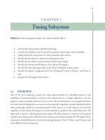
5.2.3 Duty Cycle
In many applications, periodic pulses are used as control signals. A good example is the use of a
periodic pulse to control a servo motor. To control the direction and sometimes the speed of a
motor, a periodic pulse signal with a changing duty cycle over time is used. The periodic pulse
signal shown in Figure 5.1(a) is on for 50% of the signal period and off for the rest of the period.
The pulse shown in Figure 5.1(b) is on for only 25% of the same period as the signal in Figure
5.1(a) and off for 75% of the period. The duty cycle is defined as the percentage of one period a
signal is on. Therefore, we call the signal in Figure 5.1(a) the periodic pulse signal with a 50% duty
cycle and the corresponding signal in Figure 5.1(b) the periodic pulse signal with a 25% duty cycle.
5.3 TIMING SYSTEM OVERVIEW
The heart of the timing system is the crystal time base. The crystal’s frequency of a microcontroller
is used to generate a baseline clock signal. For a timer system, the system clock is used to update
the contents of a special register called a free-running counter. The job of a free-running counter is
to count (increment) each time it sees a rising edge (or a falling edge) of a clock signal. Thus, if a
clock is running at the rate of 2 MHz, the free-running counter will count each
0.5 µ
s. All other
TIMING SUBSYSTEM 77
100 %
50 %
(a)
25 %
(b)
100 %
FIGURE 5.1: Two signals with the same period but different duty cycles: (a) periodic signal with a
50% duty cycle and (b) periodic signal with a 25% duty cycle.
timer-related units reference the contents of the free-running counter to perform I/O time-related
activities: measurement of periods, capture of timing events, and generation of time-related signals.
For input time-related activities, all microcontrollers typically have timer hardware com-
ponents that detect signal logic changes on one or more input pins. Such components rely on a
free-running counter to capture external event times. We can use such ability to measure the period
of an incoming signal, the width of a pulse, and the time of a signal logic change.
For output timer functions, a microcontroller uses a comparator, a free-running counter,
logic switches, and special-purpose registers to generate time-related signals on one or more output
pins. A comparator checks the value of the free-running counter for a match with the contents
of another special-purpose register where a programmer stores a specified time in terms of the
free-running counter value. The checking process is executed at each clock cycle, and when a match
occurs, the corresponding hardware system induces a programmed logic change on a programmed
78 ATMEL AVR MICROCONTROLLER PRIMER: PROGRAMMING AND INTERFACING
Free-Running
Counter
Special Storage
Register
Programmed
Event
- Toggle
- Logic high
- Logic low
Physical
Output
Pin
Timer Output
Flag
Timer Output
Interrupt
System
Comparator
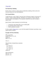
FIGURE 5.2: A diagram of a timer output system.
output port pin [5]. Using such capability, one can generate a simple logic change at a designated
time incident, a pulse with a desired time width, or a PWM signal to control servo or DC motors.
You can also use the timer input system to measure the pulse width of an aperiodic signal.
For example, suppose that the times for the rising edge and the falling edge of an incoming signal
are 1.5 and 1.6 s, respectively. We can use these values to easily compute the pulse width of 0.1 s.
The second overall goal of the timer system is to generate signals to control external devices.
Again, an event simply means a change of logic states on an output pin of a microcontroller
at a specified time. Now consider Figure 5.2. Suppose an external device connected to the
microcontroller requires a pulse signal to turn itself on. Suppose the particular pulse the external
device needs is 2-ms wide. In such situations, we can use the free-running counter value to
synchronize the time of desired logic state changes. Naturally, extending the same capability, we
can also generate a periodic pulse with a fixed duty cycle or a varying duty cycle.
Fromtheexampleswediscussedabove,youmay have wondered how a microcontroller
can be used to compute absolute times from the relative free-running counter values, say 1.5 and
TIMING SUBSYSTEM 79
1.6 s. The simple answer is that we cannot do so directly. A programmer must use the relative
system clock values and derive the absolute time values. Suppose your microcontroller is clocked
by a 2-MHz signal, and the system clock uses a 16-bit free-running counter. For such a system,
each clock period represents 0.5
µ
S, and it takes approximately 32.78 ms to count from 0 to 2
16
(65,536). The timer input system then uses the clock values to compute frequencies, periods, and
pulse widths. For example, suppose you want to measure a pulse width of an incoming aperiodic
signal. If the rising edge and the falling edge occurred at count values $0010 and $0114, can you
find the pulse width when the free-running counter is counting at 2 MHz? Recall that the $ symbol
represents that the following value is in a hexadecimal form. Let us first convert the two values into
their corresponding decimal values, 276 and 16. The pulse width of the signal in the number of
counter value is 260. Because we already know how long it takes for the system to count 1, we can
readily compute the pulse width as 260
×
0.5
µ
s
=
130
µ
s.
Our calculations do not take into account time increments lasting longer than the rollover
time of the counter. When a counter rolls over from its maximum value back to 0, a flag is set to
notify the processor of this event. The rollover events may be counted to correctly determine the
overall elapsed time of an event.
5.4 APPLICATIONS
In this section, we consider some important uses of the timer system of a microcontroller to (1)
measure an input signal timing event, termed input capture, (2) count the number of external signal
occurrences, (3) generate timed signals---termed output compare,and,finally,(4)generatePWM
signals. We first start with a case of measuring the time duration of an incoming signal.
5.4.1 Input Capture---Measuring External Timing Event
In many applications, we are interested in measuring the elapsed time or the frequency of an
external event using a microcontroller. Using the hardware and functional units discussed in the
previous sections, we now present a procedure to accomplish the task of computing the frequency of
an incoming periodic signal. Figure 5.3 shows an incoming periodic signal to our microcontroller.
The first necessary step for the current task is to turn on the timer system. To reduce power
consumption, a microcontroller usually does not turn on all of its functional systems after reset until
they are needed. In addition to a separate timer module, many microcontroller manufacturers allow
a programmer to choose the rate of a separate timer clock that governs the overall functions of a
timer module.
Once the timer is turned on and the clock rate is selected, a programmer must configure the
physical port to which the incoming signal arrives. This step is done using a special input timer
port configuration register. The next step is to program the input event to capture. In our current
80 ATMEL AVR MICROCONTROLLER PRIMER: PROGRAMMING AND INTERFACING
Timer Input Port
Timer Output Port
External
Device
Microcontroller
FIGURE 5.3: Use of the timer I/O systems of a microcontroller. The signal on top is fed into a timer
input port. The captured signal is subsequently used to compute the input signal frequency. The signal
on the bottom is generated using the timer output system. The signal is used to control an external
device.
example, we should capture two consecutive rising edges or falling edges of the incoming signal.
Again, the programming portion is done by storing an appropriate setup value to a special register.
Now that the input timer system is configured appropriately, you now have two options to
accomplish the task. The first one is the use of a polling technique; the microcontroller continuously
polls a flag, which holds a logic high signal when a programmed event occurs on the physical pin.
Once the microcontroller detects the flag, it needs to clear the flag and record the time when the
flag was set using another special register that captures the time of the associated free-running
counter value. The program needs to continue to wait for the next flag, which indicates the end of
one period of the incoming signal. A programmer then needs to record the newly acquired captured
time represented in the form of a free-running counter value again. The period of the signal can
now be computed by computing the time difference between the two captured event times, and
based on the clock speed of the microcontroller, the programmer can compute the actual time
changes and consequently the frequency of the signal.
In many cases, a microcontroller cannot afford the time to poll for one event. Such
situation introduces the second method: interrupt systems. Most microcontroller manufacturers
have developed built-in interrupt systems with their timer input modules. Instead of continuously
polling for a flag, a microcontroller performs other tasks and relies on its interrupt system to detect
the programmed event. The task of computing the period and the frequency is the same as the
first method, except that the microcontroller will not be tied down constantly checking the flag,
increasing the efficient use of the microcontroller resources. To use interrupt systems, of course,
we must pay the price by appropriately configuring the interrupt systems to be triggered when a
TIMING SUBSYSTEM 81
desired event is detected. Typically, additional registers must be configured, and a special program
called an ISR must be written.
Suppose that for an input capture scenario, the two captured times for the two rising edges are
$1000 and $5000, respectively. Note that these values are not absolute times but the representations
of times reflected as the values of the free-running counter. The period of the signal is $4000, or
16384 in a decimal form. If we assume that the timer clock runs at 10 MHz, the period of the
signal is 1.6384 ms, and the corresponding frequency of the signal is approximately 610.35 Hz.
5.4.2 Counting Events
The same capability of measuring the period of a signal can also be used to simply count external
events. Suppose we want to count the number of logic state changes of an incoming signal for a
given period. Again, we can use the polling technique or the interrupt technique to accomplish the
task. For both techniques, the initial steps of turning on a timer and configuring a physical input
port pin are the same. In this application, however, the programmed event should be any logic state
changes instead of looking for a rising or a falling edge as we have done in the previous section. If
the polling technique is used, at each event detection, the corresponding flag must be cleared and a
counter must be updated. If the interrupt technique is used, one must write an ISR within which
the flag is cleared and a counter is updated.
5.4.3 Output Compare---Generating Timing Signals to
Interface External Devices
In the previous two sections, we considered two applications of capturing external incoming signals.
In this subsection and the next one, we consider how a microcontroller can generate time critical
signals for external devices. Suppose in this application, we want to send a signal shown in Figure
5.3 to turn on an external device. The timing signal is arbitrary, but the application will show that a
timer output system can generate any desired time-related signals permitted under the timer clock
speed limit of the microcontroller.
Similar to the use of the timer input system, one must first turn on the timer system and
configure a physical pin as a timer output pin using special registers. In addition, one also needs to
program the desired external event using another special register associated with the timer output
system. To generate the signal shown in Figure 5.3, one must compute the time required between
the rising and the falling edges. Suppose that the external device requires a pulse that is 2 ms
wide to be activated. To generate the desired pulse, one must first program the logic state for the
particular pin to be low and set the time value using a special register with respect to the contents of
the free-running counter. As was mentioned in Section 5.2, at each clock cycle, the special register
contents are compared with the contents of the free-running counter, and when a match occurs, the
82 ATMEL AVR MICROCONTROLLER PRIMER: PROGRAMMING AND INTERFACING
programmed logic state appears on the designated hardware pin. Once the rising edge is generated,
the program then must reconfigure the event to be a falling edge (logic state low) and change the
contents of the special register to be compared with the free-running counter. For the particular
example in Figure 5.3, let us assume that the main clock runs at 2 MHz, the free-running counter is
a 16-bit counter, and the name of the special register (16-bit register) where we can put appropriate
values is output timer register. To generate the desired pulse, we can put $0000 first to the output
timer register, and after the rising edge has been generated, we need to change the program event
to a falling edge and put $0FA0 or 4000 in decimal to the output timer register. As was the case
with the input timer system module, we can use output timer system interrupts to generate the
desired signals as well.
5.4.4 Industrial Implementation Case Study (PWM)
In this section, we discuss a well-known method to control the speed of a DC motor using a PWM
signal. The underlying concept is as follows. If we turn on a DC motor and provide the required
voltage, the motor will run at its maximum speed. Suppose we turn the motor on and off rapidly
by applying a periodic signal. The motor at some point cannot react fast enough to the changes of
the voltage values and will run at the speed proportional to the average time the motor was turned
on. By changing the duty cycle, we can control the speed of a DC motor as we desire. Suppose
again we want to generate a speed profile shown in Figure 5.4. As shown in the figure, we want to
accelerate the speed, maintain the speed, and decelerate the speed for a fixed amount of time.
The first task necessary is again to turn on the timer system, configure a physical port, and
program the event to be a rising edge. As a part of the initialization process, we need to put $0000 to
the output timer register we discussed in the previous subsection. Once the rising edge is generated,
the program then needs to modify the event to a falling edge and change the contents of the output
timer register to a value proportional to a desired duty cycle. For example, if we want to start off
with 25% duty cycle, we need to input $4000 to the register, provided that we are using a 16-bit
free-running counter. Once the falling edge is generated, we now need to go back and change the
event to be a rising edge and the contents of the output timer counter value back to $0000. If we
want to continue to generate a 25% duty cycle signal, then we must repeat the process indefinitely.
Note that we are using the time for a free-running counter to count from $0000 to $FFFF as one
period.
Now suppose we want to increase the duty cycle to 50% over 1 s and that the clock is running
at 2 MHz. This means that the free-running counter counts from $0000 to $FFFF every 32.768
ms, and the free-running counter will count from $0000 to $FFFF approximately 30.51 times over
the period of 1 s. That is, we need to increase the pulse width from $4000 to $8000 in approximately
30 turns, or approximately 546 clock counts every turn.
TIMING SUBSYSTEM 83
Pulse Width Modulated Signal
Time
Motor Velocity
Acceleration
Period
Constant Speed
Period
Deceleration
Period
DC Motor
Speed Profile
GND
FIGURE 5.4: The figure shows the speed profile of a DC motor over time when a pulse-width-
modulated signal is applied to the motor.
5.5 OVERVIEW OF THE ATMEL TIMERS
The Atmel ATmega16 is equipped with a flexible and powerful three-channel timing system. The
timer channels are designated Timer 0, Timer 1, and Timer 2. In this section, we review the
operation of the timing system in detail. We begin with an overview of the timing system features,
followed by a detailed discussion of timer channel 0. Space does not permit a complete discussion
of the other two timing channels; we review their complement of registers and highlight their
features not contained in our discussion of timer channel 0. The information provided on timer
channel 0 is readily adapted to the other two channels.
The features of the timing system are summarized in Figure 5.5.Timer0andTimer2are
8-bit timers, whereas Timer 1 is a 16-bit timer. Each timing channel is equipped with a prescaler.
The prescaler is used to subdivide the main microcontroller clock source (designated f
clk I/O
in
upcoming diagrams) down to the clock source for the timing system (clk
Tn
).
84 ATMEL AVR MICROCONTROLLER PRIMER: PROGRAMMING AND INTERFACING
Timer 1
- 16-bit timer/counter
- 10-bit clock prescaler
- Functions:
– Pulse width modulation
– Frequency generation
– Event counter
– Output compare – 2 ch
– Input capture
- Modes of operation:
– Normal
– Clear timer on
compare match (CTC)
– Fast PWM
– Phase correct PWM
Timer 0
- 8-bit timer/counter
- 10-bit clock prescaler
- Functions:
– Pulse width modulation
– Frequency generation
– Event counter
– Output compare
- Modes of operation:
– Normal
– Clear timer on
compare match (CTC)
– Fast PWM
– Phase correct PWM
Timer 2
- 8-bit timer/counter
- 10-bit clock prescaler
- Functions:
– Pulse width modulation
– Frequency generation
– Event counter
– Output compare
- Modes of operation:
– Normal
– Clear timer on
compare match (CTC)
– Fast PWM
– Phase correct PWM
FIGURE 5.5: Atmel timer system overview.
Each timing channel has the capability to generate PWM signals, generate a periodic signal
with a specific frequency, count events, and generate a precision signal using the output compare
channels. Additionally, Timer 1 is equipped with the Input Capture feature.
All of the timing channels may be configured to operate in one of four operational modes
designated : Normal (Mode 0), Clear Timer on Compare Match (CTC) (Mode 1), Fast PWM
(mode 2), and Phase Correct PWM (mode 3). We provide more information on these modes
shortly.
5.6 TIMER 0 SYSTEM
In this section, we discuss the features, overall architecture, modes of operation, registers, and
programming of Timer 0. This information may be readily adapted to Timer 1 and Timer 2.
A Timer 0 block diagram is shown in Figure 5.6. The clock source for Timer 0 is provided
via an external clock source at the T0 pin (PB0) of the microcontroller. Timer 0 may also be clocked
internally via the microcontroller’s main clock ( f
clk I/O
). This clock frequency may be too rapid for
many applications. Therefore, the timing system is equipped with a prescaler to subdivide the main
clock frequency down to timer system frequency (clk
Tn
). The clock source for Timer 0 is selected
using the CS0[2:0] bits contained in the Timer/Control Register (TCCR0). The TCCR0 register
TIMING SUBSYSTEM 85
Timer/Counter Control
Register (TCCR0)
Control Logic
Timer/Counter
Register (TCNT0)
8-bit comparator
Output Compare
Register (OCR0)
Waveform Generator
WGM0[1:0]
COM0[1:0]
OC0
= 0
= 0xFF
top
bottom
8
82
2
top
botto
m
FOC0
3
Timer Counter Interrupt
Flag Register (TIFR)
Timer/Counter Interrupt
Mask Register (TIMSK)
clk
Tn
TOV0
CS0[2:0]
prescaler
f
clk_I/O
T0
external clock source
to WGM0[1:0]
to COM0[1:0]
FIGURE 5.6: Timer 0 block diagram.
also contains the WGM0[1:0] and the COM0[1:0] bits, which are used to select the mode of
operation for Timer 0 as well as tailor waveform generation for a specific application.
The timer clock source (clk
Tn
) is fed to the 8-bit Timer/Counter Register (TCNT0). This
register is incremented (or decremented) on each clk
Tn
clock pulse. Timer 0 is also equipped with
an 8-bit comparator that constantly compares the counts of TCNT0 to the Output Compare
Register (OCR0). The compare signal from the 8-bit comparator is fed to the waveform generator.
The waveform generator has a number of inputs (top, bottom, WGM0[1:0], and COM0[1:0]) to
perform different operations with the timer system.
The BOTTOM signal for the waveform generation and the control logic, shown in Figure
5.6, is asserted when the timer counter TCNT0 reaches all 0’s (0x00). The MAX signal for
the control logic unit is asserted when the counter reaches all 1’s (0xFF). The TOP signal for
the waveform generation is asserted by either reaching the maximum count values of 0xFF on the
86 ATMEL AVR MICROCONTROLLER PRIMER: PROGRAMMING AND INTERFACING
TCNT0 register or reaching the value set in the OCR0. The setting for the TOP signal will be
determined by the timer’s mode of operation.
Timer 0 also uses certain bits within the Timer/Counter Interrupt Mask Register (TIMSK)
and the Timer/Counter Interrupt Flag Register (TIFR) to signal interrupt-related events. Timer 0
shares these registers with the other two timer channels.
5.6.1 Modes of Operation
Each of the timer channels may be set for a specific mode of operation: normal, CTC, fast PWM,
and Phase Correct PWM. The system designer chooses the correct mode for the application at
Normal Mode (0)
(WGM01: 0, WGM00:0)
Clear Timer on Compare Match (CTC) Mode (1)
(WGM01: 0, WGM00:1)
Fast PWM Mode (2)
(WGM01: 1, WGM00:0)
Phase Correct PWM Mode (3)
(WGM01: 1, WGM00:1)
TCNT0
TOP
BOTTOM
TOV0 TOV0 TOV0
TCNT0
OCR0
OCR0
OCR0
OC0
OC0 OC0 OC0
OC0
f
OC0
= (f
clk_I/O
)/ (2 x N x (1 + OCR0))
OC0
inter
flag
TCNT0
TOP
BOTTOM
TOV0 TOV0 TOV0
OCR0
OCR0
OCR0
OC0
OC0 OC0
OC0
f
OC0PWM
= f
clk_I/O
/ (N x 256)
f
OC0PWM
= f
clk_I/O
/ (N x 510)
TCNT0
TOP
BOTTOM
TOV0 TOV0 TOV0
OCR0
OCR0
OC0 OC0 OC0
OC0
FIGURE 5.7: Timer 0 modes of operation.