Shop manual máy khoan hầm Boomer H282 - P3
Bạn đang xem bản rút gọn của tài liệu. Xem và tải ngay bản đầy đủ của tài liệu tại đây (2.55 MB, 90 trang )
PM No. 9852 1456 01b
2004-12
Atlas Copco
Boomer 281/282 with DC15 carrier
Operator’s instructions
Atlas Copco Rock Drills AB
SE-70191 Örebro, Sweden
SAFETY INSTRUCTIONS
Before starting, read all instructions carefully.
Special attention must be paid
to information alongside
this symbol.
Only use genuine Atlas Copco parts.
1250 0071 04
© Copyright 2004, Atlas Copco Rock Drills AB, Sweden
Any unauthorized use or copying of the contents or any part thereof is prohibited.
This applies in particular to trademarks, model denominations, part numbers and drawings.
Safety
3
Safety
Reference................................................................................................................. 5
Safety
4
Safety
5
Reference
Note
Always read the information under Safety before starting to use the rig or starting
maintenance work.
1250 0099 89
Safety
6
Operator’s instructions
7
Operator’s instructions
1. Technical data......................................................................................................... 11
Boomer/Rocket Boomer 280 with DC15, DC16 carrier ....................................... 11
Data plate............................................................................................................... 11
Data plate contents............................................................................................ 11
Location of data plate ....................................................................................... 12
2. Component locations.............................................................................................. 13
Main rig components............................................................................................. 13
3. Application............................................................................................................. 14
General .................................................................................................................. 14
4. Daily inspection ..................................................................................................... 15
General .................................................................................................................. 15
Checklist................................................................................................................ 15
Daily maintenance................................................................................................. 15
Freeze prevention measures .................................................................................. 16
5. Controls .................................................................................................................. 17
Locations ............................................................................................................... 17
Description of operation ........................................................................................ 18
Control panel .................................................................................................... 18
Control panel functions..................................................................................... 19
Drill panel ......................................................................................................... 22
Drill panel functions ......................................................................................... 22
Positioning panel .............................................................................................. 23
Positioning panel functions............................................................................... 24
Lever for protective roof, jacks and reeling units............................................. 24
6. Electrical system .................................................................................................... 26
Electric cubicle ...................................................................................................... 26
Resetting emergency stop...................................................................................... 27
7. Repositioning ......................................................................................................... 29
Environment .......................................................................................................... 29
Before starting the diesel engine ........................................................................... 29
Starting the diesel engine....................................................................................... 32
Before tramming.................................................................................................... 32
Checking the brakes .............................................................................................. 33
Checking the parking brake .............................................................................. 33
Checking service brakes ................................................................................... 33
Checking the interlock circuit........................................................................... 33
Repositioning......................................................................................................... 34
Safety ................................................................................................................ 34
Parking................................................................................................................... 35
Operator’s instructions
8
Operating the boom, jacks, protective roof and reeling units................................ 36
Control levers.................................................................................................... 36
Boom................................................................................................................. 37
Jacks.................................................................................................................. 37
Protective roof................................................................................................... 37
Cable reeling unit (option)................................................................................ 38
Unwinding the cable .................................................................................... 38
Reeling in the cable...................................................................................... 38
Water-hose reeling unit, option......................................................................... 39
Withdrawing the hose................................................................................... 39
Reeling in the hose ....................................................................................... 39
8. Positioning.............................................................................................................. 40
Positioning equipment ........................................................................................... 40
Positioning panel ................................................................................................... 41
Operating ............................................................................................................... 42
Safety ................................................................................................................ 42
Diesel operation ................................................................................................ 42
Raising and slewing the boom .......................................................................... 42
Slewing and inclining the feeder ...................................................................... 43
Feed lookout cylinder and boom telescope....................................................... 44
Rotation and feed extension.............................................................................. 45
Transport position ............................................................................................. 46
Bench drilling ................................................................................................... 47
Cross-cut drilling .............................................................................................. 47
Roof drilling...................................................................................................... 48
9. Drilling ................................................................................................................... 49
Environment .......................................................................................................... 49
Before drilling........................................................................................................ 49
Connect to power supply .................................................................................. 49
Battery .......................................................................................................... 49
Mains power................................................................................................. 49
Connect to water supply ................................................................................... 50
Connect the air supply ...................................................................................... 50
Checks............................................................................................................... 51
Setting up the rig............................................................................................... 51
Drilling................................................................................................................... 52
Drilling levers ................................................................................................... 52
Collaring and full drilling ................................................................................. 52
Cease drilling .................................................................................................... 53
Air blowing of drilled hole, option ................................................................... 53
Changing drill bit .............................................................................................. 54
Safety............................................................................................................ 54
Changing drill bit against rock face ............................................................. 54
Changing drill bit in bottom of hole............................................................. 55
Check when drilling.......................................................................................... 56
Safety............................................................................................................ 56
Operator’s instructions
9
Rock drill...................................................................................................... 56
System.......................................................................................................... 56
Hoses and couplings..................................................................................... 57
Settings ............................................................................................................. 57
Setting feed pressure .................................................................................... 57
Feed pressure for collaring........................................................................... 58
Feed pressure for full drilling....................................................................... 58
Feed pressure for full drilling of large holes, option.................................... 58
Introduction.................................................................................................. 59
Max. feed pressure (upper and lower cylinder) ........................................... 60
Pressure difference between upper and lower cylinder ............................... 60
Feed pressure for collaring and full drilling................................................. 61
Feed pressure, reverse.................................................................................. 61
Description................................................................................................... 62
RPCF feed control........................................................................................ 62
Feed (rock drill) return movement............................................................... 63
Setting the anti-jamming protection............................................................. 63
Setting the feed return movement ................................................................ 63
Setting RPCF during drilling ....................................................................... 64
After drilling.......................................................................................................... 65
Safety ................................................................................................................ 65
Freeze prevention measures.............................................................................. 65
10. Extension drilling, option..................................................................................... 66
Equipment for extension drilling........................................................................... 66
Operator panel ....................................................................................................... 67
Operating ............................................................................................................... 68
Safety ................................................................................................................ 68
Manual rod adding............................................................................................ 68
Preparation ................................................................................................... 68
Drilling and extension.................................................................................. 69
Removing drilling rods ................................................................................ 70
11. Directional control................................................................................................ 71
FAM....................................................................................................................... 71
Control panel ......................................................................................................... 71
Operating ............................................................................................................... 73
Start................................................................................................................... 73
Menus ............................................................................................................... 73
Main menu ................................................................................................... 74
Menu tree, branch 1 ..................................................................................... 74
Menu tree, branch 2 ..................................................................................... 75
Menu tree, branch 3 ..................................................................................... 76
Menu tree, branch 4 ..................................................................................... 77
Menu tree, branch 5 ..................................................................................... 78
Menu tree, branch 6 ..................................................................................... 79
Angle indication .................................................................................................... 80
Working menu drift drilling.............................................................................. 80
Operator’s instructions
10
Settings.............................................................................................................. 81
Length of full-depth drilled hole .................................................................. 81
Reference direction ...................................................................................... 81
Working menu ....................................................................................................... 82
Fault indication ...................................................................................................... 83
12. Air conditioning, option ....................................................................................... 84
General................................................................................................................... 84
Control panel ......................................................................................................... 84
Tip.......................................................................................................................... 85
In high ambient temperature ............................................................................. 85
Fogging in the cab............................................................................................. 85
13. Shift control, option.............................................................................................. 86
APC 50 (Automatic Powershift Control) .............................................................. 86
Description of operation ................................................................................... 86
Control panel..................................................................................................... 87
Display of current gear and direction of travel ............................................ 88
Display of turbine shaft speed...................................................................... 89
Display of tramming speed .......................................................................... 90
Display of fault codes................................................................................... 90
Operator’s instructions
1. Technical data
11
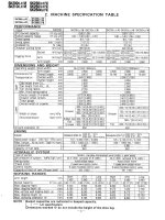
1. Technical data
Boomer/Rocket Boomer 280 with DC15, DC16
carrier
Note
A brief summary of data follows. For more detailed information, see the maintenance
instructions. All information applies to a standard-equipped rig.
Length, rig in transport position 9.9-11.7 m
Width 1.95 m
Height, rig with protective roof 2.3-3.0 m
Weight 17-20 tonnes
Installed diesel engine power 55 kW
Installed electric power capacity See data plate
Voltage See data plate
Frequency See data plate
Max. lateral inclination 0º
Max. longitudinal inclination. 14º
Stability Complies with CEN
Ambient temperature 0 to +40ºC
Noise level at operator's station (ISO/DIS 11201) 124 dB(A) re2 µΠα
Radiated acoustic power (ISO/DIS 11201) 124 dB(A) re1 pW
Vibration level, floor (ISO 2631/1)
0.12 m/s
2
Data plate
Data plate contents
The rig carries a data plate which contains the following data:
• Product name
• Product type
• Serial number
• Installed diesel engine power
• Installed electric power capacity
• Rated voltage
• Rated frequency
• Gross weight
Operator’s instructions
1. Technical data
12
The data plate also indicates whether the rig is CE certified.
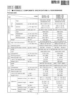
Location of data plate
Figure: Location of data plate
Rock Drills AB
Atlas Copco
STOCKHOLM - SWEDEN
Name
Type
Serial No.
Installed diesel power
Installed electric power
Rated voltage
Rated frequency
Gross weight
Made in Sweden 199
kW
V
Hz
kg
kW
9106 1071 90
1250 0072 81
Operator’s instructions
2. Component locations
13
2. Component locations
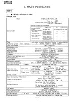
Main rig components
Figure: Boomer/Rocket Boomer with DC15 or DC16 carrier
1 Rock drill
2 Feeder
3 Boom
4 Front jacks
5
Rear jacks
6 Cable reeling unit
7 Water-hose reeling unit
8 Protective roof
1
2
3
4
5
6
7
1250 0070 75
8
Operator’s instructions
3. Application
14
3. Application
General
The drilling equipment is designed exclusively for drilling holes in tunnels and
mines. All other uses are considered to be inappropriate.
Examples of inappropriate use:
• Lifting and transporting loads and people
• Supporting objects
• Scaling rock
The manufacturer is not liable for damage caused by inappropriate use.
• It is essential the operator has read and comprehends the operator, maintenance
and repair manuals as well as the maintenance schedules.
• The drilling equipment must only be used, maintained and repaired by personnel
well conversant with the equipment and the dangers involved.
• It is essential that personnel observe general and local safety, health and traffic
regulations.
• The manufacturer is not liable to damage caused by any arbitrary changes made to
the drilling equipment.
Operator’s instructions
4. Daily inspection
15
4. Daily inspection
General
Note
To ensure optimal utilisation of the rig and its equipment, it is of utmost importance
that daily maintenance is carried out in accordance with our recommendations.
The objective for the daily inspection of the rig is to:
• detect faults at an early stage
• facilitate servicing
• allow scheduled maintenance and planned reconditioning work to be performed
• prevent costly secondary damage
• prevent breakdowns
• prevent personal injury
Note
Do not operate the rig or the rig equipment until all faults have been rectified.
Checklist
Note
As soon as a fault is detected, note it and report to maintenance personnel.
• Always begin by making an inspection round.
• Check safety devices
• Check hoses and cables
• Check oil levels
• Check the lubrication points.
• Keep your eyes open for possible leakage and wear.
• Pay attention to any faults in the function of the controls.
Daily maintenance
• Rinse off the rig with water, especially the feeder and other parts that have been
exposed to drill cuttings or rock debris
• See maintenance schedule for each component.
Operator’s instructions
4. Daily inspection
16
Freeze prevention measures
• Draining the water system, see maintenance instructions, Water system: Freeze
prevention measures.
• Draining the air tank, (option), see maintenance instructions, Air system: Freeze
prevention measures.
• Draining the scrubber (option), see maintenance instructions, Exhaust filtering:
Scrubber; Freeze prevention measures.
• Draining of Swellex pump (option), see maintenance instructions, for Swellex
pump: Freeze prevention measures.
Operator’s instructions
5. Controls
17
5. Controls
Locations
Figure: Location of controls, DC15 carrier
A Operator's area with control panel
B Levers for operating protective roof
C Levers for operating jacks
D Levers for diesel positioning
E Drilling and positioning panel
A
B
C
D
E
1250 0141 91
Operator’s instructions
5. Controls
18
Figure: Overview, operator's area
A Control panel
B Brake pedal
C Accelerator
Description of operation
Control panel
Figure: Control panel
A
B
C
1250 0013 88
N
1
2
2
1
P
H11
H12
H13
H14
H15
H16
H17
H18
30
40
60
50
20
10
P1
0
4/4
P2
H20
T10
T5
T6
T8
T2
P
T4
12500065 09
Operator’s instructions
5. Controls
19
Control panel functions
Table: Control panel functions
Designation Function Description
H11 Indicator lamp for parking brake The lamp shines if the parking brake is applied.
H12 Indicator lamp for transmission The lamp shines if the transmission fluid pressure
is too low or if its temperature is too high. The
parking brake is also applied. Contact maintenance
personnel.
H13 Indicator lamp for brake
pressure
Indicates that the hydraulic oil pressure in the brake
circuit is too low. If the lamp shines, the rig should
not be operated. Contact maintenance personnel.
H14 Indicator lamp for hydraulic oil
level
This lamp shines if the level of fluid in the hydraulic
oil tank is too low. The hydraulic oil must be topped
up immediately.
H15 Indicator lamp for fan belt This lamp shines if the fan belt breaks. The belt
must be replaced immediately. Contact
maintenance personnel.
H16 Indicator lamp for diesel engine
lubricating oil pressure
This lamp shines if the pressure is too low. If this
occurs, the engine must be switched off
immediately and the cause rectified by
maintenance personnel.
H17 Indicator lamps for engine
temperature
This lamp comes on if the temperature is too high.
The engine must be switched off immediately and
maintenance personnel contacted if the lamp
comes on during operation.
H18 Indicator lamp for battery
charging
Under normal driving conditions, the lamp should
be out to indicate the batteries are charging. The
lamp is on when the ignition is on. Contact
maintenance personnel if the lamp comes on while
driving.
H20 Preheating indicator
1250 0116 14
1250 0116 15
1250 0116 33
1250 0116 17
1250 0116 18
1250 0116 19
1250 0116 20
1250 0116 21
1250 0116 22
Operator’s instructions
5. Controls
20
T2 Ignition switch
T3 Button for differential lock The differential lock is activated when the button is
depressed.
T4 Button for parking brake The brake is applied when the button is depressed
and released when the button is extended. The
parking brake must be applied for the diesel engine
to be started.
T5 Switch for roof-mounted lighting
T5 Switch for roof-mounted lighting
T6 Switch for lighting on carrier
T7 Switch for lighting on carrier
T8 Button for lamp test When the button is depressed, all indicator lamps
should light simultaneously. If an indicator lamp
does not work, this should be changed
immediately.
T10 Gear selector The gear selector must be in neutral (N) for the
diesel engine to be started.
T12 Horn button
Designation Function Description
1250 0116 23
1250 0116 24
1250 0116 25
1250 0116 26
1250 0116 34
1250 0116 35
1250 0116 27
1250 0116 28
1250 0116 29
1250 0116 30
Operator’s instructions
5. Controls
21
P1 Hour counter for diesel engine Shows the diesel engine's operating hours
P2 Tank meter Shows the level of fuel in the diesel tank
Designation Function Description
1250 0116 31
1250 0116 32
Operator’s instructions
5. Controls
22
Drill panel
Figure: Drill panel
Drill panel functions
Table: Drill panel functions
Designation Function
S106 Button for stopping hydraulic pump
S105 Button for starting hydraulic pump
Lr Rotation lever
Lh Percussion lever
Lf Feed lever
2
4
6
8
12
14
16
bar
10
0
20
30
40
bar
10
0
20
30
40
bar
10
0
20
30
40
bar
10
2
4
6
8
12
14
16
bar
10
0
20
30
40
bar
10
0
20
30
40
bar
10
0
20
30
40
bar
10
S106
S105
Lr
Lh
Lf
Vfl
Vfh
Gr
Gh
Gf
Gl
Blb
Law
Ga Gw
GrfGdp
V1a
V1b
Lrn
Lds
Ltf
Lrb
V6
1250 0141 90
Operator’s instructions
5. Controls
23
Positioning panel
Figure: Positioning panel
Vfl Valve for feed pressure, collaring
Vfh Valve for feed pressure, full drilling
Gr Rotation pressure gauge
Gh Percussion pressure gauge
Gf Feed pressure gauge
Gl Lubricating oil pressure gauge
Gdp Pressure gauge for damper pressure (DCS 18
only)
Ga Air pressure gauge
Grf Pressure gauge for blocked return oil filter in
hydraulic oil reservoir (DCS 18 only)
Gw Water pressure gauge
Blb Button for removing the drill bit (DCS 18 only)
Law Water flushing lever
Lrb Small hole - large hole selector lever
V6 Pressure control valve
V1a RPCF valve, standard
V1b RPCF valve for large hole, option
Ltf Feed lever for threading and unthreading rods
Lds Lever to open/close front drill-steel support BSH
110
Lrn Single-rod/extension drilling selector lever
Designation Function
1250 0130 77
Lfr
Lfl
Lbe
Lfe
Bap
Lb
c
Operator’s instructions
5. Controls
24
Positioning panel functions
Table: Positioning panel functions
Lever for protective roof, jacks and reeling units
Figure: Levers for diesel positioning
Table: Levers for diesel positioning
No. Function
Lfr Lever for feed rotation
Lfl Lever for feed lookout
Lbe Lever for boom telescope
Lfe Lever for feed extension
Bap Anti-parallel button
Lbc Lever for boom positioning
LEVER FUNCTION
P1 For rigs with only cable reeling unit switching
between
• Boom positioning
• Neutral
• Reeling
T2
T1
D5
D4
D3
D2
D1
P2
K
S
1250 0141 89
T2
T1
D5
D4
D3
D2
D1
P1
K
Operator’s instructions
5. Controls
25
P2 For rigs with cable and hose reeling units
switching between
• Boom positioning
•Neutral
• Reeling
K Operating the cable reeling unit
S Operating the hose reeling unit
T1 Protective roof up/down (one of two cylinders)
T2 Protective roof up/down (one of two cylinders)
D5 Jack, front left, up/down
D4 Jack, front left, in/out
D3 Jacks, rear, up/down
D2 Jack, front right, in/out
D1 Jack, front right, up/down
LEVER FUNCTION