DOOSAN AC SERVO MOTORDRIVE VISION DVSC TM Series
Bạn đang xem bản rút gọn của tài liệu. Xem và tải ngay bản đầy đủ của tài liệu tại đây (2.19 MB, 127 trang )
NO. 300421-00003
DOOSAN AC SERVO MOTOR/DRIVE
VISION
DVSC - TM Series
MODEL: 0.8KW/1.5KW/1.7KW/2.0KW/2.3KW/3.0KW/4.0KW
Operation Manual
REV. B
DOOSAN INFRACORE
▶ Version History
Changed Contents
Ver.
Ver. B
-------------- Servo drive for Turret/Magazine --------------
Modification of Servo motor in 1.1 Formal type designation (Page 1)
Modification of 1.6 Outside circuit connection diagram (Page 15)
Modification of 1.7 Layout of connector terminal CN1, CN2 (Page 18)
Modification of contents in 2.1 Automatic operation (Page 22)
Add 2.7 Switch of display mode, parameter and position compensation value setting
method at the time an alarm occurs (Page 31)
Add 2.8 S-shaped acceleration/deceleration setting method (Page 33)
Add 2.9 Backlash compensation setting method (Page 34)
Add 2.10 Teaching function setting method (Page 36)
Add 2.11 Position signal output selection function (Page 39)
Modification of 3.2.2 Display Flowchart (Page 45)
Add 3.4.6 Teaching function setting (Page 52)
Add 3.4.7 Position signal output whole zone setting (Page 52)
Add 3.4.8 Angle setting by position signal section (Page 53)
Modification of 3.4.9 Drive itself JOG operation (Page 53)
Modification of 3.5.2 Drive operation at alarm occurrence (Page 58)
Modification of 3.6.2 User parameter list (Page 63)
Modification of parameter 0 contents in 3.6.3 Detailed explanation of user parameter
(Page 64)
Modification of parameter 5 contents in 3.6.3 Detailed explanation of user parameter
(Page 65)
Modification of parameter 31 contents in 3.6.3 Detailed explanation of user
parameter (Page 68)
Modification of parameter 48 contents in 3.6.3 Detailed explanation of user
parameter (Page 70)
Modification of parameter 50 contents in 3.6.3 Detailed explanation of user
parameter (Page 70)
Modification of parameter 56 contents in 3.6.3 Detailed explanation of user
parameter (Page 71)
---------------- Servo drive for ATC ----------------
Modification of 1.6 Outside circuit connection diagram (Page 78)
Modification of contents in 2.1 Automatic operation (Page 83)
Changed Contents
Ver.
Ver. B
---------------- Servo drive for ATC ----------------
Add 2.5 Switch of display mode, parameter and position compensation value setting
method at the time an alarm occurs (Page 90)
Add 2.6 S-shaped acceleration/deceleration setting method (Page 92)
Modification of 3.2.2 Display Flowchart (Page 95)
Modification of 3.4.6 Maker management items (Page 102)
Modification of 3.4.7 Drive itself JOG operation (Page 102)
Modification of 3.5.2 Drive operation at alarm occurrence (Page 106)
Modification of 3.6.2 User parameter list (Page 111)
Modification of parameter 0 contents in 3.6.3 Detailed explanation of user parameter
(Page 113)
- CONTENTS WARNING ........................................................................................................ i
COMMON SUBJECT ......................................................................................... 1
1. Specifications and Composition...................................................................... 1
1.1.
1.2.
1.3.
1.4.
1.5.
1.6.
1.7.
Formal type designation .................................................................................................... 1
Specifications for Servo Motor ............................................................................................ 2
Torque-Speed Characteristics of Servo Motor(2.0KW) ............................................................ 2
Specifications for Servo Drive............................................................................................. 3
Coupling of the Servo Motor / Drive..................................................................................... 4
Inner structure of Servo Drive ............................................................................................. 4
Rotation direction of the servo motor ................................................................................... 5
2. Dimensions of the servo motor / drive ............................................................. 6
2.1. Dimensions of the servo motor ........................................................................................... 6
2.2. Dimensions of the servo drive .......................................................................................... 10
Servo drive for Turret and Magazine ................................................................... 11
1. Installation and wiring .................................................................................. 11
1.1. Designations ................................................................................................................. 11
1.2. Environmental conditions ................................................................................................. 12
1.3. Installation method ......................................................................................................... 12
1.4. Wiring ........................................................................................................................... 14
1.5. Noise treatment.............................................................................................................. 14
1.6. Outside circuit connection diagram(example)...................................................................... 15
1.7. Layout of drive connector terminal .................................................................................... 18
1.8. Signals for connector CN1 and their meanings .................................................................... 19
1.9. Signals for connector CN2 and their meanings .................................................................... 20
1.10. Structure of drive I/O circuit ........................................................................................... 21
2. Operation .................................................................................................. 22
2.1. Automatic operation ........................................................................................................ 22
2.2. Jog operation and Usage of BRAKE Signal(Magazine Port move by the jog signal) ................... 23
2.3. Parameter and Machine Origin setting method after replacement of the servo drive .................. 24
2.4. Selective application of the position compensation value by external signal ............................. 28
2.5. Operation of servo drive in JOG mode by external signal ...................................................... 29
2.6. Machine Origin setting method by external signal ................................................................ 30
2.7. Switch of display mode, parameter and position compensation value setting ........................... 31
2.8. S-shaped acceleration/deceleration setting method ............................................................ 33
2.9. Backlash compensation setting method ............................................................................. 34
2.10. Teaching function setting method ................................................................................... 36
2.11. Position signal output selection function........................................................................... 39
3. Display/Setting part ..................................................................................... 43
3.1.
3.2.
3.3.
3.4.
3.5.
3.6.
Functions ...................................................................................................................... 43
Operating of the Display/Setting part and display flowchart ................................................... 44
State display .................................................................................................................. 46
Diagnosis display ........................................................................................................... 49
Alarm history display ....................................................................................................... 58
User Parameter setting and Detailed explanation ................................................................. 61
3.7. Position compensation value setting .................................................................................. 72
Servo drive for ATC ......................................................................................... 74
1. Installation and wiring .................................................................................. 74
1.1. Designations ................................................................................................................. 74
1.2. Environmental conditions ................................................................................................. 75
1.3. Installation method ......................................................................................................... 75
1.4. Wiring ........................................................................................................................... 77
1.5. Noise treatment.............................................................................................................. 77
1.6. Outside circuit connection diagram(example)...................................................................... 78
1.7. Layout of drive connector terminal .................................................................................... 79
1.8. Signals for connector CN1 and their meanings .................................................................... 80
1.9. Signals for connector CN2 and their meanings .................................................................... 81
1.10. Structure of drive I/O circuit ........................................................................................... 82
2. Operation .................................................................................................. 83
2.1.
2.2.
2.3.
2.4.
2.5.
2.6.
Automatic operation ........................................................................................................ 83
Parameter and Machine Origin setting method after replacement of the servo drive .................. 84
Operation of servo drive in JOG mode by external signal ...................................................... 88
Machine Origin setting method by external signal ................................................................ 89
Switch of display mode, parameter and position compensation value setting ........................... 90
S-shaped acceleration/deceleration setting method ............................................................ 92
3. Display/Setting part ..................................................................................... 93
3.1.
3.2.
3.3.
3.4.
3.5.
3.6.
Functions ...................................................................................................................... 93
Operating of the Display/Setting part and display flowchart ................................................... 94
State display .................................................................................................................. 96
Diagnosis display ........................................................................................................... 99
Alarm history display ..................................................................................................... 106
User Parameter setting and Detailed explanation ............................................................... 109
WARNING
I. Definition of Symbols for Warning
1)
DANGER
2)
!
DANGER
Warning : This symbol means that there is possible of danger such as
electric shock , if not handled properly.
Caution : This symbol means that there is possible of danger such as
receiving a slight or serious injuries or machine damages, if not
handled properly.
II. Warning
1) Do not use in areas near corrosive, inflammable or explosive gas.
2) Take appropriate measures of protection while the servo motor is in operation.
3) While installing and wiring, turn the power switch off, in order to prevent electric
shock.
4) Ground the PE terminal block of the front panel terminal block L1(R), L2(S), L3(T) to
one-point with the class 3 (below 100Ω) ground circuit, in order to prevent electric
shock or other malfunctions. For PE terminal block, use wire 40mm2 thicker than the
electric wire of the terminal L1, L2, L3.
5) Connect the PE terminal block of the servo motor to the PE terminal block U, V, W
of the servo drive in order to prevent electric shock. To connect the wire, use wire
40mm2 thicker than the power line of U, V, W.
6) Take precautions while mounting, dismantling, uninstalling and transferring the servo
motor.
7) Cover the terminal block while using the servo drive in order to prevent electric shock.
8) Use the reinforcement wire SELV for maintenance brake power switch, input and output
power switch and input and output signal in order to prevent electric shock.
9) Do not dismantle the servo drive within 5 minutes after shutting off the main power.
– Charged voltage may still remain inside the drive.
10) This product uses batteries. Take the following precautions while using the battery.
If used inappropriately, explosion or fire may occur. The contents of the battery are
harmful to the eye.
① Do not heat above 100℃ and do not open when there is fire.
② Do not take it apart. (The contents are harmful to the eye.)
i
③ Do not recharge it.
11) During emergency shutdown, stop the servo motor before shutting down the servo
drive (terminal L1, L2, L3).
III. Caution
1) To avoid burns, do not touch the heat protecting board or the regenerative resistor of
the servo motor and drive while the servo motor is in operation or right after turning off
the power switch. Take appropriate measures of protection.
2) Avoid the following to prevent damages to the servo motor and servo drive.
① Do not connect the power directly to the U, V, W terminal block of the servo motor.
The servo motor will be damaged.
② Avoid external impact such as hammering to the servo motor. The encoder inside
the servo motor will be damaged.
③ Do not connect the power to the U, V, W terminal block of the servo drive.
④ While doing the resisting pressure test or insulation voltage test, disconnect the
terminal of the servo drive terminal block or all the connectors and avoid the test
voltage from affecting the servo drive. Also avoid the test voltage from affecting
the encoder connector terminal of the servo motor.
⑤ Do not install the servo motor and the servo drive differently than it should.
⑥ Prevent water or oil from directly touching the servo motor. Use in areas free of
water or oil to prevent it from touching the main wire of the servo motor.
⑦ Do not use the servo motor and drive differently other than stated in this manual.
ii
DOOSAN TM SERVO OPERATION MANUAL
COMMON SUBJECT
1. Specifications and Composition
1.1. Formal type designation
◆ Servo Motor
RH 20 T A – 5 O O
TYPE
RH SERIES
RG SERIES
OIL SEAL
O : OIL SEAL
N : NON-OIL SEAL
OUTPUT
08
15
17
20
23
28
30
40
:
:
:
:
:
:
:
:
0.8KW
1.5KW
1.7KW
2.0KW
2.3KW
2.8KW
3.0KW
4.0KW
BRAKE
B : BRAKE
O : NON BRAKE
TAPER
ENCODER
T : 17BIT ABS
ROTATOR & ENCODER TYPE
A : SM-PMSM, Integrated Encoder
B : IPM-PMSM, Integrated Encoder
C : SM-PMSM, Separate Encoder
D : IPM-PMSM, Separate Encoder
E : Special
1
2
3
4
5
6
7
:
:
:
:
:
:
:
STRAIGHT KEY(OPEN TYPE)
TAPER KEY(PARALLEL)
STRAIGHT
TAPER
TAPER KEY(HALF-MOON)
STRAIGHT KEY(ENCLOSED)
GEAR
◆ Servo Drive
DVSC-TM-14 D-01
COMPACT
DRIVE SERIES
TYPE
TT : TURRET/MAG.
TA : ATC
TX : 2 AXIS
TM: TURRET/MAG./ATC
S/W VERSION
NO. : 0 ~ 9
H/W VERSION
NO. : A ~ Z
Rated Current Capacity
14 : 14A (Bellow 2.0KW Motor)
28 : 28A (Bellow 4.0KW Motor)
1
DOOSAN TM SERVO OPERATION MANUAL
1.2. Specifications for Servo Motor
Items
Specifications
kWatt
0.8
1.5
2.0
3.0
4.0
kgf∙cm
25.98
73.08
97.44
146.16
194.88
N∙m
2.55
7.16
9.54
14.32
19.11
Continuous
maximum
torque
kgf∙cm
77.95
219.24
292.32
438.48
584.64
N∙m
7.64
21.49
28.66
42.49
57.32
Rated speed
RPM
2,000
Maximum
speed
RPM
3,000
Power rate
kW/S
Rated output
Rated torque
SERVO
Rotor Inertia
MOTOR
×10
-4
2
kg·m
23.64
13.28
42.29
90.94
34.78
2.8
39.4
22
23.02
107
Insulation class
F Class
Detector
Multi-turn Absolute Encoder
(17bits/1 rotation, rotation count :16bits)
Protection, Cooling method
Totally closed, self cooled
Ambient temperature
0 ~ 40°C
Ambient humidity
20 ~ 80%
Mounting structure
Flange type
Insulation resistance
DC 500V 20 Mohm
Insulation voltage
AC 1,500V for one minute
Vibration class
V15
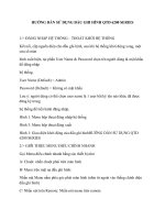
1.3. Torque-Speed Characteristics of Servo Motor(2.0KW)
※ Refer to Motor Specifications for details.
2
DOOSAN TM SERVO OPERATION MANUAL
1.4. Specifications for Servo Drive
Specifications
Applied motor capacity
0.8KW / 1.5KW 1.7KW/ 2.0KW / 2.3kW
2.8KW / 3.0KW / 4.0KW
Rated current
14A rms
28A rms
Maximum current
40A peak
80A peak
Rotation speed
RH : 2,000rpm / 3,000rpm (Rated / Maximum)
RG : 1,150rpm / 1,500rpm (Rated / Maximum)
Main input voltage
3 phase 200/220V +10% ~ -15%, 50/60Hz ±5%
Control period
62.5μsec
Braking type
Resistor discharge regenerative braking by built-in regenerative circuit
Control mode
Position/ speed/ torque control
Control circuit
3 phase Voltage PWM Inverter Driving (IPM)
Full Digital Vector Control (Position detection by Pulse Encoder)
Type
Absolute Encoder
Resolution
17bit (131,072)
Encoder Spec.
I/O Terminal block
Input electric power (R, S, T), Output electric power (U, V, W), Ground (E)
Protection Functions
Over voltage, under voltage, over current, over speed,
over load, encoder error and etc.
Other Functions
Parameter setting, Diagnosis, Alarm Display and State Display by
Display/Setting parts
Ambient temperature
0 ~ 50℃,
Ambient humidity
Below 90%RH (don't be covered with dew)
Preservation temperature
-20 ~ 85℃
Altitude
Below 1,000m
Vibrations
Below 0.5G
Mounting
Rack Mount
3
DOOSAN TM SERVO OPERATION MANUAL
1.5. Coupling of the Servo Motor / Drive
1.6. Inner structure of Servo Drive
AC/DC
IPM INVERTER
3PHASE
200/220V
AC
SEQUENCE/
POSITION
INPUT
SEQUENCE/
POSITION
OUTPUT
DSP
&
MEMORY
NC PLC
DISPLAY
&
SWITCH
4
A/D
Converter
ENCODER
Interface
DOOSAN TM SERVO OPERATION MANUAL
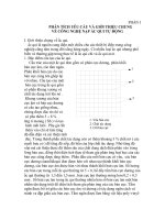
1.7. Rotation direction of the servo motor
▶
Caution: The encoder of the servo motor is made of glass.
Take precautions in order to avoid damages to the encoder shaft of the servo motor.
▶
Caution: Make sure the rotation direction is correct when the servo motor rotates.
◆ The correct rotation direction is shown in the following picture.
Forward direction (CCW)
5
DOOSAN TM SERVO OPERATION MANUAL
2. Dimensions of the servo motor / drive
2.1. Dimensions of the servo motor
■ 800W
6
DOOSAN TM SERVO OPERATION MANUAL
■ 1.5KW / 2.0kW
7
DOOSAN TM SERVO OPERATION MANUAL
■ 3.0kW
8
DOOSAN TM SERVO OPERATION MANUAL
■ 4.0kW
9
DOOSAN TM SERVO OPERATION MANUAL
2.2. Dimensions of the servo drive
■ 14A : for 0.8/1.5/1.7/2.0/2.3kW motors
■ 28A : for 2.8/3.0/4.0kW motors
10
DOOSAN TM SERVO OPERATION MANUAL
Servo drive for Turret and Magazine
1. Installation and wiring
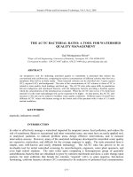
1.1. Designations
Designations of DOOSAN AC Servo Motor and Drive are as follows.
Please refer to this section for system installation and after service.
1)Encoder Connector 2)Power Connector 3)Name Plate 4)Shaft 5 )Flange 6 )Frame 7 )Encoder
MODE
SET
VISION C
AC SERVO DRIVER
BATT
PULL
Encoder signal
connector
CN3
PCN1
CN4
P/N : 300419-00035
3 phase input
power connector
R S
T
CN2
Control output signal
connector
Motor power
connector
Control input signal
connector
CN1
U V
W
PCN2
DVSC-TM-14D-01
11
DOOSAN TM SERVO OPERATION MANUAL
1.2. Environmental conditions
This product was designed for indoor usage.
Caution : If used in different circumstances and environment other than stated below, damages
may occur.
Please use under the following conditions.
SERVO MOTOR
SERVO DRIVE
Voltage
-
3 phase AC 200V ~ 220V
+10 ~ -15%, 50/60Hz
Ambient
Temperature
0 ~ +40℃
0 ~ +50℃
Storage
Temperature
-25 ~ +80℃
-25 ~ +65℃
Humidity
Below 80% RH
Below 90% RH
Environmental
Conditions
(1) Use in areas free of corrosive and explosive gas.
(2) Use in areas that are well ventilated.
(3) Nearby vibrations or tremors may be the cause of loose contact of the
connector, electronic connector device and relay.
Waterproof /
Oil proof
(1) The protection level of the servo motor is IP-54.
Please lay a cover in areas where there is massive water and oil.
(2) When installing the servo motor, the connector should be assembled as
downward direction.
Other
Please refer to chapter 2 while assembling and handling the wires.
1.3. Installation method
1.3.1. Assembling of the servo motor
▷
▷
▷
▷
▷
▷
12
Warning: While assembling the servo motor, avoid dropping it.
Caution: While mounting the servo motor horizontally, the connector should be assembled
facing downward.
The servo motor can be mounted horizontally or vertically.
To prevent vibrations and extend the life of coupling and bearing, the motor shaft and the loading
shaft should be precisely aligned. Use flexible coupling when connecting directly to the load.
① The outer part of the coupling should be measured at four equidistant points each 90˚ apart,
and the gap between the maximum and the minimum readings should not exceed 0.03㎜.
② The center point of the motor and the loading shaft should be precisely aligned.
Avoid excessive radial and thrust load to the motor shaft and also avoid impact that is more
than 10G when mounting the gear, coupling, pulley and etc. at the same time.
A minus load means continuous operation in the regenerative braking state, when the motor is
rotated by load. The regenerative braking capacity of the servo drive is short term rated
specification equivalent to stop time of the motor. Thus, it should not be used in minus load that
generates continuous regenerative braking.
ex) Servo system for descending objects(without counterweight)
DOOSAN TM SERVO OPERATION MANUAL
▷ The admissible load inertia into the motor shaft is within 5 times than the inertia of applied servo
motor. If it exceeds this, during deceleration it may cause regenerative malfunction.
The following steps should be taken if the load inertia exceeds more than 5 times the inertia of
the servo motor.
- Reduce the current limit.
– Decelerate slowly.(Slow Down)
- Lower the maximum speed in use.
1.3.2. Mounting of the servo drive
▷
Warning: To prevent electric shock, turn off the power while mounting or uninstalling.
▷ While installing the panel, the size of the panel, cooling and wiring should be considered in
order to maintain a difference of temperature below 5℃ between the panel temperature and the
surrounding temperature in accordance with heat value of the equipment and box size.
▷ If a heating element is placed nearby, the surrounding temperature of the servo drive should be
maintained below 55℃ at all cases despite temperature rise by convection and radiation. Use a
fan to ventilate sealed inner air, and proper ventilation should be used for convection of the air.
▷ If a vibrating element is placed nearby, the drive should be mounted on shock absorbing surface.
▷ If the servo drive be exposed to corrosive gas for a long time, may cause damages to connecting
devices such as relay and circuit breaker, thus it should be avoided.
▷ Environmental conditions such as high temperature, high humidity, excessive dust and metal
particles should be avoided.
◆ Mounting method
▷ There should be a space wider than 100㎜ below and above the servo drive.
▷ There should be a space wider than 30㎜ on both sides of the servo drive.
▷ Mount the servo drive vertically. Do not use if it is mounted horizontally.
13
DOOSAN TM SERVO OPERATION MANUAL
1.4. Wiring
▶ For signal lines and encoder lines, use twisted lines or multi-core shielded twisted-pair lines.
The length for command input lines should be maximum 3m, and the encoder line should be
maximum 10m or less.
Wiring must be done in shortest distance and the remaining length should be cut.
▶ The ground circuit should be a thick line. Usage of third-class grounding or above (ground
resistance 100Ω or less) is recommended. Also, make sure to ground at one-point grounding.
▶ The following precautions should be taken to avoid malfunction due to noise.
- The noise filter should be placed as near as possible.
- Mount a surge absorber to the coil of the relay, electromagnetic contacts, solenoids and etc.
- The power line (AC input, motor input line) and the signal line should be placed 30㎝ apart
or more. Do not put them into the same duct or tie them in a bundle.
- If the power source of the servo drive is used in common with an electric welder or electrical
discharge machine, or a high-frequency noise source is present, attach noise filter to the
power or the input circuits.
- Since the core wire of the signal line cable is as thin as only 0.2 ~ 0.3㎟, excessive force to the
line should be avoided to prevent damages.
1.5. Noise treatment
For wiring and grounding of the servo drive, the effect of switching noise which is generated by the
built-in IPM should be reduced as much as possible. Unexpected effect by outside noise should be
reduced as much as possible.
▶ Grounding method
The servo drive supplies power to the motor according to the switching of the IPM device.
Thus the Cf dv/dt current flows from the power component to the floating capacity of the motor.
To prevent the effect of the switching noise, the motor frame terminal should be connected to
the PE terminal of the servo drive terminal block and the PE terminal of the servo drive should be
directly grounded to standard ground panel.
▶ Noise filter
Noise filter is used in order to prevent noise from the power line. Please refer to the following
conditions while installing.
(a) Separate the input and output wiring and do not tie them together or put them into the same
duct.
(b) Do not put the ground wire into the same duct with the filter output line or other signal lines.
And do not tie them together.
(c) The ground wire should be wired singly to the ground panel.
(d) If the unit contains the filter, connect the filter and the equipment ground to the base of the
unit.
14
DOOSAN TM SERVO OPERATION MANUAL
1.6. Outside circuit connection diagram(example)
NC CONTROLLER
3 PHASE AC 220V
AC SERVO DRIVE
CN1
MCCB
COM1
A5
SEQUENCE INPUT
SPARE
DC
24V
STOP
JOGJOG+
SVON
SPARE
NOISE
FILTER
B6
A6
PCN1
B7
COM2
START
DC
24V
POSI6
POSI5
POSI4
A1
B8
B1
A8
A2
L1(R)
L3(T)
PE
AC SERVO MOTOR
A1
1.5KW
B2
A2
POSI0
OVR3
OVR2
OVR1
OVR0|POSI7
B3
A1
B1
B4
B2
A4
A2
BAT_L
ALM
RY1 SVRDY
AUX_OUT0|POSO7
AUX_OUT1
BRAKE+
DC
24V
BRAKE-
V
I
W
B
3.0KW
M
D
PE
B9
G
DC
24V
A9
B
RY2 H
B10
CN3
A10
CN2
DC
24V
F
E
A2,A3,A4
COM3
U
B5
A1,B1,B2
SEQUENCE OUTPUT
AUX OUTPUT
~
PCN2
A3
POSI1
MC1 MC1 MC1
L2(S)
B1
POSI3
POSI2
MC1 RY1
MC1
A7
B2
POSITION INPUT
OVERRIDE INPUT
POWER POWER
OFF
ON
B3
B4
A5
A5,B5
B6
B6
+5
H
GND
G
RX
K
RX/
L
BAT+
P
BAT-
R
PG
A6
J
B7
A7
A6
SHIELD
B8
B10
NOTE
A10
1. TWISTED PAIR SHIELDED CABLE
RY2
POSITION OUTPUT
DC
24V
COM4
VPF
POSO6
POSO5
POSO4
POSO3
POSO2
POSO1
POSO0
B1
B5
2. USE FOR BUILT-IN BRAKE TYPE MOTOR
3. CONNECTOR SPECIFICATION
MAKER : TYCO ELECTRONICS AMP
A4
LOCATION
LOCATION
RECEPTACLE
RECEPTACLE
HOUSING
HOUSING
RECEPTACLE
RECEPTACLE
CONTACT
CONTACT
CN1
1- 1318118-9
1318107-1
CN2
2- 1318118-9
1318107-1
B3
CN3
1- 1318118-6
1318107-1
A2
PCN1
1- 917807-2
316040- 6(14D)
316041- 6(28B)
PCN2
3- 917807-2
316040- 6(14D)
316041- 6(28B)
B4
A3
B2
A1
15
DOOSAN TM SERVO OPERATION MANUAL
NC CONTROLLER
3 PHASE AC 220V
AC SERVO DRIVE
CN1
MCCB
COM1
A5
SEQUENCE INPUT
SPARE
DC
24V
STOP
JOGJOG+
SVON
SPARE
NOISE
FILTER
B6
A6
B7
PCN1
COM2
START
DC
24V
POSI6
POSI5
POSI4
A1
B8
B1
A8
A2
L1(R)
L3(T)
PE
A1
AC SERVO MOTOR
B2
A2
POSI0
OVR3
OVR2
OVR1
OVR0|POSI7
A1
A2
BAT_L
ALM
RY1 SVRDY
AUX_OUT0|POSO7
AUX_OUT1
BRAKE+
DC
24V
BRAKE-
E
PE
C
M
D
B9
A
DC
24V
A9
B
RY2 F
B10
CN3
A10
CN2
DC
24V
G
B5
A2,A3,A4
COM3
B
V
B2
A4
U
W
B1
B4
A1,B1,B2
SEQUENCE OUTPUT
AUX OUTPUT
800W
PCN2
B3
A3
POSI1
MC1 MC1 MC1
L2(S)
B1
POSI3
POSI2
MC1 RY1
MC1
A7
B2
POSITION INPUT
OVERRIDE INPUT
POWER POWER
OFF
ON
B3
B4
A5
A5,B5
B6
B6
+5
B
GND
A
RX
D
RX/
E
BAT+
F
BAT-
G
A6
PG
C
B7
A7
A6
SHIELD
B8
B10
NOTE
A10
1. TWISTED PAIR SHIELDED CABLE
RY2
POSITION OUTPUT
DC
24V
COM4
VPF
POSO6
POSO5
POSO4
POSO3
POSO2
POSO1
POSO0
16
B1
B5
2. USE FOR BUILT-IN BRAKE TYPE MOTOR
3. CONNECTOR SPECIFICATION
MAKER : TYCO ELECTRONICS AMP
A4
LOCATION
LOCATION
RECEPTACLE
RECEPTACLE
HOUSING
HOUSING
RECEPTACLE
RECEPTACLE
CONTACT
CONTACT
CN1
1- 1318118-9
1318107-1
CN2
2- 1318118-9
1318107-1
CN3
1- 1318118-6
1318107-1
PCN1
1- 917807-2
316040- 6(14D)
316041- 6(28B)
PCN2
3- 917807-2
316040- 6(14D)
316041- 6(28B)
B4
A3
B3
A2
B2
A1
DOOSAN TM SERVO OPERATION MANUAL
NC CONTROLLER
3 PHASE AC 220V
AC SERVO DRIVE
CN1
MCCB
COM1
A5
SEQUENCE INPUT
SPARE
DC
24V
STOP
JOGJOG+
SVON
SPARE
NOISE
FILTER
B6
A6
B7
PCN1
COM2
START
DC
24V
POSI6
POSI5
POSI4
A1
B8
B1
A8
A2
L1(R)
L3(T)
PE
A1
AC SERVO MOTOR
B2
A2
POSI0
OVR3
OVR2
OVR1
OVR0|POSI7
A1
A2
BAT_L
ALM
RY1 SVRDY
AUX_OUT0|POSO7
AUX_OUT1
BRAKE+
DC
24V
BRAKE-
F
PE
G
M
H
B9
A
DC
24V
A9
B
RY2 B
B10
CN3
A10
CN2
DC
24V
E
B5
A2,A3,A4
COM3
D
V
B2
A4
U
W
B1
B4
A1,B1,B2
SEQUENCE OUTPUT
AUX OUTPUT
4.0KW
PCN2
B3
A3
POSI1
MC1 MC1 MC1
L2(S)
B1
POSI3
POSI2
MC1 RY1
MC1
A7
B2
POSITION INPUT
OVERRIDE INPUT
POWER POWER
OFF
ON
B3
B4
A5
A5,B5
B6
B6
+5
H
GND
G
RX
K
RX/
L
BAT+
P
BAT-
R
A6
PG
J
B7
A7
A6
SHIELD
B8
B10
NOTE
A10
1. TWISTED PAIR SHIELDED CABLE
RY2
POSITION OUTPUT
DC
24V
COM4
VPF
POSO6
POSO5
POSO4
POSO3
POSO2
POSO1
POSO0
B1
B5
2. USE FOR BUILT-IN BRAKE TYPE MOTOR
3. CONNECTOR SPECIFICATION
MAKER : TYCO ELECTRONICS AMP
A4
LOCATION
LOCATION
RECEPTACLE
RECEPTACLE
HOUSING
HOUSING
RECEPTACLE
RECEPTACLE
CONTACT
CONTACT
CN1
1- 1318118-9
1318107-1
CN2
2- 1318118-9
1318107-1
CN3
1- 1318118-6
1318107-1
PCN1
1- 917807-2
316040- 6(14D)
316041- 6(28B)
PCN2
3- 917807-2
316040- 6(14D)
316041- 6(28B)
B4
A3
B3
A2
B2
A1
17