Static analysis of reissner mindlin plates using ES+NS-MITC3 elements
Bạn đang xem bản rút gọn của tài liệu. Xem và tải ngay bản đầy đủ của tài liệu tại đây (5.24 MB, 13 trang )
Journal of Science and Technology in Civil Engineering NUCE 2019. 13 (3): 45–57
STATIC ANALYSIS OF REISSNER-MINDLIN PLATES USING
ES+NS-MITC3 ELEMENTS
Chau Dinh Thanha,∗, Ho Thi Conb , Le Phuong Binha
a
Faculty of Civil Engineering, HCMC University of Technology and Education,
1 Vo Van Ngan street, Thu Duc district, Ho Chi Minh city, Vietnam
b
Center for Vocational and Regular Education, Chau Phu district, An Giang province, Vietnam
Article history:
Received 09/08/2019, Revised 29/08/2019, Accepted 30/08/2019
Abstract
In this research, the smoothed finite element methods (S-FEM) based on the edge-based (ES) and node-based
(NS) approaches are combined to develop for the 3-node triangular plate element which uses the mixed interpolation of tensorial components (MITC3) technique to remove the shear-locking phenomenon. This approach
is based on the βFEM in which the parameter β is used to tune the contribution ratio of the edge-based and
node-based smoothed domains. The strain fields of the proposed ES+NS-MITC3 element are smoothed on a
part of the edge-based domains and the other on the node-based domains which are respectively defined by
elements sharing common edges and common nodes. The ES+NS-MITC3 element passes the patch test and is
employed to statically analyze some benchmark Reissner-Mindlin plates, including square and rhombus ones.
Numerical results show that, in both thin and thick plates the ES+NS-MITC3 element can give results better
than similar elements using the ES-FEM or NS-FEM only.
Keywords: Reissner-Mindlin plates; MITC3; ES-FEM; NS-FEM.
/>
c 2019 National University of Civil Engineering
1. Introduction
Plate is one of the most popular structures in construction, shipbuilding, automotive or aerospace
industries due to its advantages of load-carrying capacity and aesthetics. Instead of using analytical
approaches [1–3], to determine the behaviors of complex plate structures the finite element methods
(FEM) are widely employed. Then many plate finite elements have been developed, especially triangular elements based on the thick plate theory of Reissner-Mindlin which includes the transverse shear
strains [1]. One of the simplest triangular elements is the 3-node triangular element because it uses
the C 0 -type displacement approximation and is most efficient to discretize arbitrary plate geometries.
However, the original C0-type elements always exists non-zero transverse shear strains and leads to
underestimate the deflection, or the shear-locking phenomenon, of the thin plates which ignore the
transverse shear strains according to the Kirchhoff-Love plate theory. To make the C 0 -type elements
be used for analysis of both thin and thick plates, various techniques have been suggested and successfully applied to alleviate the shear locking. The Mindlin-type 3 node (MIN3) [4], the discrete shear
gap (DSG3) [5], or the mixed interpolation of tensorial components (MITC3) [6] techniques are some
of efficient approaches to attenuate the shear locking in the 3-node triangular element. Especially, the
∗
Corresponding author. E-mail address: (Thanh, C. D.)
45
Thanh, C. D., et al. / Journal of Science and Technology in Civil Engineering
MITC3 approach satisfies the requirement of spatial isotropy, meaning that the element stiffness matrices are independent of the sequence of node numbering. Consequently, the plate elements MIN3,
DSG3 or MITC3 can be used to analyze both thin and thick Reissner-Mindlin plates.
The strain fields of the 3-node triangular elements are constant on element domains because of
C 0 -type displacement approximation. To reduce much difference in strain fields between the elements,
the smoothed finite element methods (SFEM) have been proposed [7]. According to the SFEM, the
strain fields can be averaged over smoothed domains defined by adjacent elements having common
edges or common nodes, namely the edge-based smoothed (ES) or the node-based smoothed (NS)
methods respectively. Although the cell-based smoothed (CS) method is the other type of the SFEM,
it is identical to the FEM when applied for the isotropic 3-node triangular elements. The ES- and
NS-FEM have been successfully developed for the DSG3 and MITC3 plate elements [8–11].
Numerical results show that the ES-FEM usually brings overly stiff effects on the behaviors of
the discretized model. In contrast, the NS-FEM causes overly soft behaviors in comparison with analytical solutions. To narrow the gap in results provided by the SFEM and the analytical solutions, the
hybrid SFEM or βFEM has been suggested [12, 13] by reconstructing a new smoothed strain fields
which includes the ES- and NS-strain fields. In this approach, a scale factor β ∈ [0,1] is used to tune
the contribution ratio of ES- and NS-domains into the hybrid smoothed strain fields. The βFEM for
the DSG3 plate element has demonstrated the superior performance when analyzing statics and vibration of the Reissner-Mindlin plates [12, 13]. Therefore, the βFEM will be developed for the MITC3
triangular plate element in this work. The proposed plate element, called ES+NS-MITC3 element,
will be studied the accuracy and efficiency in the static analysis of the Reissner-Mindlin plates.
The paper is organized as follows. In the next section, the finite element formulae of the MITC3,
ES-MITC3, NS-MITC3 elements are briefly reviews and then the development of the ES+NS-MITC3
element is presented. The numerical performance of the ES+NS-MITC3 element is evaluated through
the static analyses of some benchmark plate problems in Section 3. In the last section, significant
conclusions about the proposed element are withdrawn.
2. Finite element formulation of ES+NS-MITC3 based on the Reissner-Mindlin plate theory
2.1. MITC3 plate element
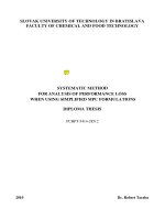
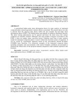
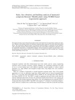
Consider a bending plate with the mid-surface of area A as shown in Fig. 1. The plate is subjected
to loadings q normal to the mid-surface. According to the Reissner-Mindlin thick plate theory, the
translational displacements u, v, w related to the x-, y-, z-directions are determined by [1]
u (x, y, z) = zβ x (x, y) ;
v (x, y, z) = zβy (x, y) ;
w (x, y, z) = w0 (x, y)
(1)
where w0 , β x , βy are respectively the deflection and the rotations of the mid-surface about y- and x-axis
with positive directions as shown in Fig. 1.
The mid-surface is discretized by the 3-node triangular elements. The displacements of the midsurface are approximated by [14]
3
w0 =
3
Ni wi ;
i=1
βx =
3
Ni θyi ;
i=1
46
βy = −
Ni θ xi
i=1
(2)
u ( x, y, zu)( x=, yz, b
byy((xx, y, )y; )w; (w
z )x=( zxb, xy()x;, yv) ;( x
v ,( xy,,yz, z))== zzb
x, (yx
, z,)y=, zw)0 (=x, w
y )0 ( x, y )
(1)
(1)
here w0,here
bx, wb0,y bare
and
rotations
the mid-surface
are respectivelythe
the deflection
deflection and
the the
rotations
of the of
mid-surface
x, by respectively
about y- about
and x-axis
with
positive
directions
asshown
shown
in Fig.
y- and x-axis
with
directions
Fig.
1. in1.
Thanh,
C.positive
D., et al.
/ Journal of as
Science
andin
Technology
Civil Engineering
of
loadings
andthe
thepositive
positive Figure
2.
3-node
triangular
plateelementplate
Figure 1.Figure
Definition
of loadings
and
positive
Figure
2. 3-node
The 3-node
triangular
Figure1.1.Definition
Definition
of loadings
and
the
Figure
2. The
The
triangular
plate
and its
displacements
of
the
mid-surface
of
the
positive
directions
of
the
nodal
displacements
displacements
of mid-surface
the mid-surfaceof
of the
the
element
and its
positive
directionsdirections
of
displacements
of the
element
and
its positive
of
Reissner-Mindlin plate
Reissner-Mindlin
plate
the nodal
displacements
Reissner-Mindlin
plate
the nodal
displacements
The
mid-surfacerespectively
isdiscretized
discretized
by
3-node
triangular
elements.
The
The
mid-surface
by the
the
3-node
elements.
The
in which
wi , xi , yi areis
the deflection
and rotations
oftriangular
node i with the
positive directions
displacements
of
the
mid-surface
are
approximated
by
[12]
displacements
the
are approximated
by [12]
defined inof
Fig.
2; mid-surface
and the shape functions
are
3
3
3
3
33
(2)
N w ; bx = N
; by (x
=-ồ NNiqiq
(2)
w0 = ồwN
qNiq;1yi b
ồ
0 =
y=
iw
i ; bi x i = ồ
Nồ
x y xi)xi+ (y2 y3 ) x + (x3 x2 ) y
1i =yi
2 y3ồ
i =1
ii==11 3 2
i =1
i =1 i =1
2Ae
1
which
, yi
qxi,are
qyi are
(x3the
) x +rotations
(x1 of
N2respectively
=
ythe
x1 y3 ) + (y3and
yand
xnode
(3)
in whichin w
, iq
respectively
deflection
nodethei with the
i, qxiw
1 deflection
1rotations
3 ) y ofi with
2Ae
directions
defined
in Fig.2;2;and
and the
functions
are are
positive positive
directions
defined
in Fig.
theshape
shape
functions
1
(x1 y2 x2 y1 ) + (y1 y2 ) x + (x2 x1 ) y
N3 =
1
2A
1
ộ(x2 x
y3 x3 y+2 )(+y( ye- y ) x + ( x3 - x2 x
) 2y ựỷ) y ỷự
N1 = N1 ởộ=( 2xA
2 yở
3
3 y2 )
2 2 y33) x + ( x
3
e
2
A
e
where xi , yi are the nodal coordinates of node i as shown in Fig. 2; and Ae is the area of the element.
1
(3)
1N Eqs.
(3)
between
ộở(-x3and
=( x y(1)
x)1 y+3 )the
+y( yrelationships
2 ộ
3 - y1 ) x + ( x1 - x3 ) y ự
ựỷ strains and the nodal displacements are
N 2 =From
xy11 y-3(2),
ỷ ythe
(
3 1
3 - y1 ) x + ( x1 - x3 )
ở
2
A
e
2A
determined
e
1 = 1 ộ( x y - x y ) + ( y - y ) x + ( x - x ) y ự
2 1 /x
1
2
N 3 = N 3
ộở(xx1 y2ở -1 x2
+ ( x2 2 3-1 x
Ni,x
wi
1 0)ỷ y ựỷ 0
3
2 y1 ) + ( yx1 - y2 ) x
2 Ae
2 Ae
y
0 Ni,y 0
y = z
xi = z
=z
Bbi dei
(4)
y
i, yi are
the nodal
Ae is
the area
where
x
coordinates
of
node
i
as
shown
in
Fig.
2;
and
of
i=1
i=1
0
N
N
+
x
/y
i,x in Fig.
i,y
xy nodal coordinates
where xi, yi are the
2; yiand Ae is the area of
x
y of node i as shown
the element.
Bbi
dei
the element.
From (1)
Eqs. and
(1) and
the relationships
relationships between
the strains
and
nodalthe nodal
the and
strains
From Eqs.
(2),(2),the
between
the
wi
3
3
+
w
N
0
N
/x
xz determined
x
0
i,x
i
displacements
are
B d
(5)
=
=
displacements
are determined
=
si ei
xi
yz
y + w0 /y
Ni,x Ni 0
i=1
i=1
yi
ỡ xỹ
ỡ
ộ0
ảb x ảx ỹ ỹ
0
N i , x ự ỡ wựi ỹỡ ỹ
3 ộ0
ỡ e x ỹ ù eỡ
0
N
B
ù
ùảb x ảx
ù
ỳsiùi , x ù wi 3 d
3 ờ
(4)
ù
ù ớ eù
ù Beibi d ei3
ảb ảy ù ý = z ồ ờờ0 - N i , y
0 ỳ ớq xiỳýù= z ồ
(4)
y ý = zớ
ảb y ảyy
= zồ
0
N
0
q
=
z
B
d
ớ e y ý =ùz ớ
ý
ớ
ý
ồ
i
,
y
xi
bi
ei
=1 ờ
i =1
ù
ùảb B ảyof
ù i i=strains
ùq ỳù
ờ
ỳ
g
+
ả
b
ả
x
0
N
N
1
i
=
1
where
the
gradients
the
in-plane
are
given
by
ùg ù ợ xyùỵảb ợảy x+biảb ảy x ù ỵ
ù
i,x
i , y ỷ ợ yiỳỵù
ở"##
ờ0 #
-$###
N
N!
%
y
i,x
i , y ỷ ợq yi ỵ
ợ xy ỵ
ợ x
ỵ
ở"##
!
#
%
d
B $###
0
b c
c dei
0
B0bi 0
0 0 b
1
1
1
0 a d
0 d
0 a 0 (6)
0 ; Bb2 =
0 ; Bb3 =
Bb1 =
2Ae
2Ae
2Ae
0 cb da
0 c d
0 b
a
bi
ei
in which a = x2 x1 , b = y2 y1 , c = y3 y1 , d =3x3 x1 .
With the approximation of the transverse3shear strains given by Eq. (5), there is always existence
of the transverse shear strains in analyzed plates. In other words, the pure 3-node triangular element
cannot be used for analysis of thin plates in which there are not the transverse shear strains according
47
Thanh, C. D., et al. / Journal of Science and Technology in Civil Engineering
to the Kirchhoff-Love thin plate theory. To be employed for both thin and thick plates, from the
mixed interpolation of tensorial components approach the transverse shear strains in Eq. (5) are reinterpolated to be linear variations corresponding to the three edge directions of the element but be
constant on the edges. The interpolations of the transverse shear strains connect the displacement
approximations at tying points located at the mid-edges. The assumed transverse shear strains have
been designed by Lee and Bathe [6] for the continuum mechanics based 3-node triangular shell finite
elements, namely MITC3 technique to remove the shear locking. As a result, the transverse shear
strains in Eq. (5) can be rewritten as
3
MITC3
γ xz
MITC3
γyz
=
B MITC3
dei
si
(7)
i=1
in which by using one Gaussian quadrature point located at the centroid of the element, B MITC3
si
have been derived by Chau-Dinh et al. [10] in the explicit formulation, which only depends on nodal
coordinates, as follows
1
2Ae
1
=
2Ae
1
=
2Ae
MITC3
B s1
=
MITC3
B s2
MITC3
B s3
(b − c) (b + c)/6
b−c
Ae + (d − a) (b + c)/6
d − a −Ae − (b − c) (a + d)/6
− (d − a) (a + d)/6
c −bc/2 + c (b + c)/6 ac/2 − d (b + c)/6
−d bd/2 − c (a + d)/6 −ad/2 + d (a + d)/6
−b −bc/2 − b (b + c)/6 −bd/2 + a (b + c)/6
a −ac/2 + b (a + d)/6 ad/2 − a (a + d)/6
(8)
The constitutive relations between the stresses and the strains in the isotropic linear plates give
εx
0
0
σx
3
1 v
1 v
Ez
E
εy =
v 1
v
1
0
0
σ
Bbi dei
(9)
=
y
2
2
τ 1 − v 0 0 (1 − ν)/2 γ 1 − v 0 0 (1 − ν)/2 i=1
xy
xy
τ xz
τyz
=
E
2(1 − v)
MITC3
γ xz
MITC3
γyz
=
E
2(1 − v)
3
B MITC3
dei
si
(10)
i=1
with the Young’s modulus E and the Poisson’s ratio v.
The total potential energy of the plate subjected to the normal loadings q is expressed in matrix
notation as [14]
h/2
h/2
σx
kh2
1 MITC3 MITC3
1
τ xz
σy
dzdA+ 2
ε x εy γ xy
γ xz
γyz
dzdA− wqdA = 0
Π=
2
τyz
2
2
h + αhe
τ
xy
A −h/2
A
A −h/2
(11)
where the shear correction k is 5/6; the stabilized factor α is 0.1; and he is the maximum length of the
element’s edges [15].
Using Eqs. (4), (7), (9), and (10), the total potential energy is written by
Ne
Ne
Ne
1 T
1 T
T
MITC3 T
MITC3
Π=
de Bb Db Bb dA de +
de
Bs
DsBs
dA de −
dTe
NqdA = 0
2
2
e=1
e=1
e=1
Ae
Ae
Ae
(12)
48
Tp chớ Khoa hc Cụng ngh Xõy dng NUCE 2019
Tp chớ Khoa hc Cụng ngh Xõy dng NUCE 2019
Thanh, C. D., et al. / Journal
of Science and Technology in Civil Engineering
T
MITC 3
MITC 3
k = ũ TTb Db Bb dA + ũ ( MITC
3 )T D s MITC
3 dA
sMITC3
s
MITC3
k ee =
Db1b BbBdb2
A +Bũb3
D
dAB MITC3 B MITC3 ]; de = [dT dT dT ]T ; N(16)
(
)
s
s
s
in which
BbũAe=b[B
];
B
=
[B
=
Ae
s
e1
e2
e3
s1
s2
s3
Ae
Ae
[N1 0 0 N2 T 0 0 N3 0 0]TMITC
and T
MITC 3
= D B A + s 33 )T Ds MITC
A
= Tbb DbbBbb Aee + (( sMITC
Ds ss 3 Aee
)
0
1 v
Eh3
1 assembled
0
Db =
D v and
with
D
=
and
F
is
the
global
load
vector
from
the
element
load vectors
from the element
and F is the global load vector
and assembled
12 1 v2load vectors
0 0 (1 v)/2
=
ffee =
NqdA
ũũ NqdA
Ae
Ae
Ds =
kEh3
h2 + h2e 2(1 + v)
1 0
0 1
(16)
(13)
(17)
(17)
(14)
2.2. ES-MITC3
ES-MITC3 plate
plate element
element
2.2.
Differentiating in Eq. (12) with respect to de and equating each term to zero to minimize , the
In the
theequilibrium
edge-based
smoothed
FEM
[5],
strain fields
fields are
are averaged
averagedon
ondomains
domainsofof
discretized
equations
are obtains
as[5],
follows
In
edge-based
smoothed
FEM
strain
two adjacent
adjacent elements.
elements. Particularly,
Particularly, the
the edge-based
edge-based smoothed
smootheddomains
domainsare
aredefined
definedby
by
two
Kd = F
(15)
straight lines
lines which
which connect
connect the
the edge's
edge's nodes
nodes with
with the
the centroids
centroids of
of two
two elements
elements
straight
where d is the nodal displacements of the plate; K is the global stiffness matrix and assembled from
sharing this
this edge
edge as
as shown
shown in Fig. 3. Therefore, the ES-MITC3 plate element [8] is the
sharing
the element stiffness
matrices in Fig. 3. Therefore, the ES-MITC3 plate element [8] is the
MITC3 one
one in
in which
which the
the strain
strain fields
fields given
given by
by Eqs.
Eqs. (9)
(9) and
and (10)
(10) are
are smoothed
smoothedasas
MITC3
T
MITC3 T
MITC3
k
=
B
D
B
dA
+
B
D
B
dA
b
b
s
e
follows
s
s
b
follows
Ae
Ae
!
ỡ ee!x ỹ
ỹ
ỡee x ỹỹ
!
ỡ
ỡ
!
x
x
ỹ 11 B MITC3
ỡtt ỹT D s B MITC3 Ae
1 ùù ùù = BTỡỡD
ù !! ù
ù
ttxz
1
ù
bxzBỹb A=e +
sỡớ xzxzỹý d
b
!
!
e
=
e
d
A
;
!
ớ
ý
ớ
ý
ớ
ý
!
!
e
=
e
d
A
;
=
dAA s
y
ũ
ớ yy ý
ớ t! ý
ũ
ũ
! ớ y ý
! ớtt ý
A
A
!
!
t
!
yz
yz
A
A
ợ yzthe
Ak ù
ùisg!theù
ù
ùg vector
kk A
kk AA
ợợ yz ỵỵ
ỵỵ element load vectors
ùù
k
kk ợ
and Fù
xy ỵ global load
ợg xy
ợg xyxy ỵỵ and assembled from
ợ
ỵ
ợ
!
fe =
NqdA
here Akk is the edge-based
edge-based smoothed
smoothed domain
domain
ofedge
edge"k".
"k".
of
(16)
(18)
(18)
(17)
Ae
Using the relationships
relationships between
between the
the strain
strain fields
fields and
and nodal
nodaldisplacements
displacementsgiven
given
2.2. ES-MITC3 plate
element
(10), the
the smoothed
smoothed strains
strains fields
fieldsin
inEq.
Eq.(18)
(18)can
canbe
beexpressed
expressed
by Eqs. (9) and (10),
Figure
Edge-based
smoothed
Edge-based
smoothed
domains
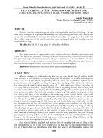
Figure 3.3.Edge-based
smoothed
domainsdomains
for a plate
discretized
by
3-node
elements
for a plate discretized
discretized by
by 3-node
3-node elements
elements
Figure
smoothed
domains
Figure
4.Node-based
Node-based
smoothed
domains
Figure
4.4.
Node-based
smoothed
domains for
a plate
discretized
by
3-node
elements
for
foraaplate
platediscretized
discretizedby
by3-node
3-nodeelements
elements
!
ỹ
e x edge-based
11 vv
00 [7],ựựstrainN!! fields are
ộộsmoothed
Inỡthe
FEM
averaged on domains of two adjacent eleEz
ù !x ù
ờờ
ỳỳ 11 N ổổ AAee 33 ee ửử
Ez
(19)
(19)
!
e yy ý =
v
1
0
B
ments.ớParticularly,
the
edge-based
smoothed
domains
are
defined
!
v
1
0
B
ồ
ồ
22 ờ
ỳỳ A ồỗỗ 3 ồ bibiddeieiữữby straight lines which connect the
ờ
1
v
!
e
=
1
i
=
1
ố
ứ
1
v
3
A
k
1 ố $###
i =1
k e =sharing
ùnodes
ù with theờởờcentroids
%
edgesù
this edge
g!xy ù
0 0 1of-two
n elements
2 ỳ "###
%ứas shown in Fig. 3. Therefore, the
!!$###
ợ
ỵ
ở 0 0 ((1 -n )) 2ỷỳỷ "###
ợg xy
ỵ
BB
dd
ES-MITC3 plate element [10] is the MITC3 one in which the strain fields given by Eqs. (9) and (10)
!!
!!
3
are smoothed
ỡ
ỹ as follows
E
11 NN ổổ A
ửử
ỡtt xz
Aee 3 B MITC
E
(20)
xz ỹ =
MITC3,
3,ee
(20)
!
!
ớ
ý
ồ
ồ
!
sisi d
eieiữ
B
d
ỗ
ớt!yz ý = 2(1 -
ồ
ồ
ỗ
ữ
v
)
3
A
x
x
e
=
1
i
=
1
ố
ứ
t
kk e =1 ố 3 i =
v
)
A
ợ
1
ứ
"###
#
$####
%
ợ yz ỵ
ỵ 2(1 -
1
1
"###
xz
xz
#
!$####
dA; %
=
dA
(18)
=
y
B!
d y
B
d
yz
yz
Ak
A
k
xy
xy
Ak
Ak
66
49
ee
k k
bk k
b
e
e
k k
sk k
s
Thanh, C. D., et al. / Journal of Science and Technology in Civil Engineering
where Ak is the edge-based smoothed domain of edge “k”.
Using the relationships between the strain fields and nodal displacements given by Eqs. (9) and
(10), the smoothed strains fields in Eq. (18) can be expressed
ε
0
Ne
1 v
3
x
A
1
Ez
e
e
v
1
0
B
d
=
(19)
ε
y
bi ei
2
3
1
−
v
γ
A
e=1
i=1
(1
k
0
0
−
ν)/2
xy
k
B b dk
τ xz
τyz
1
E
=
2(1 − v) A
k
Ae
3
e=1
Ne
3
i=1
B MITC3,e
dei
si
(20)
k
B s dk
in which Ak is the area of edge-based smoothed domain “k”; N e = 1 for edge “k” on the boundary
k
k
and N e = 2 for the others; Bb , B s are respectively the gradient matrices of the in-plane and transverse
shear smoothed strains; and dk is the nodal displacements related to the smoothed domain “k”.
Substituting Eqs. (19) and (20) into the total potential energy in Eq. (11) and following the standard FEM procedure, the equilibrium equations of the plate discretized by the ES-MITC3 elements
are rewritten as
Kd = F
(21)
where K is the smoothed global stiffness matrix and assembled from the edge-based smoothed stiffness matrices
k T
k T
k
k
kk = Bb Db Bb Ak + B s D s B s Ak
(22)
2.3. NS-MITC3 plate element
According to the node-based smoothed FEM [7], strain fields are averaged on domains of elements sharing nodes. These smoothed domains are defined by straight lines connecting the edges’
midpoints with the centroids of node-sharing elements as demonstrated in Fig. 4. As a result, the
strain fields in Eqs. (9) and (10) are smoothed on the node-based smoothed domains as follows [11]
ε
εx
x
1
1
τ xz
τ xz
ε
=
dA;
=
dA
(23)
ε
y
y
τyz
τyz
γ
γ
Al
A
l
xy
xy
Al
Al
where Al is the smoothed domain of node “l”.
Substituting the strain – nodal displacement relations in Eqs. (9) and (10) into the Eq. (23), the
node-based smoothed strains are rewritten
εx
0
Ne
1 v
3
A
Ez
1
e
e
v
1
0
B
d
=
(24)
ε
ei
y
bi
1 − v2 0 0 (1 − ν)/2 Al e=1 3 i=1
γ xy
l
Bb dl
50
tandard
FEM using
procedure,
the discretized
equations
the plate
simulated
Similarly,
the expressions
of the equilibrium
nodal smoothed
strains of
in Eqs.
(24) and
25)the
forNS-MITC3
the strain energy
in the
potential energy in Eq. (11) and following the
by
elements
cantotal
be obtained
tandard
! FEM procedure, the discretized equilibrium equations of the plate simulated
Thanh, C. D., et al. / Journal of Science and Technology in Civil Engineering
Kd = F
by the NS-MITC3 elements can be obtained
!
Ne
(26
3
Ae
E
1matrix
τ xz stiffness
MITC3,e
here !K is the smoothed global
and
assembled
from the (25)
node-based
=
B
d
ei
(26)
Kd = F
τyz
2(1 − v) A e=1 3 i=1 si
l
moothed
stiffness
matrices
!
l
here K is the smoothed global stiffness matrix and Bassembled
from the node-based
l
sd
!
!l T
!l !
!l T
!l !
moothed
k l =stiffness
( Bb ) Dmatrices
b Bb Al + ( B s ) Ds B s Al
in which Al is the area of node-based smoothed domain “l”; N e and dl are respectively number of
(27
l
l
!
!l T
!l !
!l T
!l !
elements
andBthe
nodal
displacements
belonging to the smoothed domain “l”; and Bb , B s are the
(27)
k
=
B
D
A
+
B
D
B
A
l
b
b b l
s
s s l
2.4. ES+NS-MITC3
element
gradient matricesplate
of the in-plane
and transverse shear smoothed strains, respectively.
( )
( )
Similarly, using the expressions of the nodal smoothed strains in Eqs. (24) and (25) for the strain
2.4. ES+NS-MITC3
plate
In the
ofelement
combining
ES-following
and the
NS-FEM,
theprocedure,
strain thefields
energyapproach
in the total
potential
energy in Eq. the
(11) and
standard FEM
dis- of the
cretized element
equilibrium equations
of the
plate simulated
by theportion
NS-MITC3of
elements edge-based
can be obtained
MITC3
plate
now
smoothed
In the
approach of are
combining
the ES- on
and aNS-FEM,
thethe
strain fields of smoothed
the
Kd
=
(26) 5(b). To
domains
and element
the otherare
of now
the node-based
smoothed
as edge-based
illustrated in
Fig.
MITC3 plate
smoothed on
a Fportionones
of the
smoothed
domains
the otherdomains
of the node-based
onesNS-ones,
as illustrated
Fig. 5(b).edge
To ed i
build
theand
smoothed
including smoothed
the ES- and
eachinelement's
where K is the smoothed global stiffness matrix and assembled from the node-based smoothed stiffness matrices
build theinto
smoothed
domains
theT with
ES- and
each element's edge ed is
divided
3 segments
as including
in Fig. 5(b)
the NS-ones,
ratio
l
l
l T
l
Bb Alratio
+ Bs
divided into 3 segments
as in Fig. k5(b)
l = Bwith
b Dbthe
ed
L
ed
L1ed = Led
; Led
3 = bLed
2 = (1 - b ) L
ES+NS-MITC3
element ed
2; Ledplate
L1ed =2.4.
Led
3 = b
2 = (1 - b ) L
(27)
D s B s Al
(28)
(28
2
In the approach
of combining the ES- and NS-FEM, the strain fields of the MITC3 plate element
ed
ed
ed
here Led are
b Î [0,1]
is a scale
factordomains
used and
to the
tune
the
contribution
of
now+
smoothed
of the edge-based
smoothed
other
of the
node-based
=L
L +edLon3 a; portion
ed
ed1
ed 2
here L =smoothed
; b Î [0,1]
a scale
factor
used todomains
tune the
contribution
L1 + Lones
L3illustrated
in Fig.is5(b).
To build
the smoothed
including
the ES- and of
NS-the
2 + as
node-based
smoothed
domains
in
the
ES+NS-domains.
It
means
that
if
b = 0,
ones, each element’s edge ed is divided into 3 segments as in Fig. 5(b) with the ratio
the
the
node-based smoothed domains in the ES+NS-domains. It means that if b = 0, the
ES+NS-domains become the edES-domains,
and if b ed= 1, the ES+NS-domains are
Led
(1 −=β)1,
ES+NS-domains become the ES-domains,
; L2edif= b
L the ES+NS-domains
(28)are
L1 = L3ed = β and
2
purely
NS-ones.This
Thisapproach
approach
is also
called
the
bFEM
[10,11].
purely NS-ones.
is also
called
the b
FEM
[10,11].
Figure 5.
(a)
(a)
(a)
(b)
(b)
(b)
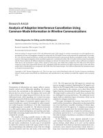
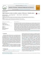
Figure 5. (a) Edge and node-based smoothed domains for a plate discretized by 3-node elements;
(a)
and
node-based
smoothed
domains
forsmoothed
a plateareas
discretized
3-node
(b) Edge
Definition
of the
ES- (line hatching)
and the NS(dot hatching)
of a triangularby
element
Figure 5. (a) Edge and node-based smoothed domains for a plate discretized by 3-node
elements; (b) Definition of the ES- (line hatching)
and the NS- (dot hatching)
51
elements; (b) Definition
of
the
ES(line
hatching)
and the NS- (dot hatching)
smoothed areas of a triangular element
smoothed
areas of a triangular
element
ed
ed
ed
From the middle segments L2 and the end segments L1 and L3 , the ES-domains and
Thanh, C. D., et al. / Journal of Science and Technology in Civil Engineering
where Led = L1ed + L2ed + L3ed ; β ∈ [0, 1] is a scale factor used to tune the contribution of the node-based
smoothed domains in the ES+NS-domains. It means that if β = 0, the ES+NS-domains become the
ES-domains, and if β = 1, the ES+NS-domains are purely NS-ones. This approach is also called the
βFEM [12, 13].
From the middle segments L2ed and the end segments L1ed and L3ed , the ES-domains and NSdomains are respectively constructed for elements having common edges and nodes to have the
smoothed areas of
Aˆ k = β2 Ak ; A˜ l = 1 − β2 Al
(29)
Consequently, the strain fields in Eqs. (9) and (10) averaged on the ES+NS-domains are determined by
εˆ x
εˆ y
γˆ
xy
ε˜ x
ε˜ y
γ˜
xy
1
=
Aˆ k
1
=
A˜ l
Aˆ k
A˜ l
εx
εy
γ
xy
εx
εy
γ
xy
dA;
τˆ xz
τˆ yz
dA;
τ˜ xz
τ˜ yz
1
Aˆ k
=
1
A˜ l
=
τ xz
τyz
dA
(30)
τ xz
τyz
dA
(31)
Aˆ k
A˜ l
Using Eq. (29) and substituting Eqs. (9), (10) into Eqs. (30), (31), the relationships between ESand NS-strain fields and the nodal displacements in the ES+NS-MITC3 plate element can be derived
εˆ x
εˆ y
γˆ
xy
Ez
=
1 − v2
0
1 v
0
v 1
0 0 (1 − ν)/2
1
β2 A
Ne
k e=1
Ae
β2
3
3
i=1
Bebi dei
(32)
k
Bb dk
τˆ xz
τˆ yz
1
E
=
2(1 − v) β2 A
k
Ne
e=1
Ae
β2
3
3
i=1
B MITC3,e
dei
si
(33)
k
B s dk
ε˜ x
ε˜ y
γ˜
xy
Ez
=
1 − v2
0
1 v
0
v 1
0 0 (1 − ν)/2
1
1 − β2 Al
1 − β2 Ae
3
e=1
Ne
3
i=1
Bebi dei
(34)
l
B b dl
τ˜ xz
τ˜ yz
E
1
=
2(1 − v) 1 − β2 A
l
1 − β2 Ae
3
e=1
Ne
3
i=1
B MITC3,e
dei
si
(35)
l
B s dl
And then, from the total potential energy expressed in the smoothed strain fields given in Eqs.
(32)–(35), the equilibrium equations of the plates discretized by ES+NS-MITC3 elements can be
written
KES +NS d = F
(36)
52
!
k" l = Bbl
( )
T
!
!
" + Bl
DbBbl A
l
s
( )
T
!
!
" = (1 - b 2 ) k
Ds Bls A
l
l
3. Numerical examples
Thanh, C. D., et al.In
/ Journal
of Science the
and Technology
Civil Engineering
this section,
accuracyin and
convergence
of the ES+NS-MITC
via the global
patch stiffness
test and
some
plate
where K
is the edge- be
and evaluated
node-based smoothed
matrix
and benchmark
assembled from
the problem
smoothed stiffness matricesprovided by the ES+NS-MITC3 element are compared with similar kin
k T
k
k
like ES-DSG3
[6],k TMITC3
[4], ES-MITC3 [8] and NS-MITC3 [
kˆ k = Bb Db Bb Aˆ k + B s D s B s Aˆ k = β2 kk
(37)
examples, we choose the scale factor b = 0.6. To compare with r
l T
l
l T
and
moments
atl Athe
are normalized by
2
˜kdeflection
˜
˜ = plate
= B D B A + B DB
1 − βcenter
k
(38)
ES +NS
l
b
b b l
wc = wc
3. Numerical examples
s
s
s l
l
100 D
10
; Mc = Mc 2
4
qL
qL
In this section, the accuracy
and convergence
of the ES+NS-MITC3 element will be evaluated
3.1. Patch
test
via the patch test and some benchmark plate problems. The results provided by the ES+NS-MITC3
Consider
patch test
a 0.01 [8],
m-thick
rectangular
plate with the
element are compared with similar
kinds ofaelements
likebe
ES-DSG3
MITC3
[6], ES-MITC3
2
[10] and NS-MITC3 [11]. In
all m
the´examples,
the scale
factorEβ == 10
0.6.7 kN/m
To compare
0.24
0.12 m, we
thechoose
Young's
modulus
andwith
the Poisson's
references, the deflection and moments at the plate center are normalized by
The plate is discretized by 3-node triangular elements as in Fig. 6
2
100D of ¯the plate
10
deflection
+ y2 ) / 200 m
w¯ c = equation
wc
; Mc = Mc 2w = (1 + x + 2y + x + xy (39)
4
qL can reproduce
qL the deflection and moments at node 5
MITC3 element
Table 1. It means that the ES+NS-MITC3 plate element passes the patch
3.1. Patch test
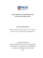
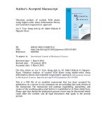
Consider a patch test be a 0.01 m-thick rectangular plate with the dimension of 0.24 m ×
0.12 m, the Young’s modulus E = 107 kN/m2
and the Poisson’s ratio v = 0.25. The plate is discretized by 3-node triangular elements as in Fig.
6 [8]. With the deflection equation of the plate
w = (1 + x + 2y + x2 + xy + y2 )/200 m, the ES+NSMITC3 element can reproduce the deflection and
moments at node 5 as shown in Table 1. It means
that the ES+NS-MITC3 plate elementFigure
passes 6.
theNodal coordinates
Figure 6. Nodal
coordinates of
elements for the patc
of elements
discretized
discretized
for
the
patch
test
patch test.
Table 1. Deflection and moments of the patch test at node
Table 1. Deflection and moments of the patch test at node 5
Methods
w5 (×10−2 m)
θ x5Methods
(×10−2 rad.)
ES+NS-MITC3+
Exact solution
0.6422
0.6422
1.1300
1.1300
ES+NS-MITC3+
Exact solution
w5
θy5 (×10−2 rad.)
-2
(´10
−0.6400
−0.6400
qx5
M x5 (kNm/m)
qy5
My5 (kNm/m)
Mx5
M xy5 (kNm/m)
-2
m) (´10
(´10-2 rad.)
−0.0111rad.) −0.0111
0.6422
0.6422
3.2. Simply supported plate under uniform distributed loading
−0.0111
1.1300
1.1300
−0.0111
-0.6400
-0.6400
(kNm/m)
−0.0033
−0.0033
My5
(kNm/
-0.0111
-0.01
-0.0111
-0.01
3.2. Simply
loading
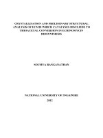
A square plate of the length
L and supported
the thicknessplate
h is under
simply uniform
supporteddistributed
on the boundary
and
2
subjected to the uniform loading q = 1 kN/m as illustrated in Fig. 7. The material properties are E
A square plate of the length L and the thickness h is simply sup
= 1092000 kN/m2 and v = 0.3. The plate is modelled by 2 × N × N triangular elements in which N is
and subjected to the uniform loading q = 1 kN/m2 as illustr
number of elements on eachboundary
edge.
2 thin plate with
The accuracy and convergence
of the ES+NS-MITC3
are studied
for the
The material
properties areelement
E = 1092000
kN/m
and n = 0.3. The plate
the ratio h/L = 0.001 and the thick one with h/L = 0.1, and the meshes of N = 4, 8, 12, and 16.
53
10
Tạp chí Khoa học Công nghệ Xây dựng NUCE 2019
C. D., etinal.which
/ Journal N
of Science
and Technology
in Civil Engineering
2´N´N triangularThanh,
elements
is number
of elements
on each edge.
Figure
plate simply
simply supported
supported on
on all
all edges
edges and
and subjected
subjectedto
touniform
uniform
Figure 7.
7. Square
Square plate
distributed
loading, and
and regularly
regularly meshed
meshed by
by NN == 44 on
on each
eachplate's
plate'sedge
edge
distributed loading,
The
and convergence
convergence of
of the
the ES+NS-MITC3
ES+NS-MITC3 element
element are
are studied
studied for
for
The accuracy
accuracy and
the
the ratio
ratio h/L
h/L == 0.001
0.001 and
and the
the thick
thick one
one with
with h/L
h/L == 0.1,
0.1, and
and the
the
the thin
thin plate
plate with
with the
meshes
8, 12,
12, and
and 16.
16.
meshes of
of N
N=
= 4,
4, 8,
Figure
7. Square
plate simply
supportedat
on the
all edges
subjected
to uniform
loading, and
The
normalized
deflections
plateandcenter
provided
bydistributed
the ES+NS-MITC3
The7.normalized
deflections
at the plateoncenter
provided subjected
by the ES+NS-MITC3
Figure
Square plate
simplymeshed
supported
edges
to uniform
regularly
by N = 4 onall
each
plate’sand
edge
element for the ratio h/L = 0.001 and
and h/L
h/L == 0.1
0.1 are
are demonstrated
demonstrated in
in Fig.
Fig. 8.8. In
In both
both
distributed loading, and regularly meshed by N = 4 on each plate's edge
cases
of the plate
thickness,
theplate
convergence
curve
given
by the
the ES+NS-MITC3
ES+NS-MITC3
The normalized
deflections
at the
center provided
by given
the ES+NS-MITC3
element for the
convergence
curve
by
ratio
h/L =
0.001
andand
h/L
= 0.1ofare
in
Fig.
8. In both elements.
cases
of the
platestudied
thickness,
The
accuracy
convergence
of the ES+NS-MITC3
element
are
element
lies
between
those
thedemonstrated
ES-MITC3
and
NS-MITC3
elements.
Therefore,
thefor
ES-MITC3
and
NS-MITC3
Therefore,
the
thedeflection
convergence
curve
given
by
the
ES+NS-MITC3
element
lies
between
those
of
the
ES-MITC3
the the
ES+NS-MITC3
element
approaches
to one
the analytical
analytical
solution
[14]the
the thin plate ofwith
ratio h/L = element
0.001 and
the thick
with h/L solution
= 0.1, and
approaches
to
the
[14]
and NS-MITC3 elements. Therefore, the deflection of the ES+NS-MITC3 element approaches to the
moreofrapidly
ES-MITC3
and
NS-MITC3
elements.elements.
However,
the
those
of
ES-MITC3
NS-MITC3
elements.
However,
the
meshes
N
= 4, than
8,
12,
andrapidly
16.thethan
analytical
solution
[16]
more
those of theand
ES-MITC3
and NS-MITC3
However,
and
NS-domains
does
not improve
improve
theofresults
results
ofas
theESESNS-domains
does
not
the
of
theproposed
proposed combination
combination ofofthe
andand
NS-domains
does not
improve
the results
moments
The
normalized
deflections
at
the
plate
center
provided
by
the
ES+NS-MITC3
illustrated
in as
Fig.illustrated
9.
moments
in Fig. 9.
element for the ratio h/L = 0.001 and h/L = 0.1 are demonstrated in Fig. 8. In both
cases of the plate thickness, the convergence curve given by the ES+NS-MITC3
element lies between those of the ES-MITC3 and NS-MITC3 elements. Therefore, the
deflection of the ES+NS-MITC3 element approaches to the analytical solution [14]
more rapidly than those of the ES-MITC3 and NS-MITC3 elements. However, the
proposed combination of the ES- and NS-domains does not improve the results of
moments as illustrated in Fig. 9.
(a) h/L =Tạp
0.001chí
h/L = 0.1
2019
Tạp
chí Khoa học Công nghệ Xây dựng NUCE (b)
(a) h/L = 0.001
(b)
(b) h/L
h/L==0.1
0.1
Figure 8. Convergence of the normalized deflections at the center of the simply supported plates
under uniform
distributed loading
deflections
at
Figure 8. Convergence of the normalized
normalized
deflections
at the
the center
center of
ofthe
thesimply
simplysupported
supported
plates under uniform
uniform distributed
distributed loading
loading
(a) h/L = 0.001
11
11
(b) h/L = 0.1
Figure 8. Convergence of the normalized deflections at the center of the simply supported
(a) h/L =plates
0.001
(b) h/L = 0.1
(a) h/L
h/L == 0.001 under uniform distributed loading
(b) h/L = 0.1
(a)
Figure 9. Convergence of the normalized moments at the center of the simply supported plates
under uniformmoments
distributed loading
Figure 9.
9. Convergence
Convergence of the normalized
Figure
at the center of the simply supported
54 distributed loading
plates under uniform
3.3. Simply
Simply supported
supported Morley plate subjected to uniform distributed loading
3.3.
Consider the
the rhombus Morley plate [15] of the length L = 100 cm and the
Consider
3.3. Simply supported Morley plate subjected to uniform distributed loading
Consider the rhombus Morley plate [15] of the length L = 100 cm
thickness h = 1 cm as shown in Fig. 10. The plate is simply supported on all
Thanh, C. D., et al. / Journal of Science and Technology in Civil Engineering
and subjected uniform distributed loading q = 0.1 N/cm2. The Young's mod
2 uniform distributed loading
3.3. Simply supported Morley plate
subjected
109200
N/cmto
and the Poisson's ratio n is 0.3.
Consider the rhombus Morley plate [17] of the
length L = 100 cm and the thickness h = 1 cm as
shown in Fig. 10. The plate is simply supported
on all the edges and subjected uniform distributed
loading q = 0.1 N/cm2 . The Young’s modulus E
is 109200 N/cm2 and the Poisson’s ratio v is 0.3.
The Morley plate is discretized by different
meshes of N = 4, 8, 12, and 16, in which N is
the number of elements on each edge of the plate
(Fig. 10). The normalized deflections
and(a)
moFigure 10.
Geometry,Figure
uniform
loading,
and simply supported
10. distributed
Geometry, uniform
distributed
ments at the plate center provided by the proposed
loading,
and
simply
supported
boundary
of the Morley plate with a mesh of Nof=the
4
element and the other reference ones are compared
Morley plate with a mesh of N = 4
in Fig. 11 and Fig. 12, respectively. As
shown
in plate is discretized by different meshes of N = 4, 8, 12, a
The
Morley
these figures, the results of the ES+NS-MITC3
element
average values
of those
given
the(Fig.
ES- 10). The n
which N is the number are
of elements
on each
edge of
the by
plate
Tạp
chí
Khoa
học
Công
nghệ
Xây
dựng
NUCE
2019
MITC3 and NS-MITC3 elements.
The deflection
of the
ES+NS-MITC3
element
well converge
the
Tạp chí deflections
Khoa
học Công
Xây
dựng
NUCE
andnghệ
moments
at the
plate2019
center
provided
by thetoproposed
eleme
reference solution [17]. However, the accuracy and convergence of the moment given by the ES+NSother reference ones are compared in Fig. 11 and Fig. 12 respectively. As
MITC3 are not good due to the bad results provide by the NS-MITC3 element. In this case, we can
these
figures,
results of reduce
the ES+NS-MITC3
value
tune
the scale factor
β to be
nearly
equal
1.0 tothe
dramatically
the overly softelement
behaviorare
of average
the
node-based
smoothed
approach.
node-based
smoothed
approach.
given
by
the
ES-MITC3
and
NS-MITC3
elements.
The
deflection
of
the
node-based smoothed approach.
MITC3 element well converge to the reference solution [15]. However, the
and convergence of the moment given by the ES+NS-MITC3 are not good
bad results provide by the NS-MITC3 element. In this case, we can tune
factor b to be nearly equal 1.0 to dramatically reduce the overly soft behav
12
Figure 11. Convergence of the normalized
deflections
at the center ofof
thethe
Morley
plate
Figure 11. Convergence
normalized
Figure 12. Convergence of the normalized moments
at the
center of the Morley
normalized
Figure 12.
Convergence
of theplate
normalized
deflections at the center of the Morley plate
moments at the center of the Morley
Morley plate
plate
3.4. Clamped circular plate under uniform distributed loading
3.4.
Clamped
circular
plate
Give
a circular
plate with
theunder
radiusuniform
R = 5 mdistributed
clamped onloading
its circumference and subjected to
2
uniformGive
distributed
loading
q =with
1 kN/m
as shown
Fig.
13(a).
The plate
thickness
h with theand
ratio
a circular
plate
the radius
R=
5m
clamped
on its
circumference
circumference
and
h/R = 0.02 and h/R = 0.2 are studied. The isotropic homogeneous
material
of
the
plate
has
E =
subjected to uniform distributed loading q = 1 kN/m22 as shown Fig. 13(a). The
The plate
plate
1092000 kN/m2 , v = 0.3.
thickness
h with the
ratio ofh/R
0.02is meshed
and h/Rby=6, 0.2
areorstudied.
The asisotropic
isotropic
Due to symmetry,
a quarter
the =plate
24, 54
96 elements
shown in
2
Fig.
13(b). The deflections
moments
at the
plate
center solved
ES+NS-MITC3 and other
homogeneous
material and
of the
plate has
E=
1092000
kN/m 2by
, nthe
= 0.3.
reference elements are respectively demonstrated in Fig. 14 and Fig. 15. Numerical results show that
the hybrid model of the ES+NS-MITC3 element can reduce the overly soft behaviors of the NSMITC3 element and the overly stiff behaviors of the ES-MITC3 to rapidly approach the reference
solutions [1] for both thin (h/R = 0.02) and thick (h/R = 0.2) plates.
55
Give a circular plate with the radius R = 5 m clamped on its circumference and
a circular
plate with
radius2 Ras=shown
5 m clamped
on its The
circumference
and
subjected to uniformGive
distributed
loading
q =the
1 kN/m
Fig. 13(a).
plate
2
subjected to uniform distributed loading q = 1 kN/m as shown Fig. 13(a). The plate
thickness h with the ratio h/R = 0.02 and h/R = 0.2 are studied. The isotropic
thickness h with the ratio h/R = 0.02 and 2h/R = 0.2 are studied. The isotropic
homogeneous material ofThanh,
the plate
EJournal
= 1092000
kN/m
, n = 0.3.
C. D., ethas
al.
of Science
and1092000
Technology
in Civil
2 Engineering
homogeneous material
of/ the
plate
has E =
kN/m
, n = 0.3.
Tạpchí
chíKhoa
Khoahọc
họcCông
Côngnghệ
nghệXây
Xâydựng
dựngNUCE
NUCE2019
2019
Tạp
Tạp
Tạpchí
chíKhoa
Khoahọc
họcCông
Côngnghệ
nghệXây
Xâydựng
dựngNUCE
NUCE2019
2019
both thin
thin (h/R
(h/R == 0.02)
0.02) and
and thick
thick (h/R
(h/R==0.2)
0.2)plates.
plates.
both
(a)
(a)
(b)
(b)
(a)
(b)circular plate;
Figure 13. (a) Geometry and loading of the clamped
both
(h/R
=
0.02)
and
thick
(h/R
=
0.2)
plates.
Figure
13.
(a)
Geometry
and
loading
of the clamped circular plate
boththin
thin
(h/R
=
0.02)
and
thick
(h/R
=
0.2)
plates.
(b) A quarter of the plate discretized by 24 triangular elements and symmetric boundaries
Figure
(a) Geometry
anddiscretized
loading of
clamped circular
(b) 13.
A quarter
of the plate
bythe
24 triangular
elementsplate
and symmetric boundaries
(b) A quarter of the plate discretized by 24 triangular elements and symmetric boundaries
Due to symmetry, a quarter of the plate is meshed by 6, 24, 54 or 96 elements as
shown inaFig.
13(b).
deflections
and moments
theorplate
center solved
Due to symmetry,
quarter
of The
the plate
is meshed
by 6, 24,at54
96 elements
as by the
ES+NS-MITC3
and otherand
reference
elements
respectively
demonstrated
shown in Fig. 13(b).
The deflections
moments
at theareplate
center solved
by thein Fig. 14
Numerical
results show
that the hybrid
model of the
ES+NS-MITC3
ES+NS-MITC3 and
andFig.
other15.reference
elements
are respectively
demonstrated
in Fig.
14
element
can
reduce
the
overly
soft
behaviors
of
the
NS-MITC3
element
and
and Fig. 15. Numerical results show that the hybrid model of the ES+NS-MITC3the overly
stiff behaviors of the ES-MITC3 to rapidly approach the reference solutions [1] for
element can reduce the overly soft behaviors of the NS-MITC3 element and the overly
(a) h/R
h/R == 0.02
0.02
(b)
h/R==0.2
0.2
stiff behaviors of the (a)
ES-MITC3
to rapidly approach13the reference (b)
solutions
[1] for
h/R
h/R = 0.02 at the center of the clamped circular
(b) plate
h/R = 0.2
Figure 14.
14. (a)
(a)(a)Deflections
Deflections
correspondingtoto
Figure
center of the clamped circular
plate
(a)h/R
h/R==0.02
0.02at the 13
(b)h/R
h/R==corresponding
0.2
(a)
(b)
0.2
Figure 14. Deflections
the centerof
the24,
clamped
circular
plate corresponding to
differentatmeshes
meshes
6,
54and
and
96elements
elements
different
ofof6,
24,
54
96
different
meshes
ofofof
6,the
24,
and 96 elements
Figure14.
14.(a)
(a)Deflections
Deflections
the
center
the54
clamped
circularplate
platecorresponding
correspondingtoto
Figure
atatthe
center
clamped
circular
differentmeshes
meshesofof6,6,24,
24,54
54and
and96
96elements
elements
different
(a) h/R = 0.02
(b) h/R = 0.2
(a) h/R
h/RMoments
0.02 at the center of the clamped circular plate(b)
(b)
h/R==0.2
0.2 to
(a)
== 0.02
h/R
Figure
15.
corresponding
different meshes of 6, 24, 54 and 96 elements
Figure 15.
15. (a)
(a)
Moments
at the
the center
centerof
ofthe
theclamped
clampedcircular
circular
plate
Figure
at
toto
(a)Moments
h/R==0.02
0.02
(b)plate
h/R=corresponding
=corresponding
0.2
(a)
h/R
(b)
h/R
0.2
different meshes
meshesof
of6,
6,24,
24,54
54and
and96
96elements
elements
different
4. Conclusions
Figure15.
15.(a)
(a)Moments
Momentsatatthe
thecenter
centerofofthe
theclamped
clampedcircular
circularplate
platecorresponding
correspondingtoto
Figure
4.The
Conclusions
4.
Conclusions
different
meshes
24,54
54and
and96
96elements
elements
ofof6,
βFEM, which isdifferent
the
hybridmeshes
approach
of6,24,
the
edge-based
and
node-based smoothed strains,
has been developed for the 3-node triangular MITC3 plate elements. The suggested ES+NS-MITC3
Conclusions
The bbFEM,
FEM, which
which isis the
the hybrid
hybrid approach
approach of
of the
the edge-based
edge-based and
and node-based
node-based
The
4.4.Conclusions
56
smoothed
strains,
has
beenisdeveloped
developed
forapproach
the3-node
3-nodetriangular
triangular
MITC3and
plate
elements.
smoothed
been
for
the
MITC3
plate
elements.
Thestrains,
FEM,has
which
thehybrid
hybrid
the edge-based
edge-based
node-based
The
bbFEM,
which
is the
approach ofofthe
and node-based
The
suggested
ES+NS-MITC3
element
passes
the
test
attenuates
the
The
suggested
ES+NS-MITC3
elementfor
passes
the patch
patch
testand
and
attenuates
theshearshearsmoothed
strains,
hasbeen
beendeveloped
developed
the3-node
3-node
triangular
MITC3
plateelements.
elements.
smoothed
strains,
has
for the
triangular
MITC3
plate
locking
phenomenon.
The
analyses
of
benchmark
problems
show
locking
phenomenon.
The static
staticelement
analyses
of some
some
benchmark
plate
problems
show
Thesuggested
suggested
ES+NS-MITC3
passes
thepatch
patch
testand
andplate
attenuates
theshearshearThe
ES+NS-MITC3
element passes
the
test
attenuates
the
Thanh, C. D., et al. / Journal of Science and Technology in Civil Engineering
element passes the patch test and attenuates the shear-locking phenomenon. The static analyses of
some benchmark plate problems show that the ES+NS-MITC3 element can reduce the overly stiff
and soft behaviors of the purely ES-MITC3 and NS-MITC3 elements respectively. As a result, the
ES+NS-MITC3 element improves the accuracy of the plate deflections and moments as compared
with the ES-MITC3 and NS-MITC3 elements, especially in the cases of coarse meshes.
Acknowledgements
This research is funded by Vietnam National Foundation for Science and Technology Development (NAFOSTED) under grant number 107.02-2017.304.
References
[1] Timoshenko, S. P., Woinowsky-Krieger, S. (1959). Theory of plates and shells. McGraw-hill.
[2] Hai, L. T., Tu, T. M., Huynh, L. X. (2018). Vibration analysis of porous material plate using the first-order
shear deformation theory. Journal of Science and Technology in Civil Engineering (STCE) -NUCE, 12
(7):9–19.
[3] T, T. M., Quoc, T. H., Tham, V. V. (2018). Analytical solutions for the static analysis of laminated composite plates with piezoelectric layers based on Reddy’s higher-order shear deformation theory. Journal
of Science and Technology in Civil Engineering (STCE) - NUCE, 12(4):40–50.
[4] Tessler, A., Hughes, T. J. R. (1985). A three-node Mindlin plate element with improved transverse shear.
Computer Methods in Applied Mechanics and Engineering, 50(1):71–101.
[5] Bletzinger, K.-U., Bischoff, M., Ramm, E. (2000). A unified approach for shear-locking-free triangular
and rectangular shell finite elements. Computers & Structures, 75(3):321–334.
[6] Lee, P.-S., Bathe, K.-J. (2004). Development of MITC isotropic triangular shell finite elements. Computers & Structures, 82(11-12):945–962.
[7] Liu, G. R., Nguyen-Thoi, T. (2016). Smoothed finite element methods. CRC Press.
[8] Nguyen-Xuan, H., Liu, G. R., Thai-Hoang, C., Nguyen-Thoi, T. (2010). An edge-based smoothed finite
element method (ES-FEM) with stabilized discrete shear gap technique for analysis of Reissner–Mindlin
plates. Computer Methods in Applied Mechanics and Engineering, 199(9-12):471–489.
[9] Nguyen-Xuan, H., Rabczuk, T., Nguyen-Thanh, N., Nguyen-Thoi, T., Bordas, S. (2010). A node-based
smoothed finite element method with stabilized discrete shear gap technique for analysis of Reissner–
Mindlin plates. Computational Mechanics, 46(5):679–701.
[10] Chau-Dinh, T., Nguyen-Duy, Q., Nguyen-Xuan, H. (2017). Improvement on MITC3 plate finite element
using edge-based strain smoothing enhancement for plate analysis. Acta Mechanica, 228(6):2141–2163.
[11] Chau-Dinh, T., Nguyen-Van, D. (2016). Static and frequency analysis of laminated composite plates using
the MITC3 elements having the strains averaged on node-based domains (NS-MITC3). In Proceedings
of the National Science Conference on "Composite Materials and Structures: Mechanics, Technology and
Application", 613–620.
[12] Wu, F., Liu, G. R., Li, G. Y., Cheng, A. G., He, Z. C. (2014). A new hybrid smoothed FEM for static and
free vibration analyses of Reissner–Mindlin Plates. Computational Mechanics, 54(3):865–890.
[13] Wu, F., Zeng, W., Yao, L. Y., Hu, M., Chen, Y. J., Li, M. S. (2018). Smoothing Technique Based Beta
FEM (β FEM) for Static and Free Vibration Analyses of Reissner–Mindlin Plates. International Journal
of Computational Methods, page 1845006.
[14] Logan, D. L. (2011). A first course in the finite element method. Thomson.
[15] Lyly, M., Stenberg, R., Vihinen, T. (1993). A stable bilinear element for the Reissner–Mindlin plate model.
Computer Methods in Applied Mechanics and Engineering, 110(3-4):343–357.
[16] Taylor, R. L., Auricchio, F. (1993). Linked interpolation for Reissner-Mindlin plate elements: Part II—A
simple triangle. International Journal for Numerical Methods in Engineering, 36(18):3057–3066.
[17] Morley, L. S. D. (1963). Skew plates and structures. Pergamon Press.
57