- Trang chủ >>
- Khoa học tự nhiên >>
- Vật lý
EFFECT OF COMPLEXING AGENTS ON nife NANOMATERIAL BY ELECTROCHEMICAL METHOD
Bạn đang xem bản rút gọn của tài liệu. Xem và tải ngay bản đầy đủ của tài liệu tại đây (1018.86 KB, 44 trang )
Ghh
VIETNAM NATIONAL UNIVERSITY, HANOI
VNU UNIVERSITY OF SCIENCE
FACULTY OF PHYSICS
NGUYEN KHANH CHI
EFFECT OF COMPLEXING AGENTS ON
NiFe NANOMATERIAL BY
ELECTROCHEMICAL METHOD
Submitted in partial fulfillment of the requirements
for the degree of Bachelor of Science in Physics
(International Standard Program)
HaNoi - 2019
VIETNAM NATIONAL UNIVERSITY, HANOI
VNU UNIVERSITY OF SCIENCE
FACULTY OF PHYSICS
NGUYEN KHANH CHI
EFFECT OF COMPLEXING AGENTS
ON NiFe NANOMATERIAL
BY ELECTROCHEMICAL METHOD
Submitted in partial fulfillment of the requirements
for the degree of Bachelor of Science in Physics
(International Standard Program)
Supervisor: Assoc. Prof. Dr. Le Tuan Tu
HaNoi - 2019
2
ACKNOWLEDGEMENTS
Firstly, I would like to express my sincere gratitude to Assoc. Prof. Dr. Le
Tuan Tu for his valuable guides and advice.
I am profoundly grateful to teachers at Department of Cryogenics, Faculty of
Physics, VNU University of Science for their enthusiastic teaching during those
four years.
I would also like to thank my friends for their advices, sharing, help and
friendship not only in my study but also in my life.
I would like to express my profound and heartfelt thanks to my family. I am
where I am today because of having family’s support in the past time.
Finally, I would like to thank my family for unwavering support and
encouraging me to keep up at work.
Nguyễn Khánh Chi
3
LIST OF NOTATIONS ABBREVIATIONS
Abbreviation
Explanation
Hc
Coercivity
Ms
Saturation magnetization
Mr
Remanent magnetization
B
Magnetic field flux density
H
Magnetic field intensity
NPs
Nanoparticles
VSM
A vibrating sample magnetometer/magnetometry
CV
Cyclic Voltammetry
XRD
X-Ray diffraction
EDS
Energy Dispersive X-ray Spectroscopy
SEM
Scanning Electron Microscopy
CMS
Center of Material Science
VNU
Vietnam National University
4
LIST OF FIGURES
5
CONTENTS
6
INTRODUCTION
For centuries, science has explored and continually redefined the frontiers of
our knowledge. For a recently, we knew the concept of ever smaller scalenanoscaleone billionth of a meter. Nanoparticles are particles with size measured in
nanometers. According to International Organization for Standardization (ISO)
Technical Specification 80004, a nanoparticle is defined as a nano-object with all
three external dimensions in the nanoscale, whose longest and shortest axes do not
differ significantly, with a significant difference typically being a factor of at least 3.
They have greater surface area per weight than larger particles, which causes them
to be more reactive to some other molecules. Nanoparticles are used and being
evaluated for use, in many fields as medicine, manufacturing, materials,
environment, energy and electronics.
In particular, magnetic nanoparticles are useful for a wide range of
applications from data storage to medicines. If subjected to a magnetic field, the
nanoparticles show a high magnetization that is very uniform throughout the
material. The fact thatsoft magnetic nanoparticles can quickly switch magnetization
direction once the external magnetic field is reversed makes them ideal for use in
high-frequency electric circuits used, for example, in mobile phones. In particular,
magnetic oxide nanomaterials, including iron oxide ( Fe 3O4 and γ-Fe2O3), spinel
ferrites (MFe2O4 ; M = Mn, Zn, Cr, Ni, or Co) and hexagonal ferrite ( MFe 12O19,
M=Ba and Sr) are attracting much attention due to their wide application potentials
in advanced magnets, electronic devices, information storage, magnetic resonance
imaging (MRI), and drug-delivery technology. Thus, the synthesis and applications
of nano structured magnetic ferrite has become a particularly important research
field.[20]
Two approaches often represent manufacture of nanomaterials are “topdown” and “bottom–up”. “Top-down” refers to making nanoscale structures by
machining, template and lithographic techniques, whereas “bottom-up”, or
7
molecular nanotechnology, applies to building organic and inorganic materials into
defined structures, atom-by-atom or molecule-by-molecule, often by self-assembly
or self- organization. In particularly, in the second approach, the nanoparticles are
grown using electrodeposition from liquid solution or chemical vapor deposition
(CVD). The synthesis from solution is more advantageous because it can produce
large quantities of nanoparticles with relatively cost low and inexpensive
infrastructure. While vapor growth is used mainly for semiconducting materials,
the deposition from solution is employed for both metallic and semiconducting
structures.[7]
The advanced physical properties of composite coatings quickly became
clear and during the 1990s, new areas such as electrocatalysts and
photoelectrocatalysts were considered. With the emergence of nanostructured
materials over the last decade, electrodeposition techniques have provided a route to
a variety of new nanomaterials. These include nano crystalline deposits, nanowires,
nanotubes, nanomultilayers and nanocomposites. Strengthened composite coatings,
enhanced electrical resistance in printed circuit boards, improved giant
magnetoresistance in memory storage systems and increased microhardness for
microdevices in micro-electro-mechanical systems have been the focus of numerous
studies [7].
In this thesis, the work focused on effect of complexing agents on NiFe
nanomaterial by Electrochemical method.
8
1. CHAPTER 1: MAGNETIC NANOPARTICLES
In this chapter, the basics of nanomagnetics will first be presented followed
by a review on the synthesis and functionalization of magnetic nanoparticles.
1.1. Classification of Magnetic Nanoparticles
A classification of nanostructured magnetic morphologies was desirable
because of the correlation between nanostructure and magnetic properties. Among
many schemes proposed by various researchers, we have chosen here the following
classification, which was designed to emphasize the magnetic behavior-related
physical mechanisms.
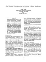
Figure 1.1 Schematic presentation of different types of magnetic nanostructured
materials. ( Leslie-Pelecky and Rieke 1996 ).
The classification is illustrated in Figure 1.1 [18]. Type A is denoted for
systems consisting isolated particles with nanoscale diameters. Since the
interparticle interactions can be ignored for these systems, their unique magnetic
properties are completely attributable to the isolated components with
their
reduced sizes. Another type, type D, is assigned to bulk materials with
nanoscale structure. This type is featured by a significant fraction ( up to 50 % )
of the sample volume composed of grain bound-aries and interfaces. Compared
9
with type A systems, the interparticle interactions cannot be ignored and the bulk
magnetic properties for type D are indeed dominated by the interactions. It is
believed that the length scale of the interactions can span up to many grains and is
critically related to the interphase characteristics. Because of the existence of the
interactions and grain boundaries, the magnetic behaviors of type D nanostructures
cannot be predicted theoretically simply by considering only the polycrystalline
materials with reduced length scales. Other than type A and type D, intermediate
forms such as core– shell nanoparticles (type B) and nanoparticle-based
nanocomposites (type C) are classified, as shown in Figure 1.1. In type B, the shells
on magnetic nanoparticles, which may not be magnetic themselves, are usually used
to reduce interparticle interactions. For type C systems, the magnetic properties of
nano composites are determined by the faction of magnetic nanoparticles as well as
the characteristics of the matrix material [18].
1.2. Single-domain particles
Single-domainand multidomain are important for ultrafine magnetic
particles. Domain walls have a characteristic width and energy associated with
their formation and existence. They separate domains – groups of spins all pointing
in the same direction
and
acting cooperatively. Reversing magnetization is
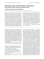
primarily achieved by the motion of domain walls. Figure 1.2 illustrates the
dependence of coercivity on particle size by an experimental investigation.
Multidomain is the case for large particles in which domain walls form energyfavorably. As the particle size decreases below a critical diameter D c, single-domain
particles form where the formation of domain walls becomes energetically
unfavorable. Thus, magnetization reversal cannot be obtained readily leading to
larger coercivities because of the lack of nucleation and motion of the domain
walls. If the particle size continues to decrease, the spins are increasingly
influenced
by
thermal
fluctuations
and
this
phenomenon
is
called
superparamagnetism. The estimated single-domain diameter for some materials in
the shape of spherical particles is listed [7].
10
Figure 1.2 Qualitative illustration of the coercivity behavior in the function of
particle sizes in particle systems. Adapted from Leslie-Pelecky, D.L. and Rieke, R.D.
(1996). Magnetic Properties of Nanostructured Materials, Chemistry of Materials,
8(8), 1770 – 83.
Table 1. Estimated values of single-domain sizes forspherical nanoparticles
without shape anisotropy. Reproduced by permission of American Chemical
Society. Adapted from Leslie-Pelecky, D.L and Rieke.
Material
Dcrit (nm)
Material
Dcrit (nm)
Co
70
Fe304
128
Fe
14
γ- Fe203
166
Ni
55
1.3. Superparamagnetism
It has been shown theoretically that, for very small magnetic particles, as the
thermal fluctuation can prevent the existence of a stable magnetization, coercivity
Hc approaches zero. This superparamagnetism has two experimental criteria
which are no hysteresis for the magnetization curve and overlapping of the
magnetization curves at different temperatures. Possible reasons for imperfect
superposition could be anisotropy effects, a wide distribution of particle sizes,
11
and changes of spontaneous particle magnetization with temperatures. The width
and mean particle size of superparamagnetic particles can be obtained by
determining the magnetization as a function of field. It is necessary to point out that
this method can only be used for weakly interacting systems where the interparticle
interactions are not considered [18].
1.4. Size dependence of the magnetic properties of nanoparticles
Some studies found that the size-dependent effect of saturation
magnetization is attributable to the decrease of cohesive energy [7,14]. Generally,
the size-dependent cohesive energy En of spherical nanoparticles can be described
as
(1.1)
where Svib denotes the vibrational part of the overall melting entropy S m, R is the
idealgas constant, and h denotes the atomic diameter. By incorporating the bond
order-length-strength (BOLS) correlation mechanism into the Ising convention and
the Brillouin function, a simplified model can be developed to describe the
relationship between the saturation magnetization MSn of spherical nanoparticles
and the average size D of nanoparticles:
(1.2)
With increasing particle sizes, the magnetization of the samples increases
with applied field. The Ms ,Mr , and Hc of spherical Ni nanoparticles are sizedependent. More specifically, the Ms and Mr increase and the Hc decreases
monotonously with increasing D, indicating a distinct size effect. According to the
effect of particle size on the magnetic coercivity, the H c of the multidomain
ferromagnetic nanoparticles conforms to the rule as shown in the following
equation:
(1.3)
By means of thermal decomposition, He et al. prepared single-phase
spherical Ni nanoparticles (23 to 114 nm in diameter) that are face-centered cubic
in structure. Their measurement of magnetic hysteresis loop reveals that the
12
saturation magnetization MS and remanent magnetization increase and the
coercivity decreases monotonously with increasing particle size, indicating a
distinct size effect. They also found that with increase of surface-to-volume ratio of
Ni nanoparticles due to decrease of particle size, there is increase of the percentage
of magnetically inactive layer [14].
1.5. Introduction of soft magnetic materials
Soft magnetic materials are those materials that are easily magnetized and
demagnetized. They typically have intrinsic coercivity less than 1000 Am -1. They
are used primarily to enhance and/or channel the flux produced by an electric
current. The main parameter, often used as a figure of merit for soft magnetic
materials, is the relative permeability (Mr, where Mr= B/MoH), which is measure of
how readily the material responds to the applied magnetic field.
Magnetically soft materials with high performances at high frequencies are
one of the key materials for the recent development of high density electronic
circuits and increase of operation frequencies up to a few GHz. They are useful as
magnetic cores in downsized inductors and DC–DC converters, and also as
electromagnetic noise absorbers to avoid malfunction of electronic circuits. All of
these applications have been calling for magnetically soft materials with high
saturation magnetization (Ms), high permeability and, in many cases, low energy
loss [14].
For
biomedical
uses,
the
application
of
particles
that
present
superparamagnetic behavior at room temperature is preferred. Furthermore,
applications intherapy and biology and medical diagnosis require the magnetic
particles to be stablein water at pH 7 and in a physiological environment. The
colloidal stability of this fluid will depend on the charge and surface chemistry,
which give rise to both stericand coulombic repulsions and also depend on the
dimensions of the particles, which should be sufficiently small so that precipitation
due to gravitation forces can be avoided. Additional restrictions to the possible
particles could be used for biomedical applications (in vivo orin vitro applications).
13
Forin vivo applications, the magnetic nanoparticles must be encapsulated with a
biocompatible polymerduring or after the preparation process to prevent changes
from the original structure, the formation of large aggregates, and biodegradation
when exposed to thebiological system. The nanoparticle coated with polymer will
also allow binding ofdrugs by entrapment on the particles, adsorption, or covalent
attachment. The major factors, which determine toxicity and the biocompatibility of
these materials, are the nature of the magnetically responsive components, such
asmagnetite, iron, nickel, and cobalt, and the final size of the particles, their core,
andthe coatings. Iron oxide nanoparticles such as magnetite (Fe 3O4) or its oxidized
formmaghemite (γ-Fe2O3) are by far the most commonly employed nanoparticles
forbiomedical applications. Highly magnetic materials such as cobalt and nickel
aresusceptible to oxidation and are toxic; hence, they are of little interest. Moreover,
the major advantage of using particles of sizes smaller than 100 nm is their higher
effective surface areas, lower sedimentation rates, and improved tissular diffusion.
Another advantage of using nanoparticles is that the magnetic dipole-dipole
interactions are significantly reduced because they scale as r 6 (r is the particle
radius) [14]. Therefore, forin vivo biomedical applications, magnetic nanoparticles
must be madeof a non-toxic and non-immunogenic material, with particle sizes
small enough toremain in the circulation after injection and to pass through the
capillary systems oforgans and tissues, avoiding vessel embolism. They must also
have a high magnetization so that their movement in the blood can be controlled
with a magneticfield and so that they can be immobilized close to the targeted
pathologic
tissue.
Forin
vitro
applications,
composites
consisting
of
superparamagnetic nano crystals dispersed in submicron diamagnetic particles with
one sedimentationtimes in the absence of a magnetic field can be used because the
size restrictions arenot so severe as inin vivo applications. The major advantage of
sing diamagnetic matrixes is that the superparamagnetic composites can be easily
prepared with functionality [14].
14
1.6. Introduction of NiFe magnetic materials
Ni-Fe alloys exhibit good soft magnetic properties such as low coercivity and
high permeability and have been applied in a range of electric devices for the
purpose of shielding and converging magnetic flux. Both the magneto crystalline
anisotropy and magnetostriction constants become nearly zero at an alloy
composition of Fe22Ni78 and thus, this alloy is well-known for its excellent soft
magnetic properties [12].
Permalloy is a nickel–iron magnetic alloy, which are extremely versatile and
are used over a wide range of compositions, from 30 to 80 % Ni. Over this
composition range the properties vary and the optimum composition must be
selected for a particular application. The high Ni content alloys have high
permeability; around 50 % Ni has high saturation magnetization and low Ni content
have a high electrical resistance [14].
Permalloy (79 % Ni and 21 % Fe) are intensively used in MEMS devices,
such as μ-relays, μ-switches, μ-pumps and μ-motors. In electromagnetic devices
,
the attainable energy density is limited by the saturation flux density (B s) of the soft
magnetic material used [14].
NiFe nano-material exists in various forms such as: thin film, nanowire,
nanotube and nanoparticle, which can be synthesized by a number of physical or
chemical methods, one of them is electrodeposition method that is low-cost and
effective. There are several types of electrodeposition method as shown in Table 2
Table 2.Types of nanostructured materials which may be produced by
electrodeposition techniques
Types of nanostructure materials
Method of
electrodeposition
Nanoparticles in a
Nanomultimetal deposit
layers
Direct current
(DC)
15
Nanotubes/
nanowires
Nanocrytalline
materials
Pulsed direct
current (PDC)
Pulsed reverse
current (PRC)
Potentiostatic (P)
Pulsed
potentiostatic (PP)
For many advantage properties, a large number of studies have been carried
out on electrodeposited NiFe materials. Liang et al. has found that FeNi thin film
deposited with Mo or Al yields magnetically soft materials and that depositing with
B further increases the softness.The out-of-plane magnetic anisotropy of FeNi thin
films is reduced by depositing with Al and completely removed by depositing with
B. The effect of depositing with Mo isdependent on the Mo concentration. The
coercivity of FeNiMo and FeNiAl is reduced toless than a half of that of FeNi, and
a value as low as 40 A/m is obtained for FeNiB [14].
Shimada et al. proposed a high permeability material composed of micronsize Fe particles and nanometer-size particles with magnetic softness. The optimum
volume density of ferromagnetic NPs is an important factor to improve permeability
of the composites and their main study was on this subject. However, the optimum
conditions of many other factors such as NP size and its distribution, dispersion of
the NPs in Fe particle matrix and organic solvents, etc. are yet unknown.Qin et
al.fabricated Ni80Fe20 NPs with various monodispersed sizes prepared by a polyol
method to investigate their basic properties with magnetic softness [3].
Therefore, to evaluate and compare the results of these studies, this work
concentrated on investigation soft magnetic properties of NiFe nanoparticles .
1.7 Magnetism of Magnetic Nanorods
Due to their quasi one-dimensional structure, magnetic nanorods exhibit
unique magnetic properties. The magnetic properties of a nanorods are related to
many parameters of the nanorods, such as composition, length and diameter. For a
16
multi-segment nanorods, its magnetic properties are also related to the layer
thickness and the spacing between layers. Besides, the low dimensionality of
nanorods brings about fundamental magnetic anisotropy. Some magnetic properties
of magnetic nanorods, such as coercivity, remanence, saturation magnetic field and
saturate magnetization, are dependent on the direction of the externally applied
magnetic field. The giant magnetoresistance of a multilayer nanorods is caused by
the segmented structure of the nanorods [14].
1.8 Shape Anisotropy
When a magnetic field is applied to a spherical object, the orientation of the
magnetic field does not affect the magnetization of the spherical object. However,
the magnetization of a non-spherical object depends on the orientation of the
magnetic field. It is easier to magnetize a non-sphericalobject when the magnetic
field is applied along the long axis of the object than along its short axis. For an
object under an external magnetic field, the magnetic field inside the object is
usually called the demagnetizing field, as this field tends to demagnetize the
material. The demagnetizing field, Hd, is proportional to the magnetization M that
creates it, but in an opposite direction, as given by:
Hd = −NdM
(2.1)
where the demagnetizing factor Nd is related to the shape of the object. Because the
calculation is quite complicated, the exact value N d can be calculated only for an
ellipsoidal object with uniform magnetization all over the object. To an ellipsoidal
object with semi-axes a, b and c (c ≥ b ≥ a), the sum of demagnetization factors
along the three semi-axes ( Na, Nb and Nc) equals to 4π.
Na+ Nb+ Nc= 4π
(2.2)
For a given magnetization direction, the magnetostatic energy E D (erg/cm3) is
given by:
ED = Nd Ms2
(2.3)
where Ms (emu/cm3) is the saturate magnetization of the object, and N d is the
demagnetization factor for the magnetization direction [14].
1.9 Magnetization Hysteresis Loops
17
The magnetization hysteresis loop of a sample illustrates how this sample
responds to an external magnetic field, and theoretically, the magnetization
hysteresis loop of an arbitrary sample can be obtained by minimizing the total free
energy of the object in an external magnetic field. The hysteresis loop of an object is
affected by many factors, such as material, microstructure, shape, size of the object,
the orientation of the magnetizing field, and the magnetization history of the
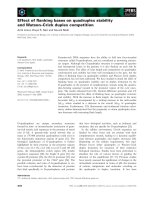
sample. Figure 1.3 schematically shows two typical magnetization hysteresis loops
for an array of Ni nanorods.
Figure 1.3: Hysteresis loops for a nickel nanorods array. The diameter of
the nanorods is 100 nm, and their length is 1 µm. (a) The applied magnetic field H
is parallel to the axis of the nanorods; (b) the applied field H is perpendicular to the
axis of the nanorods.
The parameters are often used in describing the characteristics of a sample
include the saturate magnetization Ms, the remanent magnetization Mr, the
saturation field Hsat and the coercivity Hc. As shown in Figure 1.3, the saturation
field Hsat is the field required for the sample to achieve the saturate magnetization
Ms; the remanent magnetization Mr is the magnetization of the sample when the
external magnetic field is moved away; the coercivity H c is the magnetic field
corresponding to the zero magnetization. There is another important parameter,
switching field Hs, which is often used in analyzing magnetic nanomaterial. It is
defined as the field at which the slope of the M–H loop reaches its maximum value.
Actually, it is the field required to switch the magnetization from one direction to
the opposite direction. Usually, the switching field Hs is equal to the coercivity Hc.
The saturate magnetization Ms of an object is achieved when all the magnetic
moments in the object are aligned in the same direction. Therefore, the saturate
18
magnetization Ms is an intrinsic property of a magnetic material, which is not
related to thesize and shape of the sample
The magnetic behaviors of a nanorods array are mainly determined by two
parameters including magnetic properties of the individual nanorods, and
interactions among the individual magnetic nanorods, which are related to the
geometry parameters of the nanorods array. [14]
2. CHAPTER 2: EXPERIMENT METHODS
2.1. Electrodeposition
There are several techniques such as VLS (Vapor Liquid Solid method),
CVD (Chemical Vapor Deposition) and template assisted synthesis are developed
for the synthesis of nanowires [19, 14]. Among them template assisted
electrochemical synthesis is facile, cost effective, as it can be used for producing
large quantities of nanorods with desired features like aspect ratio, composition and
size [16]. In addition, this method allows the fabrication of single-segment and
multi-segment nanorods. Using this technique, different segments can be introduced
along the axis of a nanorods, and it is particularly attractive for the realization of
multi-functionality. Furthermore, the materials for individual segments may be
metals, alloys, metal oxides or electronically conducting polymers, and so specific
magnetic, optical or electrical properties can be achieved [11].
In 1996, Martin [6] first employed this technique in synthesizing metallic
nanowires using polycarbonate membrane as template. Subsequently, the
electrochemical deposition has been used extensively in fabricating single metallic
nanorods and multilayered metallic nanorods (super-lattice) with controlled
thickness for magnetic property studies [19, 7]. Electrodeposition is a process in
which an electrical current passes through an electrolyte of metallic ions, and a
reduction takes place when the ion encounters the cathode (working electrode) [2].
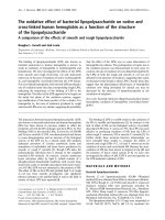
In the electrodeposition using a nanoporous membrane as a structure to create
nanorods arrays, electrodeposition takes place in the channels of the membrane. As
shown in figure 2.1, electrodeposition of nanowires is usually done in a threeelectrode arrangement, consisting of a reference electrode, a specially designed
19
cathode and an anode or counter electrode. Usually the applied substrate will be
served as the working electrode and several inert metals will be served as counter
electrode and reference electrode, such as Pt wire. The standard Ag/AgCl is also the
often-used reference electrode.
Initially, Anodized Alumina Membrane (AAM) and ion track-etched polymer
membrane were developed for lab filtration applications. These two types of
membrane occupy relatively precise pore structure and narrow pore size
distribution, which is suitable for filtrate certain sized material and biological
particles.
Figure 2.1 Three-electrode arrangement for electrodeposition of nanorods
In comparison to nanorods electrochemically synthesized using commercial
AAM as template, the nanorods fabricated electrochemically based on track-etched
polycarbonate membranes have much better diameter uniformity, smooth surface
and cheap. The drawback is that the nanorods density is low (membrane pore
density around 109 / ) and the distribution is not uniform, which could affect the
subsequent magnetic property measurements due to the different interactions among
vicinal individual nanorods [1].
2.2 Sonoelectrodeposition system
20
There are many ways to create NiFe-nanostructured materials including
physical techniques such as mechanical deformation, arcmelting, vacuum
evaporation (sputtering and thermal evaporation), laser ablation pulse, chemical
methods, and physicochemical method such as electrodeposition. Up to now, the
vacuum evaporation is the most used method. Electrodeposition is a promising way
to obtain nanorods or thin film because it is less expensive than physical methods,
less complicated than chemical methods. But by this technique, it is difficult to get
nanoparticles with large quantity. Sonoelectrochemistry was developed to make
nanoparticles. It combined the advantages of sonochemistry and electrodeposition.
Sonochemistry is a very useful synthetic method which was discovered as early as
1934 that the application of ultrasonic energy could increase the rate of electrolytic
water cleavage. The effects of ultrasonic radiation on chemical reactions are due to
the very high temperatures and pressures, which develop in and around the
collapsing bubble. Sonoelectrochemistry has the potential benefit of combining
sonochemistry with electrochemistry. Some of these beneficial effects include
acceleration of mass transport, cleaning and degassing of the electrode surface, and
an increased reaction rate [14].
Figure 2.2 Controller system.
21
Figure 2.3 Sonoelectrode system.
The sonoelectrodeposition system has a controller system in Figure 2.2(PC,
sonochemical-potentiostat controller), a sonotrode in Figure 2., a platinum
substrate.
The bath composition and fabricating conditions are given in Table 3
Table 3 Electrolyte composition and operating conditions
Nickel chloride (g/L)
1.29
Iron chloride (g/L)
1.26
Temperature (K)
325 – 327
Time current on (s)
0.2
Time off (s)
0.5
Time ultrasound on (s)
0.3
Duration (s)
1800
Frequency (kHz)
12
Cathodic overpotential (V)
3–8
Sonoelectrodeposition was conducted at CMS, VNU University of Science.
22
2.2. Cyclic voltametary (CV)
Cyclic voltammetry (CV) is one type of potentiodynamic electrochemical
measurements. Generally speaking, the operating process is a potential-controlled
reversible experiment, which scans the electric potential before turning to reverse
direction after reaching the final potential and then scans back to the initial
potential. When voltage is applied to the system changes with time, the current will
change with time accordingly as shown in Figure 2. b.
Thus the curve of current and voltage, can be represented from the data,
which can be obtained from Figure 2. a and b
23
Figure 2.4 Potential wave changes with time (a); current response with time
(b); current-potential representations (c). Adapted from D. K. Gosser, Jr. Cyclic
Voltammetry Simulation and Analysis of Reaction Mechanisms, Wiley-VCH, New
York, (1993).
24
Figure 2.5 Components of cyclic voltammetry systems. Adapted from D. K.
Gosser, Jr., Cyclic Voltammetry Simulation and Analysis of Reaction Mechanisms,
Wiley-VCH, NewYork, (1993).
Cyclic voltammetry systems employ different types of potential waveforms
(Figure 2.) that can be used tosatisfy different requirements. Potential waveforms
react the way potential is applied to this system. These different types are referred to
by characteristic names, for example, cyclic voltammetry, and differential pulse
voltammetry. The cyclic voltammetry analytical method is the one whose potential
waveform is generallyan isosceles triangle ( Figure 2.a ) [2].
25