M11 YOUN7066 13 ISM c11 kho tài liệu bách khoa
Bạn đang xem bản rút gọn của tài liệu. Xem và tải ngay bản đầy đủ của tài liệu tại đây (921.35 KB, 44 trang )
EQUILIBRIUM AND ELASTICITY
11.1.
11
IDENTIFY: Use Eq. (11.3) to calculate xcm . The center of gravity of the bar is at its center and it can be
treated as a point mass at that point.
SET UP: Use coordinates with the origin at the left end of the bar and the + x axis along the bar.
m1 = 0.120 kg, m2 = 0.055 kg, m3 = 0.110 kg.
EXECUTE:
11.2.
m1x1 + m2 x2 + m3 x3 (0.120 kg)(0.250 m) + 0 + (0.110 kg)(0.500 m)
=
= 0.298 m. The
0.120 kg + 0.055 kg + 0.110 kg
m1 + m2 + m3
fulcrum should be placed 29.8 cm to the right of the left-hand end.
EVALUATE: The mass at the right-hand end is greater than the mass at the left-hand end. So the center of
gravity is to the right of the center of the bar.
IDENTIFY: Use Eq. (11.3) to calculate xcm of the composite object.
SET UP: Use coordinates where the origin is at the original center of gravity of the object and + x is to the
right. With the 1.50 g mass added, xcm = −2.20 cm, m1 = 5.00 g and m2 = 1.50 g. x1 = 0.
⎛ m + m2 ⎞
⎛ 5.00 g + 1.50 g ⎞
m2 x2
. x2 = ⎜ 1
⎟ xcm = ⎜
⎟ (−2.20 cm) = −9.53 cm.
1.50 g
m1 + m2
⎝
⎠
⎝ m2 ⎠
The additional mass should be attached 9.53 cm to the left of the original center of gravity.
EVALUATE: The new center of gravity is somewhere between the added mass and the original center of
gravity.
IDENTIFY: Treat the rod and clamp as point masses. The center of gravity of the rod is at its midpoint, and
we know the location of the center of gravity of the rod-clamp system.
m x + m2 x2
SET UP: xcm = 1 1
.
m1 + m2
EXECUTE:
11.3.
xcm =
xcm =
EXECUTE: 1.20 m =
(1.80 kg)(1.00 m) + (2.40 kg) x2
.
1.80 kg + 2.40 kg
(1.20 m)(1.80 kg + 2.40 kg) − (1.80 kg)(1.00 m)
= 1.35 m
2.40 kg
EVALUATE: The clamp is to the right of the center of gravity of the system, so the center of gravity of the
system lies between that of the rod and the clamp, which is reasonable.
IDENTIFY: Apply the first and second conditions for equilibrium to the trap door.
SET UP: For ∑ τ z = 0 take the axis at the hinge. Then the torque due to the applied force must balance the
x2 =
11.4.
torque due to the weight of the door.
EXECUTE: (a) The force is applied at the center of gravity, so the applied force must have the same
magnitude as the weight of the door, or 300 N. In this case the hinge exerts no force.
(b) With respect to the hinges, the moment arm of the applied force is twice the distance to the center of
mass, so the force has half the magnitude of the weight, or 150 N.
The hinges supply an upward force of 300 N − 150 N = 150 N.
EVALUATE: Less force must be applied when it is applied farther from the hinges.
© Copyright 2012 Pearson Education, Inc. All rights reserved. This material is protected under all copyright laws as they currently exist.
No portion of this material may be reproduced, in any form or by any means, without permission in writing from the publisher.
11-1
11-2
11.5.
Chapter 11
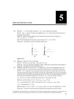
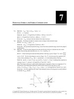
IDENTIFY: Apply ∑τ z = 0 to the ladder.
SET UP: Take the axis to be at point A. The free-body diagram for the ladder is given in Figure 11.5. The
torque due to F must balance the torque due to the weight of the ladder.
EXECUTE: F (8.0 m)sin 40° = (2800 N)(10.0 m), so F = 5.45 kN.
EVALUATE: The force required is greater than the weight of the ladder, because the moment arm for F is
less than the moment arm for w.
Figure 11.5
11.6.
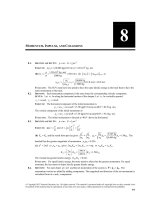
IDENTIFY: Apply the first and second conditions of equilibrium to the board.
SET UP: The free-body diagram for the board is given in Figure 11.6. Since the board is uniform its center
of gravity is 1.50 m from each end. Apply ∑ Fy = 0, with + y upward. Apply ∑τ z = 0 with the axis at the
end where the first person applies a force and with counterclockwise torques positive.
EXECUTE: ∑ Fy = 0 gives F1 + F2 − w = 0 and F2 = w − F1 = 160 N − 60 N = 100 N. ∑ τ z = 0 gives
⎛ w⎞
⎛ 160 N ⎞
F2 x − w(1.50 m) = 0 and x = ⎜ ⎟ (1.50 m) = ⎜
⎟ (1.50 m) = 2.40 m. The other person lifts with a
⎝ 100 N ⎠
⎝ F2 ⎠
force of 100 N at a point 2.40 m from the end where the other person lifts.
EVALUATE: By considering the axis at the center of gravity we can see that a larger force is applied by
the person who pushes closer to the center of gravity.
Figure 11.6
11.7.
IDENTIFY: Apply ∑ Fy = 0 and ∑τ z = 0 to the board.
SET UP: Let + y be upward. Let x be the distance of the center of gravity of the motor from the end of the
board where the 400 N force is applied.
EXECUTE: (a) If the board is taken to be massless, the weight of the motor is the sum of the applied
(2.00 m)(600 N)
= 1.20 m from the end where the 400 N force is
forces, 1000 N. The motor is a distance
(1000 N)
applied, and so is 0.800 m from the end where the 600 N force is applied.
(b) The weight of the motor is 400 N + 600 N − 200 N = 800 N. Applying ∑τ z = 0 with the axis at the
end of the board where the 400 N acts gives (600 N)(2.00 m) = (200 N)(1.00 m) + (800 N)x and
x = 1.25 m. The center of gravity of the motor is 0.75 m from the end of the board where the 600 N force
is applied.
EVALUATE: The motor is closest to the end of the board where the larger force is applied.
© Copyright 2012 Pearson Education, Inc. All rights reserved. This material is protected under all copyright laws as they currently exist.
No portion of this material may be reproduced, in any form or by any means, without permission in writing from the publisher.
Equilibrium and Elasticity
11.8.
11-3
IDENTIFY: Apply the first and second conditions of equilibrium to the shelf.
SET UP: The free-body diagram for the shelf is given in Figure 11.8. Take the axis at the left-hand end of the
shelf and let counterclockwise torque be positive. The center of gravity of the uniform shelf is at its center.
EXECUTE: (a) ∑τ z = 0 gives − wt (0.200 m) − ws (0.300 m) + T2 (0.400 m) = 0.
(25.0 N)(0.200 m) + (50.0 N)(0.300 m)
= 50.0 N
0.400 m
∑ Fy = 0 gives T1 + T2 − wt − ws = 0 and T1 = 25.0 N. The tension in the left-hand wire is 25.0 N and the
T2 =
tension in the right-hand wire is 50.0 N.
EVALUATE: We can verify that ∑τ z = 0 is zero for any axis, for example for an axis at the right-hand end
of the shelf.
Figure 11.8
11.9.
IDENTIFY: Apply the conditions for equilibrium to the bar. Set each tension equal to its maximum value.
SET UP: Let cable A be at the left-hand end. Take the axis to be at the left-hand end of the bar and x be the
distance of the weight w from this end. The free-body diagram for the bar is given in Figure 11.9.
EXECUTE: (a) ∑ Fy = 0 gives TA + TB − w − wbar = 0 and
w = TA + TB − wbar = 500.0 N + 400.0 N − 350.0 N = 550 N.
(b) ∑τ z = 0 gives TB (1.50 m) − wx − wbar (0.750 m) = 0.
TB (1.50 m) − wbar (0.750 m) (400.0 N)(1.50 m) − (350 N)(0.750 m)
=
= 0.614 m. The weight should
w
550 N
be placed 0.614 m from the left-hand end of the bar (cable A).
EVALUATE: If the weight is moved to the left, TA exceeds 500.0 N and if it is moved to the right
x=
TB exceeds 400.0 N.
Figure 11.9
© Copyright 2012 Pearson Education, Inc. All rights reserved. This material is protected under all copyright laws as they currently exist.
No portion of this material may be reproduced, in any form or by any means, without permission in writing from the publisher.
11-4
Chapter 11
11.10.
IDENTIFY: Apply the first and second conditions for equilibrium to the ladder.
SET UP: Let n2 be the upward normal force exerted by the ground and let n1 be the horizontal normal
force exerted by the wall. The maximum possible static friction force that can be exerted by the ground
is μs n2 .
EXECUTE: (a) Since the wall is frictionless, the only vertical forces are the weights of the man and the
ladder, and the normal force n2 . For the vertical forces to balance, n2 = w1 + wm = 160 N + 740 N = 900 N,
and the maximum frictional force is μs n2 = (0.40)(900N) = 360 N.
(b) Note that the ladder makes contact with the wall at a height of 4.0 m above the ground. Balancing
torques about the point of contact with the ground,
(4.0 m)n1 = (1.5 m)(160 N) + (1.0 m)(3/5)(740 N) = 684 N ⋅ m, so n1 = 171.0 N. This horizontal force
must be balanced by the friction force, which must then be 170 N to two figures.
(c) Setting the friction force, and hence n1, equal to the maximum of 360 N and solving for the distance x
along the ladder, (4.0 m)(360 N) = (1.50 m)(160 N) + x(3/5)(740 N), so x = 2.7 m.
11.11.
EVALUATE: The normal force exerted by the ground doesn’t change as the man climbs up the ladder. But
the normal force exerted by the wall and the friction force exerted by the ground both increase as he moves
up the ladder.
IDENTIFY: The system of the person and diving board is at rest so the two conditions of equilibrium
apply.
(a) SET UP: The free-body diagram for the diving board is given in Figure 11.11. Take the origin of
coordinates at the left-hand end of the board (point A).
G
F1 is the force applied at the support
G
point and F2 is the force at the end
that is held down.
Figure 11.11
EXECUTE: ∑τ A = 0 gives + F1(1.0 m) − (500 N)(3.00 m) − (280 N)(1.50 m) = 0
(500 N)(3.00 m) + (280 N)(1.50 m)
= 1920 N
1.00 m
(b) ∑ Fy = ma y
F1 =
F1 − F2 − 280 N − 500 N = 0
F2 = F1 − 280 N − 500 N = 1920 N − 280 N − 500 N = 1140 N
EVALUATE: We can check our answers by calculating the net torque about some point and checking that
∑τ z = 0 for that point also. Net torque about the right-hand end of the board:
(1140 N)(3.00 m) + (280 N)(1.50 m) − (1920 N)(2.00 m) = 3420 N ⋅ m + 420 N ⋅ m − 3840 N ⋅ m = 0, which
11.12.
checks.
IDENTIFY: Apply the first and second conditions of equilibrium to the beam.
SET UP: The boy exerts a downward force on the beam that is equal to his weight.
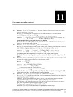
EXECUTE: (a) The graphs are given in Figure 11.12.
(b) x = 6.25 m when FA = 0, which is 1.25 m beyond point B.
(c) Take torques about the right end. When the beam is just balanced, FA = 0, so FB = 900 N.
The distance that point B must be from the right end is then
(300 N)(4.50 m)
= 1.50 m.
(900 N)
© Copyright 2012 Pearson Education, Inc. All rights reserved. This material is protected under all copyright laws as they currently exist.
No portion of this material may be reproduced, in any form or by any means, without permission in writing from the publisher.
Equilibrium and Elasticity
11-5
EVALUATE: When the beam is on the verge of tipping it starts to lift off the support A and the normal
force FA exerted by the support goes to zero.
Figure 11.12
11.13.
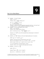
IDENTIFY: Apply the first and second conditions of equilibrium to the strut.
(a) SET UP: The free-body diagram for the strut is given in Figure 11.13a. Take the origin of coordinates
at the hinge (point A) and + y upward. Let Fh and Fv be the horizontal and vertical components of the
G
force F exerted on the strut by the pivot. The tension in the vertical cable is the weight w of the
suspended object. The weight w of the strut can be taken to act at the center of the strut. Let L be the length
of the strut.
EXECUTE:
∑ Fy = ma y
Fv − w − w = 0
Fv = 2 w
Figure 11.13a
Sum torques about point A. The pivot force has zero moment arm for this axis and so doesn’t enter into the
torque equation.
τA = 0
TL sin 30.0° − w(( L/2)cos30.0°) − w( L cos30.0°) = 0
T sin 30.0° − (3w/2)cos30.0° = 0
© Copyright 2012 Pearson Education, Inc. All rights reserved. This material is protected under all copyright laws as they currently exist.
No portion of this material may be reproduced, in any form or by any means, without permission in writing from the publisher.
11-6
Chapter 11
3w cos30.0°
= 2.60 w
2sin 30.0°
Then ∑ Fx = ma x implies T − Fh = 0 and Fh = 2.60 w.
G
We now have the components of F so can find its magnitude and direction (Figure 11.13b).
T=
F = Fh2 + Fv2
F = (2.60 w) 2 + (2.00 w) 2
F = 3.28w
F
2.00 w
tan θ = v =
Fh 2.60 w
θ = 37.6°
Figure 11.13b
(b) SET UP: The free-body diagram for the strut is given in Figure 11.13c.
Figure 11.13c
The tension T has been replaced by its x and y components. The torque due to T equals the sum of the
torques of its components, and the latter are easier to calculate.
EXECUTE: ∑ τ A = 0 + (T cos30.0°)( L sin 45.0°) − (T sin 30.0°)( L cos 45.0°) −
w(( L/2)cos 45.0°) − w( L cos 45.0°) = 0
The length L divides out of the equation. The equation can also be simplified by noting that
sin 45.0° = cos 45.0°.
Then T (cos30.0° − sin 30.0°) = 3w/2.
T=
3w
= 4.10w
2(cos30.0° − sin 30.0°)
∑ Fx = max
Fh − T cos30.0° = 0
Fh = T cos30.0° = (4.10w)(cos30.0°) = 3.55w
∑ Fy = ma y
Fv − w − w − T sin 30.0° = 0
Fv = 2 w + (4.10 w)sin 30.0° = 4.05w
© Copyright 2012 Pearson Education, Inc. All rights reserved. This material is protected under all copyright laws as they currently exist.
No portion of this material may be reproduced, in any form or by any means, without permission in writing from the publisher.
Equilibrium and Elasticity
11-7
From Figure 11.13d,
F = Fh2 + Fv2
F = (3.55w) 2 + (4.05w)2 = 5.39 w
Fv 4.05w
=
Fh 3.55w
θ = 48.8°
tan θ =
Figure 11.13d
11.14.
EVALUATE: In each case the force exerted by the pivot does not act along the strut. Consider the net
torque about the upper end of the strut. If the pivot force acted along the strut, it would have zero torque
about this point. The two forces acting at this point also have zero torque and there would be one nonzero
torque, due to the weight of the strut. The net torque about this point would then not be zero, violating the
second condition of equilibrium.
IDENTIFY: Apply the first and second conditions of equilibrium to the beam.
SET UP: The free-body diagram for the beam is given in Figure 11.14. H v and H h are the vertical and
horizontal components of the force exerted on the beam at the wall (by the hinge). Since the beam is
uniform, its center of gravity is 2.00 m from each end. The angle θ has cosθ = 0.800 and sin θ = 0.600.
The tension T has been replaced by its x and y components.
EXECUTE: (a) H v , H h and Tx = T cosθ all produce zero torque. ∑τ z = 0 gives
− w(2.00 m) − wload (4.00 m) + T sin θ (4.00 m) = 0 and T =
(150 N)(2.00 m) + (300 N)(4.00 m)
= 625 N.
(4.00 m)(0.600)
(b) ∑ Fx = 0 gives H h − T cos θ = 0 and H h = (625 N)(0.800) = 500 N. ∑ Fy = 0 gives
H v − w − wload + T sin θ = 0 and H v = w + wload − T sin θ = 150 N + 300 N − (625 N)(0.600) = 75 N.
EVALUATE: For an axis at the right-hand end of the beam, only w and H v produce torque. The torque due
to w is counterclockwise so the torque due to H v must be clockwise. To produce a clockwise torque,
H v must be upward, in agreement with our result from ∑ Fy = 0.
Figure 11.14
11.15.
IDENTIFY: The athlete is in equilibrium, so the forces and torques on him must balance. The target
variables are the forces on his hands and feet due to the floor.
SET UP: The free-body diagram is given in Figure 11.15. Ff is the force on each foot and Fh is the force
on each hand. Use coordinates as shown. Take the pivot at his feet and let counterclockwise torques be
positive. ∑τ z = 0 and ∑ Fy = 0.
© Copyright 2012 Pearson Education, Inc. All rights reserved. This material is protected under all copyright laws as they currently exist.
No portion of this material may be reproduced, in any form or by any means, without permission in writing from the publisher.
11-8
Chapter 11
Figure 11.15
EXECUTE: ∑τ z = 0 gives (2 Fh )(1.70 m) − w(1.15 m) = 0. Solving for Fh gives
Fh = w
1.15 m
= 0.338w = 272 N. Applying ∑ Fy = 0, we get 2 Ff + 2 Fh − w = 0 which gives
2(1.70 m)
Ff = 12 w − Fh = 402 N − 272 N = 130 N.
11.16.
EVALUATE: His center of mass is closer to his hands than to his feet, so his hands exert a greater force.
IDENTIFY: Apply the conditions of equilibrium to the wheelbarrow plus its contents. The upward force
applied by the person is 650 N.
SET UP: The free-body diagram for the wheelbarrow is given in Figure 11.16. F = 650 N,
wwb = 80.0 N and w is the weight of the load placed in the wheelbarrow.
EXECUTE: (a) ∑τ z = 0 with the axis at the center of gravity gives n (0.50 m) − F (0.90 m) = 0 and
⎛ 0.90 m ⎞
n = F⎜
⎟ = 1170 N. ∑ Fy = 0 gives F + n − wwb − w = 0 and
⎝ 0.50 m ⎠
w = F + n − wwb = 650 N + 1170 N − 80.0 N = 1740 N.
(b) The extra force is applied by the ground pushing up on the wheel.
EVALUATE: You can verify that ∑τ z = 0 for any axis, for example for an axis where the wheel contacts
the ground.
Figure 11.6
11.17.
IDENTIFY: Apply the first and second conditions of equilibrium to Clea.
SET UP: Consider the forces on Clea. The free-body diagram is given in Figure 11.17
EXECUTE:
nr = 89 N, nf = 157 N
nr + nf = w so w = 246 N
Figure 11.17
© Copyright 2012 Pearson Education, Inc. All rights reserved. This material is protected under all copyright laws as they currently exist.
No portion of this material may be reproduced, in any form or by any means, without permission in writing from the publisher.
Equilibrium and Elasticity
11-9
∑τ z = 0, axis at rear feet
11.18.
Let x be the distance from the rear feet to the center of gravity.
nf (0.95 m) − xw = 0
x = 0.606 m from rear feet so 0.34 m from front feet.
EVALUATE: The normal force at her front feet is greater than at her rear feet, so her center of gravity is
closer to her front feet.
IDENTIFY: Apply the conditions for equilibrium to the crane.
SET UP: The free-body diagram for the crane is sketched in Figure 11.18. Fh and Fv are the components
G
G
of the force exerted by the axle. T pulls to the left so Fh is to the right. T also pulls downward and the
two weights are downward, so Fv is upward.
EXECUTE:
T=
(a) ∑ τ z = 0 gives T ([13 m]sin 25°) − wc ([7.0 m]cos55°) − wb ([16.0 m]cos55°) = 0.
(11,000 N)([16.0 m]cos55°) + (15,000 N)([7.0 m]cos55°)
= 2.93 × 10⁴ N.
(13.0 m)sin 25°
(b) ∑ Fx = 0 gives Fh − T cos30° = 0 and Fh = 2.54 × 10⁴ N.
∑ Fy = 0 gives Fv − T sin 30° − wc − wb = 0 and Fv = 4.06 × 10⁴ N.
EVALUATE: tan θ =
Fv 4.06 × 10⁴ N
and θ = 58°. The force exerted by the axle is not directed along
=
Fh 2.54 × 10⁴ N
the crane.
Figure 11.18
11.19.
IDENTIFY: Apply the first and second conditions of equilibrium to the rod.
SET UP: The force diagram for the rod is given in Figure 11.19.
Figure 11.19
© Copyright 2012 Pearson Education, Inc. All rights reserved. This material is protected under all copyright laws as they currently exist.
No portion of this material may be reproduced, in any form or by any means, without permission in writing from the publisher.
11-10
Chapter 11
EXECUTE: ∑τ z = 0, axis at right end of rod, counterclockwise torque is positive
(240 N)(1.50 m) + (90 N)(0.50 m) − (T1 sin 30.0°)(3.00 m) = 0
360 N ⋅ m + 45 N ⋅ m
= 270 N
1.50 m
∑ Fx = ma x
T1 =
T2 cosθ − T1 cos30° = 0 and T2 cosθ = 234 N
∑ Fy = ma y
T1 sin 30° + T2 sin θ − 240 N − 90 N = 0
T2 sin θ = 330 N − (270 N)sin 30° = 195 N
Then
T2 sin θ 195 N
=
gives tan θ = 0.8333 and θ = 40°
T2 cosθ 234 N
195 N
= 303 N.
sin 40°
EVALUATE: The monkey is closer to the right rope than to the left one, so the tension is larger in the right
rope. The horizontal components of the tensions must be equal in magnitude and opposite in direction.
Since T2 > T1, the rope on the right must be at a greater angle above the horizontal to have the same
And T2 =
11.20.
horizontal component as the tension in the other rope.
IDENTIFY: Apply the first and second conditions for equilibrium to the beam.
SET UP: The free-body diagram for the beam is given in Figure 11.20.
EXECUTE: The cable is given as perpendicular to the beam, so the tension is found by taking torques
about the pivot point; T (3.00 m) = (1.00 kN)(2.00 m)cos 25.0° + (5.00 kN)(4.50 m)cos 25.0°, and
T = 7.40 kN. The vertical component of the force exerted on the beam by the pivot is the net weight minus
the upward component of T, 6.00 kN − T cos 25.0° = −0.71 kN. The vertical component is downward. The
horizontal force is T sin 25.0° = 3.13 kN.
EVALUATE: The vertical component of the tension is nearly the same magnitude as the total weight of the
object and the vertical component of the force exerted by the pivot is much less than its horizontal component.
Figure 11.20
11.21.
(a) IDENTIFY and SET UP: Use Eq. (10.3) to calculate the torque (magnitude and direction) for each force
and add the torques as vectors. See Figure 11.21a.
EXECUTE:
τ1 = F1l1 = +(8.00 N)(3.00 m)
τ1 = +24.0 N ⋅ m
τ 2 = − F2l2 = −(8.00 N)(l + 3.00 m)
τ 2 = −24.0 N ⋅ m − (8.00 N)l
Figure 11.21a
© Copyright 2012 Pearson Education, Inc. All rights reserved. This material is protected under all copyright laws as they currently exist.
No portion of this material may be reproduced, in any form or by any means, without permission in writing from the publisher.
Equilibrium and Elasticity
11-11
∑τ z = τ1 + τ 2 = +24.0 N ⋅ m − 24.0 N ⋅ m − (8.00 N)l = −(8.00 N)l
Want l that makes ∑ τ z = −6.40 N ⋅ m (net torque must be clockwise)
−(8.00 N)l = −6.40 N ⋅ m
l = (6.40 N ⋅ m)/8.00 N = 0.800 m
(b) τ 2 > τ1 since F2 has a larger moment arm; the net torque is clockwise.
(c) See Figure 11.21b.
τ1 = − F1l1 = −(8.00 N)l
G
τ 2 = 0 since F2 is at the axis
Figure 11.21b
11.22.
∑τ z = −6.40 N ⋅ m gives −(8.00 N)l = −6.40 N ⋅ m
l = 0.800 m, same as in part (a).
EVALUATE: The force couple gives the same magnitude of torque for the pivot at any point.
IDENTIFY: The person is in equilibrium, so the torques on him must balance. The target variable is the
force exerted by the deltoid muscle.
SET UP: The free-body diagram for the arm is given in Figure 11.22. Take the pivot at the shoulder joint
and let counterclockwise torques be positive. Use coordinates as shown. Let F be the force exerted by the
deltoid muscle. There are also the weight of the arm and forces at the shoulder joint, but none of these
forces produce any torque when the arm is in this position. The forces F and T have been replaced by their
x and y components. ∑τ z = 0.
Figure 11.22
EXECUTE: ∑τ z = 0 gives ( F sin12.0°)(15.0 cm) − (T cos35°)(64.0 cm) = 0.
(36.0 N)(cos35°)(64.0 cm)
= 605 N.
(sin12.0°)(15.0 cm)
EVALUATE: The force exerted by the deltoid muscle is much larger than the tension in the cable because
the deltoid muscle makes a small angle (only 12.0°) with the humerus.
IDENTIFY: The student’s head is at rest, so the torques on it must balance. The target variable is the
tension in her neck muscles.
SET UP: Let the pivot be at point P and let counterclockwise torques be positive. ∑τ z = 0.
F=
11.23.
EXECUTE:
(a) The free-body diagram is given in Figure 11.23.
© Copyright 2012 Pearson Education, Inc. All rights reserved. This material is protected under all copyright laws as they currently exist.
No portion of this material may be reproduced, in any form or by any means, without permission in writing from the publisher.
11-12
Chapter 11
Figure 11.23
(b) ∑ τ z = 0 gives w(11.0 cm)(sin 40.0°) − T (1.50 cm) = 0.
(4.50 kg)(9.80 m/s 2 )(11.0 cm)sin 40.0°
= 208 N.
1.50 cm
EVALUATE: Her head weighs about 45 N but the tension in her neck muscles must be much larger
because the tension has a small moment arm.
l F
IDENTIFY: Y = 0 ⊥
AΔl
T=
11.24.
A = 50.0 cm 2 = 50.0 × 10⁻⁴ m 2 .
(0.200 m)(25.0 N)
EXECUTE: relaxed: Y =
= 3.33 × 10⁴ Pa
(50.0 × 10⁻⁴ m 2 )(3.0 × 10⁻² m)
SET UP:
(0.200 m)(500 N)
= 6.67 × 10⁵ Pa
(50.0 × 10⁻⁴ m 2 )(3.0 × 10⁻² m)
EVALUATE: The muscle tissue is much more difficult to stretch when it is under maximum tension.
maximum tension: Y =
11.25.
IDENTIFY and SET UP: Apply Eq. (11.10) and solve for A and then use A = π r 2 to get the radius and
d = 2r to calculate the diameter.
l F
l F
EXECUTE: Y = 0 ⊥ so A = 0 ⊥ (A is the cross-section area of the wire)
AΔl
Y Δl
For steel, Y = 2.0 × 10¹¹ Pa (Table 11.1)
(2.00 m)(400 N)
Thus A =
= 1.6 × 10⁻⁶ m 2 .
(2.0 × 10¹¹ Pa)(0.25 × 10⁻² m)
A = π r 2 , so r = A/π = 1.6 × 10⁻⁶ m 2 /π = 7.1 × 10⁻⁴ m
d = 2r = 1.4 × 10⁻³ m = 1.4 mm
EVALUATE: Steel wire of this diameter doesn’t stretch much; Δl/l0 = 0.12%.
11.26.
IDENTIFY: Apply Eq. (11.10).
SET UP: From Table 11.1, for steel, Y = 2.0 × 10¹¹ Pa and for copper, Y = 1.1 × 10¹¹ Pa.
A = π (d 2 /4) = 1.77 × 10⁻⁴ m 2 . F⊥ = 4000 N for each rod.
EXECUTE: (a) The strain is
Δl
(4000 N)
Δl F
=
= 1.1 × 10⁻⁴.
= . For steel
11
l0 (2.0 × 10 Pa)(1.77 × 10⁻⁴ m 2 )
l0 YA
Similarly, the strain for copper is 2.1 × 10⁻⁴.
(b) Steel: (1.1 × 10⁻⁴ )(0.750 m) = 8.3 × 10⁻⁵ m. Copper: (2.1 × 10⁻⁴ )(0.750 m) = 1.6 × 10⁻⁴ m.
11.27.
EVALUATE: Copper has a smaller Y and therefore a greater elongation.
l F
IDENTIFY: Y = 0 ⊥
AΔl
SET UP:
A = 0.50 cm 2 = 0.50 × 10⁻⁴ m 2
© Copyright 2012 Pearson Education, Inc. All rights reserved. This material is protected under all copyright laws as they currently exist.
No portion of this material may be reproduced, in any form or by any means, without permission in writing from the publisher.
Equilibrium and Elasticity
11-13
(4.00 m)(5000 N)
= 2.0 × 10¹¹ Pa
(0.50 × 10⁻⁴ m 2 )(0.20 × 10⁻² m)
EVALUATE: Our result is the same as that given for steel in Table 11.1.
l F
IDENTIFY: Y = 0 ⊥
AΔl
EXECUTE: Y =
11.28.
SET UP:
A = π r 2 = π (3.5 × 10⁻³ m) 2 = 3.85 × 10⁻⁵ m 2 . The force applied to the end of the rope is the
weight of the climber: F⊥ = (65.0 kg)(9.80 m/s2 ) = 637 N.
(45.0 m)(637 N)
= 6.77 × 10⁸ Pa
(3.85 × 10⁻⁵ m 2 )(1.10 m)
EVALUATE: Our result is a lot smaller than the values given in Table 11.1. An object made of rope
material is much easier to stretch than if the object were made of metal.
IDENTIFY: Use the first condition of equilibrium to calculate the tensions T1 and T2 in the wires
EXECUTE: Y =
11.29.
(Figure 11.29a). Then use Eq. (11.10) to calculate the strain and elongation of each wire.
Figure 11.29a
SET UP: The free-body diagram for m2 is given in Figure 11.27b.
EXECUTE:
∑ Fy = ma y
T2 − m2 g = 0
T2 = 98.0 N
Figure 11.29b
SET UP: The free-body-diagram for m1 is given in Figure 11.29c.
EXECUTE:
∑ Fy = ma y
T1 − T2 − m1g = 0
T1 = T2 + m1g
T1 = 98.0 N + 58.8 N = 157 N
Figure 11.29c
stress
stress F⊥
so strain =
=
strain
Y
AY
T
157 N
upper wire: strain = 1 =
= 3.1 × 10⁻³
AY (2.5 × 10⁻⁷ m 2 )(2.0 × 10¹¹ Pa)
(a) Y =
lower wire: strain =
T2
98 N
=
= 2.0 × 10⁻³
AY (2.5 × 10⁻⁷ m 2 )(2.0 × 10¹¹ Pa)
© Copyright 2012 Pearson Education, Inc. All rights reserved. This material is protected under all copyright laws as they currently exist.
No portion of this material may be reproduced, in any form or by any means, without permission in writing from the publisher.
11-14
Chapter 11
(b) strain = Δl/l0 so Δl = l0 (strain)
upper wire: Δl = (0.50 m)(3.1 × 10⁻³ ) = 1.6 × 10⁻³ m = 1.6 mm
lower wire: Δl = (0.50 m)(2.0 × 10⁻³ ) = 1.0 × 10⁻³ m = 1.0 mm
11.30.
EVALUATE: The tension is greater in the upper wire because it must support both objects. The wires have
the same length and diameter, so the one with the greater tension has the greater strain and elongation.
IDENTIFY: Apply Eqs. (11.8), (11.9) and (11.10).
SET UP: The cross-sectional area of the post is A = π r 2 = π (0.125 m) 2 = 0.0491 m 2 . The force applied to the
end of the post is F⊥ = (8000 kg)(9.80 m/s 2 ) = 7.84 × 10⁴ N. The Young’s modulus of steel is Y = 2.0 × 10¹¹ Pa.
EXECUTE: (a) stress =
F⊥
7.84 × 10⁴ N
=−
= −1.60 × 10⁶ Pa. The minus sign indicates that the stress is
A
0.0491 m 2
compressive.
stress
1.60 × 10⁶ Pa
=−
= −8.0 × 10⁻⁶. The minus sign indicates that the length decreases.
(b) strain =
Y
2.0 × 10¹¹ Pa
(c) Δl = l0 (strain) = (2.50 m)(−8.0 × 10⁻⁶ ) = −2.0 × 10⁻⁵ m
11.31.
EVALUATE: The fractional change in length of the post is very small.
IDENTIFY: The amount of compression depends on the bulk modulus of the bone.
ΔV
Δp
and 1 atm = 1.01 × 10⁵ Pa.
SET UP:
=−
V0
B
EXECUTE: (a) Δp = − B
ΔV
= −(15 × 109 Pa)(−0.0010) = 1.5 × 10⁷ Pa = 150 atm.
V0
(b) The depth for a pressure increase of 1.5 × 10⁷ Pa is 1.5 km.
11.32.
11.33.
EVALUATE: An extremely large pressure increase is needed for just a 0.10% bone compression, so pressure
changes do not appreciably affect the bones. Unprotected dives do not approach a depth of 1.5 km, so bone
compression is not a concern for divers.
IDENTIFY: Apply Eq. (11.13).
V Δp
SET UP: ΔV = − 0 . Δp is positive when the pressure increases.
B
EXECUTE: (a) The volume would increase slightly.
(b) The volume change would be twice as great.
(c) The volume change is inversely proportional to the bulk modulus for a given pressure change, so the
volume change of the lead ingot would be four times that of the gold.
EVALUATE: For lead, B = 4.1 × 10¹⁰ Pa, so Δp/B is very small and the fractional change in volume is very
small.
IDENTIFY: Vigorous downhill hiking produces a shear force on the knee cartilage which could deform the
cartilage. The target variable is the angle of deformation of the cartilage.
F
SET UP: S = & , where φ = x/h. F& = F sin12°. φ is in radians. F = 8mg , with m = 10 kg. 1 rad = 180°.
Aφ
EXECUTE: φ =
11.34.
F&
=
8mg sin12°
= 0.1494 rad = 8.6°.
(10 × 10 m 2 )(12 × 106 Pa)
EVALUATE: The shear modulus of cartilage is much less than the values for metals given in Table 11.1 in
the text.
IDENTIFY: Apply Eq. (11.13). Density = m/V .
AS
−4
SET UP: At the surface the pressure is 1.0 × 10⁵ Pa, so Δp = 1.16 × 10⁸ Pa. V0 = 1.00 m3. At the surface
1.00 m3 of water has mass 1.03 × 10³ kg.
© Copyright 2012 Pearson Education, Inc. All rights reserved. This material is protected under all copyright laws as they currently exist.
No portion of this material may be reproduced, in any form or by any means, without permission in writing from the publisher.
Equilibrium and Elasticity
EXECUTE: (a) B = −
11-15
(Δp )V0
(1.16 × 10⁸ Pa)(1.00 m3 )
(Δp )V0
=−
= −0.0527 m3
gives ΔV = −
B
ΔV
2.2 × 10⁹ Pa
(b) At this depth 1.03 × 10³ kg of seawater has volume V0 + ΔV = 0.9473 m3. The density is
1.03 × 10³ kg
11.35.
11.36.
= 1.09 × 10³ kg/m3.
0.9473 m3
EVALUATE: The density is increased because the volume is compressed due to the increased pressure.
IDENTIFY and SET UP: Use Eqs. (11.13) and (11.14) to calculate B and k.
Δp
(3.6 × 10⁶ Pa)(600 cm3 )
=−
= +4.8 × 10⁹ Pa
EXECUTE: B = −
ΔV/V0
(−0.45 cm3 )
k = 1/B = 1/4.8 × 109 Pa = 2.1 × 10⁻¹⁰ Pa −1
EVALUATE: k is the same as for glycerine (Table 11.2).
IDENTIFY: Apply Eq. (11.17).
SET UP: F|| = 9.0 × 10⁵ N. A = (0.100 m)(0.500 × 10⁻² m). h = 0.100 m. From Table 11.1,
S = 7.5 × 10¹⁰ Pa for steel.
EXECUTE: (a) Shear strain =
F||
AS
=
(9 × 10⁵ N)
[(0.100 m)(0.500 × 10⁻² m)][7.5 × 10¹⁰ Pa]
= 2.4 × 10⁻².
(b) Using Eq. (11.16), x = (Shear strain) ⋅ h = (0.024)(0.100 m) = 2.4 × 10⁻³ m.
EVALUATE: This very large force produces a small displacement; x/h = 2.4%.
11.37.
IDENTIFY: The forces on the cube must balance. The deformation x is related to the force by S =
F|| h
.
Ax
F|| = F since F is applied parallel to the upper face.
SET UP:
A = (0.0600 m)2 and h = 0.0600 m. Table 11.1 gives S = 4.4 × 10¹⁰ Pa for copper and
0.6 × 10¹⁰ Pa for lead.
EXECUTE: (a) Since the horizontal forces balance, the glue exerts a force F in the opposite direction.
AxS (0.0600 m) 2 (0.250 × 10⁻³ m)(4.4 × 10¹⁰ Pa)
(b) F =
=
= 6.6 × 10⁵ N
0.0600 m
h
(6.6 × 10⁵ N)(0.0600 m)
Fh
=
= 1.8 mm
AS (0.0600 m)2 (0.6 × 10¹⁰ Pa)
EVALUATE: Lead has a smaller S than copper, so the lead cube has a greater deformation than the copper cube.
IDENTIFY: The force components parallel to the face of the cube produce a shear which can deform the cube.
F
SET UP: S = & , where φ = x/h. F& is the component of the force tangent to the surface, so
Aφ
(c) x =
11.38.
F& = (1375 N)cos8.50° = 1360 N. φ must be in radians, φ = 1.24° = 0.0216 rad.
11.39.
11.40.
1360 N
= 7.36 × 10⁶ Pa.
(0.0925 m)2 (0.0216 rad)
EVALUATE: The shear modulus of this material is much less than the values for metals given in Table 11.1
in the text.
IDENTIFY and SET UP: Use Eq. (11.8).
F
F
90.8 N
EXECUTE: Tensile stress = ⊥ = ⊥2 =
= 3.41 × 10⁷ Pa
A πr
π (0.92 × 10⁻³ m)2
EXECUTE: S =
EVALUATE: A modest force produces a very large stress because the cross-sectional area is small.
IDENTIFY: The proportional limit and breaking stress are values of the stress, F⊥ /A. Use Eq. (11.10) to
calculate Δl.
SET UP: For steel, Y = 20 × 1010 Pa. F⊥ = w.
© Copyright 2012 Pearson Education, Inc. All rights reserved. This material is protected under all copyright laws as they currently exist.
No portion of this material may be reproduced, in any form or by any means, without permission in writing from the publisher.
11-16
Chapter 11
EXECUTe: (a) w = (1.6 × 10⁻³ )(20 × 1010 Pa)(5 × 10⁻⁶ m 2 ) = 1.60 × 10³ N.
⎛ F ⎞l
(b) Δl = ⎜ ⊥ ⎟ 0 = (1.6 × 10⁻³ )(4.0 m) = 6.4 mm
⎝ A ⎠Y
(c) (6.5 × 10⁻³ )(20 × 1010 Pa)(5 × 10⁻⁶ m 2 ) = 6.5 × 10³ N.
11.41.
EVALUATE: At the proportional limit, the fractional change in the length of the wire is 0.16%.
G
G
IDENTIFY: The elastic limit is a value of the stress, F⊥ /A. Apply ∑ F = ma to the elevator in order to find
the tension in the cable.
F⊥ 1
SET UP:
= (2.40 × 10⁸ Pa) = 0.80 × 10⁸ Pa. The free-body diagram for the elevator is given in
A 3
Figure 11.41. F⊥ is the tension in the cable.
EXECUTE: F⊥ = A(0.80 × 10⁸ Pa) = (3.00 × 10⁻⁴ m 2 )(0.80 × 10⁸ Pa) = 2.40 × 10⁴ N. ∑ Fy = ma y applied to
F⊥
2.40 × 10⁴ N
−g=
− 9.80 m/s 2 = 10.2 m/s 2
1200 kg
m
EVALUATE: The tension in the cable is about twice the weight of the elevator.
the elevator gives F⊥ − mg = ma and a =
Figure 11.41
11.42.
IDENTIFY: The breaking stress of the wire is the value of F⊥ /A at which the wire breaks.
SET UP: From Table 11.3, the breaking stress of brass is 4.7 × 10⁸ Pa. The area A of the wire is related to
11.43.
its diameter by A = π d 2 /4.
350 N
EXECUTE: A =
= 7.45 × 10⁻⁷ m 2 , so d = 4 A/π = 0.97 mm.
4.7 × 10⁸ Pa
EVALUATE: The maximum force a wire can withstand without breaking is proportional to the square of
its diameter.
IDENTIFY: The center of gravity of the combined object must be at the fulcrum. Use Eq. (11.3) to
calculate xcm .
SET UP: The center of gravity of the sand is at the middle of the box. Use coordinates with the origin at
the fulcrum and + x to the right. Let m1 = 25.0 kg, so x1 = 0.500 m. Let m2 = msand , so x2 = −0.625 m.
xcm = 0.
x
m1x1 + m2 x2
⎛ 0.500 m ⎞
= 0 and m2 = − m1 1 = −(25.0 kg) ⎜
⎟ = 20.0 kg.
x2
m1 + m2
⎝ −0.625 m ⎠
EVALUATE: The mass of sand required is less than the mass of the plank since the center of the box is
farther from the fulcrum than the center of gravity of the plank is.
EXECUTE:
xcm =
© Copyright 2012 Pearson Education, Inc. All rights reserved. This material is protected under all copyright laws as they currently exist.
No portion of this material may be reproduced, in any form or by any means, without permission in writing from the publisher.
Equilibrium and Elasticity
11.44.
11-17
IDENTIFY: Apply the first and second conditions of equilibrium to the door.
G
G
SET UP: The free-body diagram for the door is given in Figure 11.44. Let H1 and H 2 be the forces exerted
by the upper and lower hinges. Take the origin of coordinates at the bottom hinge (point A) and + y upward.
EXECUTE:
We are given that
H1v = H 2v = w/2 = 140 N.
∑ Fx = max
H 2h − H1h = 0
H1h = H 2h
The horizontal components
of the hinge forces are equal
in magnitude and opposite in
direction.
Figure 11.44
Sum torques about point A. H1v , H 2v and H 2h all have zero moment arm and hence zero torque about an
axis at this point. Thus ∑ τ A = 0 gives H1h (1.00 m) − w(0.50 m) = 0
⎛ 0.50 m ⎞ 1
H1h = w ⎜
⎟ = (280 N) = 140 N.
⎝ 1.00 m ⎠ 2
The horizontal component of each hinge force is 140 N.
EVALUATE: The horizontal components of the force exerted by each hinge are the only horizontal forces
so must be equal in magnitude and opposite in direction. With an axis at A, the torque due to the horizontal
force exerted by the upper hinge must be counterclockwise to oppose the clockwise torque exerted by the
weight of the door. So, the horizontal force exerted by the upper hinge must be to the left. You can also
verify that the net torque is also zero if the axis is at the upper hinge.
11.45.
IDENTIFY: Apply the conditions of equilibrium to the climber. For the minimum coefficient of friction the
static friction force has the value fs = μs n.
SET UP: The free-body diagram for the climber is given in Figure 11.45. fs and n are the vertical and horizontal
components of the force exerted by the cliff face on the climber. The moment arm for the force T is (1.4 m)cos10°.
EXECUTE: (a) ∑ τ z = 0 gives T (1.4 m)cos10° − w(1.1 m)cos35.0° = 0.
T=
(1.1 m)cos35.0°
(82.0 kg)(9.80 m/s 2 ) = 525 N
(1.4 m)cos10°
(b) ∑ Fx = 0 gives n = T sin 25.0° = 222 N. ∑ Fy = 0 gives fs + T cos 25° − w = 0 and
fs = (82.0 kg)(9.80 m/s 2 ) − (525 N)cos 25° = 328 N.
(c) μs =
fs 328 N
=
= 1.48
n 222 N
EVALUATE: To achieve this large value of μs the climber must wear special rough-soled shoes.
© Copyright 2012 Pearson Education, Inc. All rights reserved. This material is protected under all copyright laws as they currently exist.
No portion of this material may be reproduced, in any form or by any means, without permission in writing from the publisher.
11-18
Chapter 11
Figure 11.45
11.46.
IDENTIFY: Apply ∑ τ z = 0 to the bridge.
SET UP: Let the axis of rotation be at the left end of the bridge and let counterclockwise torques be positive.
EXECUTE: If Lancelot were at the end of the bridge, the tension in the cable would be (from taking
torques about the hinge of the bridge) obtained from
T (12.0 m) = (600 kg)(9.80 m/s 2 )(12.0 m) + (200 kg)(9.80 m/s 2 )(6.0 m), so T = 6860 N.
This exceeds the maximum tension that the cable can have, so Lancelot is going into the drink. To find the
distance x Lancelot can ride, replace the 12.0 m multiplying Lancelot’s weight by x and the tension
T by Tmax = 5.80 × 10³ N and solve for x;
x=
11.47.
(5.80 × 10³ N)(12.0 m) − (200 kg)(9.80 m/s 2 )(6.0 m)
= 9.84 m.
(600 kg)(9.80 m/s 2 )
EVALUATE: Before Lancelot goes onto the bridge, the tension in the supporting cable is
(6.0 m)(200 kg)(9.80 m/s 2 )
= 980 N, well below the breaking strength of the cable. As he moves
T=
12.0 m
along the bridge, the increase in tension is proportional to x, the distance he has moved along the bridge.
IDENTIFY: For the airplane to remain in level flight, both ∑ Fy = 0 and ∑ τ z = 0.
SET UP: The free-body diagram for the airplane is given in Figure 11.47. Let + y be upward.
EXECUTE: − Ftail − W + Fwing = 0. Taking the counterclockwise direction as positive, and taking torques
about the point where the tail force acts, −(3.66 m)(6700 N) + (3.36 m) Fwing = 0. This gives
Fwing = 7300 N(up) and Ftail = 7300 N − 6700 N = 600 N(down).
EVALUATE: We assumed that the wing force was upward and the tail force was downward. When we
solved for these forces we obtained positive values for them, which confirms that they do have these
directions. Note that the rear stabilizer provides a downward force. It does not hold up the tail of the
aircraft, but serves to counter the torque produced by the wing. Thus balance, along with weight, is a
crucial factor in airplane loading.
Figure 11.47
© Copyright 2012 Pearson Education, Inc. All rights reserved. This material is protected under all copyright laws as they currently exist.
No portion of this material may be reproduced, in any form or by any means, without permission in writing from the publisher.
Equilibrium and Elasticity
11.48.
11-19
IDENTIFY: Apply the first and second conditions of equilibrium to the truck.
SET UP: The weight on the front wheels is nf , the normal force exerted by the ground on the front
wheels. The weight on the rear wheels is nr , the normal force exerted by the ground on the rear wheels.
When the front wheels come off the ground, nf → 0. The free-body diagram for the truck without the box
is given in Figure 11.48a and with the box in Figure 11.48b. The center of gravity of the truck, without the
box, is a distance x from the rear wheels.
EXECUTE: ∑ Fy = 0 in Figure 11.48a gives w = nr + nf = 8820 N + 10,780 N = 19,600 N.
∑ τ z = 0 in Figure 11.48a, with the axis at the rear wheels and counterclockwise torques positive, gives
nf (3.00 m) ⎛ 10,780 N ⎞
=⎜
⎟ (3.00 m) = 1.65 m.
w
⎝ 19,600 N ⎠
(a) ∑ τ z = 0 in Figure 11.48b, with the axis at the rear wheels and counterclockwise torques positive, gives
nf (3.00 m) − wx = 0 and x =
wbox (1.00 m) + nf (3.00 m) − w(1.65 m) = 0.
nf =
∑ Fy = 0 gives nr + nf = wbox
− (3600 N)(1.00 m) + (19,600 N)(1.65 m)
= 9580 N
3.00 m
+ w and nr = 3600 N + 19,600 N − 9580 N = 13,620 N. There is 9580 N on
the front wheels and 13,620 N on the rear wheels.
(b) nf → 0. ∑ τ z = 0 gives wbox (1.00 m) − w(1.65 m) = 0 and wbox = 1.65w = 3.23 × 10⁴ N.
EVALUATE: Placing the box on the tailgate in part (b) reduces the normal force exerted at the front wheels.
Figure 11.48a, b
11.49.
IDENTIFY: In each case, to achieve balance the center of gravity of the system must be at the fulcrum. Use
Eq. (11.3) to locate xcm , with mi replaced by wi .
SET UP: Let the origin be at the left-hand end of the rod and take the + x axis to lie along the rod. Let
w1 = 255 N (the rod) so x1 = 1.00 m, let w2 = 225 N so x2 = 2.00 m and let w3 = W . In part (a)
x3 = 0.500 m and in part (b) x3 = 0.750 m.
EXECUTE: (a) xcm = 1.25 m. xcm =
w1x1 + w2 x2 + w3 x3
( w + w2 ) xcm − w1x1 − w2 x2
gives w3 = 1
and
w1 + w2 + w3
x3 − xcm
(480 N)(1.25 m) − (255 N)(1.00 m) − (225 N)(2.00 m)
= 140 N.
0.500 m − 1.25 m
(b) Now w3 = W = 140 N and x3 = 0.750 m.
W=
(255 N)(1.00 m) + (225 N)(2.00 m) + (140 N)(0.750 m)
= 1.31 m. W must be moved
255 N + 225 N + 140 N
1.31 m − 1.25 m = 6 cm to the right.
EVALUATE: Moving W to the right means xcm for the system moves to the right.
xcm =
11.50.
IDENTIFY: The beam is at rest, so the forces and torques on it must balance.
SET UP: The weight of the beam acts 4.0 m from each end. Take the pivot at the hinge and let
counterclockwise torques be positive. Represent the force exerted by the hinge by its horizontal and
vertical components, H h and H v . ∑ Fx = 0, ∑ Fy = 0 and ∑ τ z = 0.
EXECUTE: (a) The free-body diagram for the beam is given in Figure 11.50a.
© Copyright 2012 Pearson Education, Inc. All rights reserved. This material is protected under all copyright laws as they currently exist.
No portion of this material may be reproduced, in any form or by any means, without permission in writing from the publisher.
11-20
Chapter 11
Figure 11.50
(b) The moment arm for T is sketched in Figure 11.50b and is equal to (6.0 m)sin 40.0°. ∑ τ z = 0 gives
T (6.0 m)(sin 40.0°) − w(4.0 m)(cos30.0°) = 0. T =
(1500 kg)(9.80 m/s 2 )(4.0 m)(cos30.0°)
= 1.32 × 10⁴ N.
(6.0 m)(sin 40.0°)
(c) ∑ Fx = 0 gives H h − T cos10.0° = 0 and H h = T cos10.0° = 1.30 × 10⁴ N. ∑ Fy = 0 gives
H v + T sin10.0° − w = 0 and H v = w − T sin10.0° = (1500 kg)(9.80 m/s 2 ) − 2.29 × 10³ N = 1.24 × 10⁴ N.
H = H h2 + H v2 = 1.80 × 10⁴ N. This is the force the hinge exerts on the beam. By Newton’s third law,
the force the beam exerts on the wall has the same magnitude, so is 1.80 × 10⁴ N.
11.51.
EVALUATE: The tension is less than the weight of the beam because it has a larger moment arm than the
weight force has.
IDENTIFY: Apply the conditions of equilibrium to the horizontal beam. Since the two wires are
symmetrically placed on either side of the middle of the sign, their tensions are equal and are each equal to
Tw = mg/2 = 137 N.
SET UP: The free-body diagram for the beam is given in Figure 11.51. Fv and Fh are the horizontal and
vertical forces exerted by the hinge on the sign. Since the cable is 2.00 m long and the beam is 1.50 m
1.50 m
long, cosθ =
and θ = 41.4°. The tension Tc in the cable has been replaced by its horizontal and
2.00 m
vertical components.
EXECUTE: (a) ∑ τ z = 0 gives Tc (sin 41.4°)(1.50 m) − wbeam (0.750 m) − Tw (1.50 m) − Tw (0.60 m) = 0.
Tc =
(12.0 kg)(9.80 m/s 2 )(0.750 m) + (137 N)(1.50 m + 0.60 m)
= 379 N.
(1.50 m)(sin 41.4°)
(b) ∑ Fy = 0 gives Fv + Tc sin 41.4° − wbeam − 2Tw = 0 and
Fv = 2Tw + wbeam − Tc sin 41.4° = 2(137 N) + (12.0 kg)(9.80 m/s 2 ) − (379 N)(sin 41.4°) = 141 N. The hinge
must be able to supply a vertical force of 141 N.
EVALUATE: The force from the two wires could be replaced by the weight of the sign acting at a point
0.60 m to the left of the right-hand edge of the sign.
© Copyright 2012 Pearson Education, Inc. All rights reserved. This material is protected under all copyright laws as they currently exist.
No portion of this material may be reproduced, in any form or by any means, without permission in writing from the publisher.
Equilibrium and Elasticity
11-21
Figure 11.51
11.52.
IDENTIFY: Apply ∑ τ z = 0 to the hammer.
SET UP: Take the axis of rotation to be at point A.
G
EXECUTE: The force F1 is directed along the length of the nail, and so has a moment arm of
G
(0.080 m)sin 60°. The moment arm of F2 is 0.300 m, so
F2 = F1
(0.0800 m)sin 60°
= (400 N)(0.231) = 92.4 N.
(0.300 m)
EVALUATE: The force F2 that must be applied to the hammer handle is much less than the force that the
11.53.
hammer applies to the nail, because of the large difference in the lengths of the moment arms.
IDENTIFY: Apply the first and second conditions of equilibrium to the bar.
SET UP: The free-body diagram for the bar is given in Figure 11.53. n is the normal force exerted on the
bar by the surface. There is no friction force at this surface. H h and H v are the components of the force
exerted on the bar by the hinge. The components of the force of the bar on the hinge will be equal in
magnitude and opposite in direction.
EXECUTE:
∑ Fx = max
F = H h = 160 N
∑ Fy = ma y
n − Hv = 0
H v = n, but we don’t
know either of these
forces.
Figure 11.53
∑ τ B = 0 gives F (4.00 m) − n(3.00 m) = 0.
n = (4.00 m/3.00 m) F = 43 (160 N) = 213 N and then H v = 213 N.
11.54.
Force of bar on hinge:
horizontal component 160 N, to right
vertical component 213 N, upward
EVALUATE: H h /H v = 160/213 = 0.750 = 3.00/4.00, so the force the hinge exerts on the bar is directed
G
G
G
along the bar. n and F have zero torque about point A, so the line of action of the hinge force H must
pass through this point also if the net torque is to be zero.
IDENTIFY: Apply ∑ τ z = 0 to the piece of art.
SET UP: The free-body diagram for the piece of art is given in Figure 11.54.
© Copyright 2012 Pearson Education, Inc. All rights reserved. This material is protected under all copyright laws as they currently exist.
No portion of this material may be reproduced, in any form or by any means, without permission in writing from the publisher.
11-22
Chapter 11
⎛ 1.02 m ⎞
EXECUTE: ∑ τ z = 0 gives TB (1.25 m) − w(1.02 m) = 0. TB = (426 N) ⎜
⎟ = 348 N.
⎝ 1.25 m ⎠
∑ Fy = 0 gives TA + TB − w = 0 and TA = w − TB = 426 N − 348 N = 78 N.
EVALUATE: If we consider the sum of torques about the center of gravity of the piece of art, TA has a
larger moment arm than TB , and this is why TA < TB .
Figure 11.54
11.55.
IDENTIFY: We want to locate the center of mass of the leg-cast system. We can treat each segment of the
leg and cast as a point-mass located at its center of mass.
SET UP: The force diagram for the leg is given in Figure 11.55. The weight of each piece acts at the
center of mass of that piece. The mass of the upper leg is mul = (0.215)(37 kg) = 7.955 kg. The mass of the
lower leg is mll = (0.140)(37 kg) = 5.18 kg. Use the coordinates shown, with the origin at the hip and
the x-axis along the leg, and use xcm =
xul mul + xll mll + xcast mcast
.
mul + mll + mcast
Figure 11.55
EXECUTE: Using xcm =
xul mul + xll mll + xcast mcast
, we have
mul + mll + mcast
(18.0 cm)(7.955 kg) + (69.0 cm)(5.18 kg) + (78.0 cm)(5.50 kg)
= 49.9 cm
7.955 kg + 5.18 kg + 5.50 kg
EVALUATE: The strap is attached to the left of the center of mass of the cast, but it is still supported by
the rigid cast since the cast extends beyond its center of mass.
IDENTIFY: Apply the first and second conditions for equilibrium to the bridge.
SET UP: Find torques about the hinge. Use L as the length of the bridge and wT and wB for the weights
of the truck and the raised section of the bridge. Take + y to be upward and + x to be to the right.
xcm =
11.56.
EXECUTE: (a) TL sin70° = wT ( 34 L)cos30° + wB ( 12 L)cos30°, so
T=
( 34 mT + 12 mB )(9.80 m/s 2 )cos30°
sin 70°
= 2.84 × 10⁵ N.
(b) Horizontal: T cos(70° − 30°) = 2.18 × 10⁵ N (to the right).
Vertical: wT + wB − T sin 40° = 2.88 × 10⁵ N (upward).
© Copyright 2012 Pearson Education, Inc. All rights reserved. This material is protected under all copyright laws as they currently exist.
No portion of this material may be reproduced, in any form or by any means, without permission in writing from the publisher.
Equilibrium and Elasticity
11-23
EVALUATE: If φ is the angle of the hinge force above the horizontal,
11.57.
2.88 × 10⁵ N
and φ = 52.9°. The hinge force is not directed along the bridge.
2.18 × 10⁵ N
IDENTIFY: The leg is not rotating, so the external torques on it must balance.
SET UP: The free-body diagram for the leg is given in Figure 11.57. Take the pivot at the hip joint and let
counterclockwise torque be positive. There are also forces on the leg exerted by the hip joint but these
forces produce no torque and aren’t shown. ∑ τ z = 0 for no rotation.
tan φ =
EXECUTE: (a) ∑ τ z = 0 gives T (10 cm)(sin θ ) − w(44 cm)(cosθ ) = 0.
T=
4.4w cosθ 4.4 w
4.4(15 kg)(9.80 m/s 2 )
=
and for θ = 60°, T =
= 370 N.
sin θ
tan θ
tan 60°
Figure 11.57
11.58.
(b) For θ = 5°, T = 7400 N. The tension is much greater when he just starts to raise his leg off the ground.
(c) T → ∞ as θ → 0. The person could not raise his leg. If the leg is horizontal so θ is zero, the moment
arm for T is zero and T produces no torque to rotate the leg against the torque due to its weight.
EVALUATE: Most of the exercise benefit of leg-raises occurs when the person just starts to raise his legs
off the ground.
IDENTIFY: Apply the first and second conditions of equilibrium to the ladder.
SET UP: Take torques about the pivot. Let + y be upward.
EXECUTE: (a) The force FV that the ground exerts on the ladder is given to be vertical, so ∑ τ z = 0
gives FV (6.0 m)sin θ = (250 N)(4.0 m)sin θ + (750 N)(1.50 m)sin θ , so FV = 354 N.
11.59.
(b) There are no other horizontal forces on the ladder, so the horizontal pivot force is zero. The vertical
force that the pivot exerts on the ladder must be (750 N) + (250 N) − (354 N) = 646 N, up, so the ladder
exerts a downward force of 646 N on the pivot.
(c) The results in parts (a) and (b) are independent of θ .
EVALUATE: All the forces on the ladder are vertical, so all the moment arms are vertical and are
proportional to sin θ . Therefore, sin θ divides out of the torque equations and the results are independent of θ .
IDENTIFY: Apply the first and second conditions for equilibrium to the strut.
SET UP: Denote the length of the strut by L .
EXECUTE: (a) V = mg + w and H = T . To find the tension, take torques about the pivot point.
mg ⎞
⎛2 ⎞
⎛2 ⎞
⎛L⎞
⎛
T ⎜ L ⎟ sin θ = w ⎜ L ⎟ cosθ + mg ⎜ ⎟ cosθ and T = ⎜ w +
⎟ cot θ .
4 ⎠
⎝3 ⎠
⎝3 ⎠
⎝6⎠
⎝
(b) Solving the above for w, and using the maximum tension for T ,
mg
= (700 N) tan 55.0° − (7.50 kg)(9.80 m/s 2 ) = 926 N.
w = T tan θ −
4
(c) Solving the expression obtained in part (a) for tan θ and letting
mg
w → 0, tan θ =
= 0.105, so θ = 6.00°.
4T
EVALUATE: As the strut becomes closer to the horizontal, the moment arm for the horizontal tension
force approaches zero and the tension approaches infinity.
© Copyright 2012 Pearson Education, Inc. All rights reserved. This material is protected under all copyright laws as they currently exist.
No portion of this material may be reproduced, in any form or by any means, without permission in writing from the publisher.
11-24
11.60.
Chapter 11
IDENTIFY: Apply the first and second conditions of equilibrium to each rod.
SET UP: Apply ∑ Fy = 0 with + y upward and apply ∑ τ z = 0 with the pivot at the point of suspension
for each rod.
EXECUTE: (a) The free-body diagram for each rod is given in Figure 11.60.
(b) ∑ τ z = 0 for the lower rod: (6.0 N)(4.0 cm) = wA (8.0 cm) and wA = 3.0 N.
∑ Fy = 0 for the lower rod: S3 = 6.0 N + wA = 9.0 N
⎛ 5.0 ⎞
∑ τ z = 0 for the middle rod: wB (3.0 cm) = (5.0 cm) S3 and wB = ⎜
⎟ (9.0 N) = 15.0 N.
⎝ 3.0 ⎠
∑ Fy = 0 for the middle rod: S 2 = 9.0 N + S3 = 24.0 N
⎛ 2.0 ⎞
∑ τ z = 0 for the upper rod: S 2 (2.0 cm) = wC (6.0 cm) and wC = ⎜
⎟ (24.0 N) = 8.0 N.
⎝ 6.0 ⎠
∑ Fy = 0 for the upper rod: S1 = S2 + wC = 32.0 N.
In summary, wA = 3.0 N, wB = 15.0 N, wC = 8.0 N. S1 = 32.0 N, S 2 = 24.0 N, S3 = 9.0 N.
(c) The center of gravity of the entire mobile must lie along a vertical line that passes through the point
where S1 is located.
EVALUATE: For the mobile as a whole the vertical forces must balance, so S1 = wA + wB + wC + 6.0 N.
Figure 11.60
11.61.
IDENTIFY: Apply ∑ τ z = 0 to the beam.
SET UP: The free-body diagram for the beam is given in Figure 11.61.
EXECUTE: ∑ τ z = 0, axis at hinge, gives T (6.0 m)(sin 40°) − w(3.75 m)(cos30°) = 0 and T = 4900 N.
EVALUATE: The tension in the cable is less than the weight of the beam. T sin 40° is the component of T
that is perpendicular to the beam.
Figure 11.61
© Copyright 2012 Pearson Education, Inc. All rights reserved. This material is protected under all copyright laws as they currently exist.
No portion of this material may be reproduced, in any form or by any means, without permission in writing from the publisher.
Equilibrium and Elasticity
11.62.
11-25
IDENTIFY: Apply the first and second conditions of equilibrium to the drawbridge.
SET UP: The free-body diagram for the drawbridge is given in Figure 11.62. H v and H h are the
components of the force the hinge exerts on the bridge. In part (c), apply ∑ τ z = I α to the rotating bridge
and in part (d) apply energy conservation to the bridge.
EXECUTE: (a) ∑ τ z = 0 with the axis at the hinge gives − w(7.0 m)(cos37°) + T (3.5 m)(sin 37°) = 0 and
T = 2w
cos37°
(45,000 N)
=2
= 1.19 × 10⁵ N.
sin 37°
tan 37°
(b) ∑ Fx = 0 gives H h = T = 1.19 × 10⁵ N. ∑ Fy = 0 gives H v = w = 4.50 × 10⁴ N.
H = H h2 + H v2 = 1.27 × 10⁵ N. tan θ =
Hv
and θ = 20.7°. The hinge force has magnitude
Hh
1.27 × 10⁵ N and is directed at 20.7° above the horizontal.
(c) We can treat the bridge as a uniform bar rotating around one end, so I = 1/ 3 mL2 . ∑ τ z = I α z gives
mg ( L/2)cos37° = 1/3 mL2α . Solving for α gives α =
3 g cos37° 3(9.80 m/s 2 )cos37°
=
= 0.839 rad/s 2 .
2L
2(14.0 m)
(d) Energy conservation gives U1 = K 2 , giving mgh = 1/2 I ω 2 = (1/2)(1/3 mL2 )ω 2 . Trigonometry gives
h = L/2 sin 37°. Canceling m, the energy conservation equation gives g (L/2) sin 37° = (1/6) L2ω 2 . Solving
3 g sin 37°
3(9.80 m/s 2 )sin 37°
=
= 1.12 rad/s.
L
14.0 m
EVALUATE: The hinge force is not directed along the bridge. If it were, it would have zero torque for an axis at the
center of gravity of the bridge and for that axis the tension in the cable would produce a single, unbalanced torque.
for ω gives ω =
Figure 11.62
11.63.
IDENTIFY: The amount the tendon stretches depends on Young’s modulus for the tendon material. The
foot is in rotational equilibrium, so the torques on it balance.
F /A
SET UP: Y = T . The foot is in rotational equilibrium, so ∑ τ z = 0.
Δl / l0
EXECUTE: (a) The free-body diagram for the foot is given in Figure 11.63. T is the tension in the tendon
and A is the force exerted on the foot by the ankle. n = (75 kg) g , the weight of the person.
Figure 11.63
© Copyright 2012 Pearson Education, Inc. All rights reserved. This material is protected under all copyright laws as they currently exist.
No portion of this material may be reproduced, in any form or by any means, without permission in writing from the publisher.