Bài toán ngược vận động robot dạng người trong phân tích ổn định, tạo dáng và điều khiển ứng dụng mô hình mạng rơ rôn MIMO NARX thích nghi tt tiếng anh
Bạn đang xem bản rút gọn của tài liệu. Xem và tải ngay bản đầy đủ của tài liệu tại đây (3.82 MB, 37 trang )
MINISTRY OF EDUCATION AND TRAINING
UNIVERSITY OF TECHNOLOGY AND EDUCATION
HO CHI MINH CITY
TRAN THIEN HUAN
INVERSE PROBLEM OF MOTION HUMANOID ROBOT IN
STABLE ANALYSIS, GAIT GENERATION AND
CONTROLLING APPLICATION OF ADAPTIVE NARX MIMO
NEURAL NETWORK MODEL
ABSTRACT OF PhD THESIS
MAJOR: ENGINEERING MECHANICS
MAJOR CODE: 9520101
Ho Chi Minh City, 9/2019
THE WORK IS COMPLETED AT
UNIVERSITY OF TECHNOLOGY AND EDUCATION
HO CHI MINH CITY
Supervisor 1: Assoc. Prof. Dr. HO PHAM HUY ANH ............................
Supervisor 2: Dr. PHAN ĐUC HUYNH ..................................................
PhD thesis is protected in front of
EXAMINATION COMMITTEE FOR PROTECTION OF
DOCTORAL THESIS
UNIVERSITY OF TECHNOLOGY AND EDUCATION HO CHI
MINH CITY,
Date .... month .... year ....
LIST OF WORKS PUBLISHED
1. Tran Thien Huan, Ho Pham Huy Anh, Cao Van Kien, “Optimal NatureWalking Gait for Humanoid Robot Using Jaya Optimization Algorithm”,
Journal Advances in Mechanical Engineering, (In revision 3rd, SCIE,
IF=1.024), 2019.
2. Tran Thien Huan, Ho Pham Huy Anh, “Optimal Stable Gait for Nonlinear
Uncertain Humanoid Robot Using Central Force Optimization
Algorithm”, Journal of Engineering Computations, (SCIE, Q2IF=1.177), DOI: 10.1108/EC-03-2018-0154, 2019.
3. Tran Thien Huan, Cao Van Kien, Ho Pham Huy Anh, Nguyen Thanh
Nam, “Adaptive Gait Generation for Biped Robot Using Evolutionary
Neural Model Optimized with Modified Differential Evolution”,
Neurocomputing,
(SCIE,
Q1-IF=3.02),
DOI:
10.1016/j.neucom.2018.08.074, 2018.
4. Trần Thiện Huân, Hồ Phạm Huy Ánh, “Tối ưu hóa dáng đi ổn định cho
robot dạng người kích thước nhỏ sử dụng thuật toán tiến hóa vi sai (MDE)
cải tiến”, Chuyên san Đo lường, Điều khiển & Tự động hóa, quyển 21, số
1, trang 63-74, 2018.
5. Tran Thien Huan, Phan Duc Huynh, Cao Van Kien, Ho Pham Huy Anh,
“Implementation of Hybrid Adaptive Fuzzy Sliding Mode Control and
Evolution Neural Observer for Biped Robot Systems”, IEEE
International Conference on System Science and Engineering (IEEEICSSE 2017), Ho Chi Minh, Vietnam, pp. 77-82, 2017.
6. T. T. Huan and H. P. H. Anh, “Implementation of Novel Stable Walking
Method for Small-Sized Biped Robot”, Proceedings The 8th Viet Nam
Conference on Mechatronics (VCM-2016), Can Tho, Viet Nam, pp. 283292, 25-26 November 2016.
7. Tran Thien Huan, Ho Pham Huy Anh, “Novel Stable Walking for
Humanoid Robot Using Particle Swarm Optimization Algorithm”,
Journal of Advances in Intelligent Systems Research, vol.123, July 2015,
pp. 322-325, Atlantis Press.
INTRODUCTION
Motivation
In recent years, many scientists have joined to research and solve many problems
related to humanoid robots and created 14 famous robot-types [1]: ASIMO at Honda,
Cog at MIT, HRP-5P at AIST, HUBO at KAIST, Lohnnie and LoLa at TUM, NAO
at Aldebaran, Atlas Robots company at Boston Dynamics, QRIO at Sony company,
Robonaut at NASA, T-HR3 at Toyota company, WABIAN-2R at Waseda
University, iCub at IIT, Robot Sarcos at Sarcos, ARMARX at KIT. However, the
study of humanoid robot has always had great challenges because this is a humanlike robot, to describe the movements of human-like movements that require many
in-depth studies on: mechanical structure, mathematical model and control.
In Vietnam, human robotics research is still very limited. The desire to create a first
human-type robot being capable of walking like a human in Vietnam and contribute
to the research project of bipedal robot simulation of human being carried out at the
National Key Laboratory of Numerical Control and System Engineering
(DCSELAB) with two versions (HUBOT-2 and HUBOT-3) is the driving force for
research.
Research objectives
Humanoid robot motion planning, optimization and gait generation is to make the
robot walk naturally and stably as humans. Up to now it has been a difficult problem
since the current technology has not yet reached the biological objects with highly
complicated structure and sophisticated operation.
This thesis continues to focus on researching and proposing new solution for motion
planning, optimization and gait generation for small-sized biped robot being capable
of walking as naturally and stably as human on flat terrain, aiming to improve the
ability to walk more stably and sustainably on flat terrain for HUBOT-3.
Research methods
Under mathematical viewpoint the task of humanoid robot motion planning,
optimization and gait generation is investigated as an optimization problem with
respect to various trade-off constraints.
In this thesis, the author performs the research and development of Walking Pattern
Generator (WPG) depending on 4 parameters of Dip (S- step length, h- leg
displacement, H- height of swing ankle, n- hip displacement) combining metaheuristic optimization approaches and Adaptive Evolutionary Neural Model
(AENM) for humanoid robot to move smoothly and naturally as humans.
Research results
The research results achieved by the thesis are summarized as follows:
1
Firstly, Dip proposed WPG depending on 4 parameters (S, H, h, n) and made optimal
4 parameters of WPG for the small-sized humanoid robot stable movement with the
fastest possible speed using genetic algorithms (Genetic Algorithm-GA). However,
in order to catch people's gaits, humanoid robots have to control their foot-lifting.
Therefore, the author continues to optimize the four gait parameters (S, H, h, n) of
the WPG that permits the biped robot able to stably and naturally walking with preset foot-lifting magnitude using meta-heuristic optimization approaches. Simulation
and experimental results on small-sized human robot model (HUBOT-5) prove that
the thesis's proposal is feasible. The results of this study are presented in articles [2,
4, 7], in list of published works of the author.
Secondly, while the human robot walks, the 4 parameters of the WPG of Dip are
unchanged. This makes robot humanoid difficult to perform a stable and natural walk
with a desired ZMP trajectory (Zero Momen Point). To overcome this challenge, the
author identifies and controls these 4 parameters of the WPG using adaptive
evolutionary neural model (AENM) optimized Modified Differential Evolution
(MDE). Simulation results on the small-sized human robot models (HUBOT-5)
prove the thesis's proposal is feasible. The results of this study are presented in
articles [3], in list of published works of the author.
Thirdly, the WPG depending on the 4 parameters (S, H, h, n) of the Dip proposed is
only applicable to humanoid robots in the stepping stage and lacks of preparation and
end stages. In order to overcome these problems, the author continues to complete
WPG of Dip with full 3 stages as desired with the name of a Natural Walking Pattern
Generator (N-WPG). Simulation results on the small-sized human robot models
(HUBOT-4) proves that the thesis's proposal is feasible. The results of this study are
presented in articles [1] and [6], in list of published works of the author.
Outline of Dissertation
This thesis contains 5 principal chapters:
Chapter 1: Overview and thesis tasks. Chapter 2: Optimal Stable Gait for SmallSized Humanoid Robot Using Modified Differential Evolution Algorithm. Chapter
3: Adaptive gait generation for humanoid robot using evolutionary neural model
optimized with modified differential evolution technique. Chapter 4: Planning
natural walking gait for humanoid robots. Chapter 5: Results and Conclusions.
CHAPTER 1
OVERVIEW AND THESIS TASKS
1.1 Planning walking gait and control for humanoid robots
The step of the person is always hidden with many mysteries, but so far the robot
model of human walking with two legs has not been fully shown. Therefore, studies
for the walking mechanism of humanoid robots are being developed in different
2
directions. Some standards have been applied to humanoid robots to ensure stable
and natural walking. Static walking is the first applied principle, in which the center
of mass (CoM) on the ground is always in the soles of the feet (supporting foot). In
other words, humanoid robots can stop at all times when walking without falling.
With its simple nature, this principle applies effectively to humanoid robots with
slow speed, so that the dynamic effects can be ignored. After that, researchers began
to focus on developing dynamic (dynamic walking). This method allows robots in
human form to achieve faster walking speeds. However, during a human-type robotic
movement, the robot may fall due to environmental noise and cannot stop abruptly.
Therefore, a step based on ZMP-based walking is proposed.
Most toy robots perform static walking using large feet. This is not interesting from
the point of view of control engineering because it is quite easy. However, the human
foot is too small for the height of the center of mass to perform a static step and we
are taking a dynamic step in everyday life. We are able to achieve a walking style by
skillfully controlling the whole body balance which is basically unstable. Therefore,
humanoid robots are beyond the scope of conventional mechanical engineering. This
is the reason that many researchers and engineers are attracted to humanoid robots
walking like humans.
In the view of Shuuji Kajita, in order for human robots to walk as desired, we must
have a walking pattern (Walking Pattern). To create a walking pattern, we use the
designer (Walking Pattern Generator - WPG). In ideal conditions, humanoid robots
can take the desired step if they meet the following conditions: the mathematical
model of the correct humanoid robot, the mechanical structure and the electric drive
of the humanoid robot. Accurately, required by walking pattern, human robot plane
walks undulating. In fact, humanoid robots can only walk a few millimeters across
uneven planes and fall. The center of the humanoid robot will change rapidly when
the human-type robot changes its posture, so the human-type robot loses balance. To
overcome this difficulty, we need the second software to adjust walking patterns,
using gyroscopes, accelerometer sensors, load cells and other devices or called
equalizers.
WPG is designed according to ZMP standard, there are two popular design designs:
based on an inverted pendulum model or based on the foot and hip trajectory. The
pioneer of the inverted pendulum model is Shuuji Kajita. Since then, many studies
around the world have focused on investigating the 3D inverted pendulum model to
apply control to human simulated bipedal robots. The pioneer who relied on the foot
and hip trajectory was Qiang Huang. This method gives constraints to the hips and
legs, thereby constructing the orbital equation of step by way of the third-order spline
interpolation. After obtaining the hops orbit of the hip joint, a ZMP-based and ZMPbased calculation program to select the coefficients in the step trajectory equation so
that the robot is in the most equilibrium.
The equalizer can be built on many different principles, as Table 1.
3
Table 1. Principles of Stabilizing Control
Control by an Ankle - WL-10RD by Takanishi et al.
Torque
- Idaten II by Miyazaki and Arimoto
- Kenkyaku-2 by Sano and Furuhso
Control by Modifying - BIPER-3 developed by Shimoyama and Miura
Foot Placements
- The jumping robot of Raibert and colleagues
ZMP control by CoM - MK.3 and morph3 by Okada
Acceleration
Body posture control by - Raibert hopscotch robots
crotch joints
- Humanoid robots developed by Kumagai and
colleagues
Model ZMP control
- HRP-4C by Shuuji Kajita and his colleagues
Walking patterns (WP) based on WPG proposed above are not the only way. For
walking modeling (WP) online, Kajita proposed a method to control the preview
[26]. For practical methods, Harada et al. propose using an analytical solution of the
ZMP equation [27]. Later, this was improved by Morisawa et al. to make WP more
effective [24]. These methods are empirically tested on HRP-2. The preview control
is collectively referred to as the model predictive control (MPC-Model Predictive
Control), which calculates the input control by implementing future trajectory
optimization. Based on MPC, Wieber proposes a walking pattern (WP) method based
on quadratic program optimization (QP) without requiring a specified ZMP [28, 29].
By this method, ZMP and CoM orbits can be created simultaneously from elements
of the cylinder base.
Gait parameter optimization is another important issue. It is important to decide
optimal foot placements, CoM trajectory or walking speed considering constraints in
joint actuators and energy efficiency. Up to now it has been a difficult problem since
the current technology has not yet reached the biological objects with highly
complicated structure and sophisticated operation. However, under mathematical
viewpoint the task of humanoid robot motion planning, optimization and gait
generation is investigated as an optimization problem with respect to various tradeoff constraints, hence it refers to evolutionary computation techniques. In the past,
there have been significant contributions to the development of humanoid robots to
provide energy efficiency and optimize their gait parameters with evolutionary
algorithms, as Table 2.
Compared with previous works, our main problem was to control hip-shift
magnitude that can be achieved with given biped robot under kinematic and joint
limit constraints. We used two approaches to solve the problem. The first, kinematic
approach, estimate the position of the actuators located in the joints of the two legs of
biped and the ZMP. Then, the meta-heuristic optimization algorithm is applied to
solve optimization problem with four key walking parameters.
4
Table 2. Gait parameter optimization with evolutionary algorithms
The
objective Evolutionary
Authors (year)
function
algorithms
for
optimization
The energy
GA
Arakawa et al. (1996)
Choi et al. (1999)
Jeon et al. (2003)
RBFNN+GA
Capi et al. (2002)
The stability
NN
Miller et al. (1994)
GA
Udai et al. (2008)
GA+FLC
Jha et al. (2005)
Vundavilli (2007)
GA+NN
Vundavilli (2007)
AENM+MDE
Huan et al. (2018)
WOA
Mostafa et al. (2019)
The stability and speed GA
Dip et al. (2009)
PSO
Huan and Anh (2015)
The
energy
and GA
Huan Dau et al. (2008)
stability
Fattah et al. (2009)
MOPSO/MOGA
Rajendra et al. (2012)
MOEA
Raj et al. (2017)
The stability and preset MDE
Huan and Anh (2018)
foot-lifting magnitude
CFO
Huan and Anh (2019)
The stability
and JAYA
Huan and Anh (In revision
naturally walking with
3rd)
preset
foot-lifting
magnitude
1.2 Thesis Tasks
In this thesis, the author performs the research and development of Walking Pattern
Generator (WPG) depending on 4 parameters of Dip (S- step length, h- leg
displacement, H- height of swing ankle, n- hip displacement) combining metaheuristic optimization approaches and Adaptive Evolutionary Neural Model
(AENM) for humanoid robot to move smoothly and naturally as humans. The main
research objectives of the thesis include the following issues:
- Dip proposed WPG depending on 4 parameters (S, H, h, n) and made optimal 4
parameters of WPG for the small-sized humanoid robot stable movement with the
fastest possible speed using genetic algorithms (Genetic Algorithm-GA). However,
in order to catch people's gaits, humanoid robots have to control their foot-lifting.
Therefore, the author continues to optimize the four gait parameters (S, H, h, n) of
5
the WPG that permits the biped robot able to stably and naturally walking with preset foot-lifting magnitude using meta-heuristic optimization approaches.
- While the human robot walks, the 4 parameters of the WPG of Dip are unchanged.
This makes robot humanoid difficult to perform a stable and natural walk with a
desired ZMP trajectory (Zero Momen Point). To overcome this challenge, the author
identifies and controls these 4 parameters of the WPG using adaptive evolutionary
neural model (AENM) optimized Modified Differential Evolution (MDE).
- The WPG depending on the 4 parameters (S, H, h, n) of the Dip proposed is only
applicable to humanoid robots in the stepping stage and lacks of preparation and end
stages. In order to overcome these problems, the author continues to complete WPG
of Dip with full 3 stages as desired with the name of a Natural Walking Pattern
Generator (N-WPG).
CHAPTER 2 Stable Gait Optimization for Small-Sized Humanoid Robot Using
Modified Differential Evolution (MDE) Algorithm
2.1 Introduction
Dip proposed WPG depending on 4 parameters (S, H, h, n) and made optimal 4
parameters of WPG for the small-sized humanoid robot stable movement with the
fastest possible speed using genetic algorithms (Genetic Algorithm-GA). However,
in order to catch people's gaits, humanoid robots have to control their foot-lifting.
Therefore, the author continues to optimize the four gait parameters (S, H, h, n) of
the WPG that permits the biped robot able to stably and naturally walking with preset foot-lifting magnitude using meta-heuristic optimization approaches. Simulation
and experimental results on small-sized human robot model (HUBOT-5) prove that
the thesis's proposal is feasible.
2.2 Gait Generation for Biped Robot
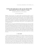
In this study we focus only on the humanoid robot for straight walking. So we fixed
the upper body of the robot and lower body have 10 controlled joints for the legs and
10 rotation joint angles 1 , 2 , 3 , 4 , 5 , 6 , 7 , 8 , 9 , 10 are defined as shown in
Figure 2.1. The position of the joints (P1, P2, P3, P4, P5, P6, P7, P8, P9, P10) is also
defined in Figure 2.1. As to humanoid robot stable walking, it needs to plan a
walking pattern generation for humanoid robot in the walking step period. The
walking pattern is a set of time series of joint angles for desired walking, and to
create it, we use a walking pattern generator (WPG). The walking pattern generator
consists of the generater the two foot trajectorys, hip trajectory and the inverse
kinematics. The Zero Moment Point ZMP standard is used to maintain stability with
accurate preset foot lifting magnitude.
6
Figure 2.1: Humanoid robot structure
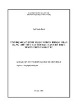
2.2.1 Generated Trajectories of Two Foots and Hip
Four most important variables of the humanoid robot that play an essential role in
stable gait generation, including S – walking step length, H – Leg lifting [m], h – Leg
kneeling [m] and n – Hip swinging, are clearly described in Figure 2.2. In which, d0
represents the height of the torso, d1 is the distance between the 2 dof at the knee
joints, d2 is the length of the leg, d3 is the length of the femoral and d4 represents the
distance between 2 hips.
Figure 2.2: Four key variables determine the human walking gait of humanoid robot.
7
As described in Figure 2.2, the total three trajectories of biped, including hip
trajectory P5 P5 x , P5 y , P5 z and ankle trajectory P1 P1x , P1 y , P1 z of the
supporting leg, and ankle trajectory P10 P10 x , P10 y , P10 z of the moving legs, will
depend on 4 variables (S, H, h, n) with respect to both of the frontal (YZ-Frontal
View) and sagittal (XZ-Sagittal View) interface. The three selected trajectories P1 ,
P5 , P10 are considered as sine-time dependent, and described in the equation (2.1),
(2.2) và (2.3).
P1x t S sin . t T .[u (t 2T ) u (t T )]
2
T 2
P1 y t w.[u (t 2T ) u (t T )]
P1x t
P
t
H
sin
.
0.5
.[u (t 2T ) u (t T )]
1
z
S
P10 x t S sin . t T .[u (t ) u (t T )]
2
T 2
P10 y t w.[u (t ) u (t T )]
P10 x t
P10 z t H sin . S 0.5 .[u (t ) u (t T )]
S T
P5x t sin ,
4 T 2
T
P5 y _ first _ half _ cycle t n sin . u u
T
2
T T
n cos . u u T ,
T
2
2
P5 y t P5 y _ first _ half _ cycle t .[u(t) u(t T )]
P5 y _ first _ half _ cycle t .[u(t 2T ) u(t T )],
P6z t d1 d2 d3 d4 h .
8
(2.1)
(2.2)
(2.3)
In which, T represents the time to perform a step of the humanoid robot, w represents
the
distance
between
2
legs,
t
t T
if 0 t T
otherwise
and
if t 0
0
u t
.
otherwise
1
From equations (2.1-2.2-2.3), both of hip and ankle trajectories of the supporting leg
and ankle trajectory of the moving leg are used to generate walking gait for the
humanoid robot.
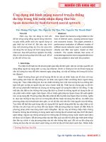
2.2.2 Biped Inverse Kinematics
Finally, the trajectories of the ten angular joints located at the 2 legs in one walking
interval cycle can be defined from P1 P1x , P1 y , P1 z , P5 P5 x , P5 y , P5 z và
P10 P10 x , P10 y , P10 z based on the biped inverse kinematics. The biped inverse
kinematics can be conventionally solved by calculus or numerical methods.
However, in this section, the geometric method based on the humanoid robot rotary
joint will be shown, as described in the equation (2.4).
yl t
1 t arctan
, 5 t 1 t ,
zl t
t arctan yr t , t t ,
6
10
10
zr t
3 t A t , 8 t C t ,
(2.4)
xl t
4 t 2 A t B t arcsin l t ,
l
x t
7 t C t D t arcsin r ,
l t
2
r
2 t 3 t 4 t , 11 t 9 t 7 t
which, yl t , zl t , yr t , zr t , A t , B t ,C t , D t , xl t , xr t , ll t , lr t at
specified time t, are defined as in Figure 2.3 và equation (2.5);
distance between
ll represents the
P2 and P4 , lr represents the distance between P9 and P7 .
9
Figure 2.3: Variables defined in formula (2.4).
xl P5 x P1x , yl P5 y P1 y , zl P5 z P1z ,
l P P 2 P P 2 P P 2 ,
4x
2x
4y
2y
4z
2z
l
xr P6 x P10 x , yr P6 y P10 y , zr P6 z P10 z ,
2
2
2
lr P7 x P9 x P7 y P9 y P7 z P9 z
2
2
2
arccos d 2 d 3 ll , arccos d3 sin A ,
A
B
ll
2d 2 d 3
2
2
2
d3 sin C
d 2 d 3 lr
C arccos
.
, D arccos
ll
2d 2 d 3
In which
d1 , d 2 , d 3 and d 4 are illustrated in Figure 2.2. The coordination
P6 x, y, z is calculated based on
x, y , z ,
[ P1 x, y, z ,
[ P2
(2.5)
P5 x, y, z , and the coordination of
P4 x, y, z , P7 x, y, z , P9 x, y, z ] is calculated based on
P5 x, y, z , P6 x, y, z , P10 x, y, z ] and the rotrary angle
[ 1 , 5 , 6 , 10 ]. Equations (2.6) below are used to determine P2 ,
10
P4 , P6 , P7 , P9 .
P2 x
P4 x
P6 x
P7 x
P
9x
P1x , P2 z d1 cos 1 , P2 y P2 z sin 1 ,
P5x , P4 z P5z d4 cos 1 , P4 y P5 y P5z P4 z sin 1 ,
P5x , P6 y P5 y w, P6 z P5z ,
(2.6)
P6x , P7 z P6 z d4 cos 10 , P7 y P6 y P6z P7 z sin 10 ,
P10 x , P9 z P10 z d4 cos 10 , P9 y P10 y P9 z P10 z sin 10 .
In summary, using the equations (2.4-2.5-2.6), the ten trajectories of the rotary angles
located at the 2 legs of biped HUBOT-5 in one interval walking cycle are computed
to accurately and efficiently control the biped walking gait.
Table 2.1. Pseudo-code of MDE
1.
2.
3.
4.
5.
6.
7.
8.
9.
10.
Begin
Initialization
Evaluation
For G=1 to GEN do
For i =1 to NP do
jrand= randint(1, D)
F = rand[0:4; 1:0], CR = rand[0:7; 1:0]
For j =1 to D do
If rand[0,1] < CR or j == jrand then
If rand[0,1] > threshold then
r r2 r3 i
11.
Select randomly 1
u i , j , G 1 x r 1,j , G F ( x r 2, j ,G x r 3,j , G )
12.
13.
Else
r r2 best i
14.
Select randomly 1
15.
ui , j ,G 1 xbest,j ,G F ( xr1,j ,G xr 2,j ,G )
16.
17.
18.
End if
Else
u i , j , G 1 x i,j , G
19.
20.
End if
End for
21.
If
22.
23.
24.
f U *i ,G 1 f X i ,G
X i ,G 1 U *i ,G 1
Else
then
X i ,G 1 X i ,G
25.
End if
26.
End for
27. End for
28. End
11
2.3 Proposed Gait Parametric Optimization Using MDE
2.3.1 MDE Algorithm
MDE algorithm was developed based on a DE algorithm has been introduced in 1997
by Storn and Price. The pseudo-code of DE. The pseudo-code of proposed modified
differential evolution (MDE) is developed from Son et al. and clearly described in
Table 2.1. In the MDE algorithm, X i ,G = [ x1, i ,G , …, x j, i ,G , …, xD, i ,G ] and U i ,G =
[ u1, i ,G , …, u j, i ,G , …, uD, i ,G ] represent the target and the
trial vector (D-
dimensional) of the i individual in G generation, x j, i ,G and ui , j ,G represent the jth
th
th
element of the target and the trial vector, the parameters F (the mutation scale
factor), CR (the crossover rate) are chosen randomly for each individual and for each
step, f represents the cost function, with G = 1, 2, …, Gmax represents the number of
generation, and i = 1, 2, …, NP denotes the size of population, j = 1, 2, …, D
represents the number of parameter.
2.3.2 Objective Function
To evaluate human gait parameters of the humanoid robot, one must define the
objective function. The goal of humanoid robot is to achieve a stable gait with preset
foot-lifting value. For this purpose, the ZMP point is always within the foot area.
If the ZMP is within the area of the supporting leg, the robot does not fall. The
calculation of the ZMP of biped robots in walking is shown in section 2.2.3.
The stability of the human robot is quantified by the distance of the ZMP and the
center of the foot in the step cycle. Walking gait with maximum stability are obtained
by minimizing the function f1 in equation (2.7):
T
2
2
f1 xZMP
yZMP
.dt
0
withT denotes stepping cycle and
xZMP , yZMP
(2.7)
denotes the coordination of ZMP
point in the robot's process of stepping away from the quadrant in the center of the
foot. The equation (2.7) is the first objective function.
Additionally, for the humanoid robot to follow the pre-set foot-lifting height value –
H ref , the difference between the magnitude of the foot-lift parameter - and the footlift preset value – H ref (see Equation 2.8) represents the second objective function.
f 2 H ref H
(2.8)
Thus, in order for biped robot to obtain a steady gait with the foot-lift set up in
advance, we find the minimum value of the two objective functions f1 and f 2 , or
similarly to find the minimum of the function f as:
12
T
2
2
1 . H ref H
f . xZMP
y
.
dt
ZMP
0
Fx1 xZMP Fx 2 ; Fy1 xZMP Fy 2
(2.9)
In which, Fx1 Fx 2 and Fy1 Fy 2 is the length and width of the robot foot,
0 1 is optimally selected as to prioritize between the walking stability (
increase) and the variance with the desired foot-lifting magnitude ( decreased).
2.3.3 Zero Moment Point (ZMP) Calculation
For small-sized biped robot, assuming the inertia and absolute angular acceleration
of the links are small enough to be ignored, the ZMP formula is calculated as (2.10):
n
n
m x z i1 mi xi zi
i 1 i i i
xZMP xCOM
n
i1 mi
(2.10)
n
n
m
y
z
m
y
z
i
i
i
i
i
i
i 1
i 1
yZMP yCOM
n
m
i1 i
2.4 Simulated and Experimental Results
The simulated and experimental results are fully tested on the small-sized HUBOT-5
biped robot (Fig 2.4).
Fig 2.4: Photograph of small-sized humanoid robot (HUBOT-5)
In order to find the most appropriate value for the coefficients of the objective
function in Equation (2.9), it optimally selects 0.4 which permits the HUBOT-5
biped robot attaining a steady gait with an adjustable foot-lift value, and this value
will be used thorough the comparative testing process using GA, PSO and MDE.
13
The mathematical properties of GA, PSO and MDE optimization algorithms are
meta-heuristic algorithms, so each algorithm will perform 10 different training times,
with each training will repeat 500 times (N = 500) using the same population size
(NP = 30) and the same number of variables (n = 4). Table 2.2 eventually presents
the GA, PSO and MDE selected parametric values.
Table 2.2: Parameters of GA, PSO and MDE Algorithm
Method
Paramters
Value
GA
Mutation Probability (MP)
0.4
Crossover Probability (CP)
0.9
PSO
Accelaration factor (C1)
2.0
Accelaration factor (C2)
2.0
Inertia Weight (w)
[0.4; 0.9]
MDE
Mutation value (F)
Random [0.4; 1.0]
Crossover Probability (CR)
Random [0.7; 1.0]
Figure 2.5: Mean value of fitness convergence f
Specify the foot-lifting height of biped HUBOT-5 being H ref 20mm . Figure 2.5
illustrates the mean value of the target function after 10 runs of each algorithm (GA:
green, PSO: blue, MDE: red). Table 2.3 shows the optimum gait value and the best
value for the target function of 10 runs corresponding to the GA, PSO and MDE
algorithms. Figure 2.6 shows resulted comparative ZMP and COM trajectories when
HUBOT-5 steps along with a stepping cycle (T=2s) with respect to the
configurations based on GA, PSO and MDE algorithms, respectively.
14
Table 2.3: Resulted parametric set for four comparative algorithms
Href = 2 cm
Agorithms
Walking Gait Parameters value
Best firness
value f(cm)
S (cm)
H (cm)
h (cm)
n (cm)
GA
15
2.05
1.000
7.08
14.88
PSO
15
2.00
1.040
6.91
14.87
MDE
15
2.00
0.804
6.89
14.87
ZMP & COM
10
5
COM-GA
ZMP-GA
COM-PSO
ZMP-PSO
COM-MDE
ZMP-MDE
Y-axis(cm)
0
-5
-10
-15
-15
-10
-5
0
5
10
15
20
X-axis(cm)
Figure 2.6: Resulted comparative ZMP and COM survey
The optimal set of four key parameters for four comparative algorithms presented in
Table 2.3 shows that the target is reached with respect to the preset foot-lift value.
The ZMP and COM trajectories corresponding to each of the four comparative
algorithms presented in Figure 2.6 show that they are always within the footprint and
this means that biped HUBOT-5 are achieving steady-state stable and robust
walking.
Based on the results described in Figure 2.5, it is important to notice that the MDE
algorithm searches for an optimal solution with an average value of 14.8706495 after
about 144 generations, while the PSO algorithm is approximately 254 generations
after the search, finding an optimal solution obtained an average value of 14.87065,
while the GA algorithm must need around 465 generations to find the optimal
solution with an average value of 14.88492. These results show that the MDE
algorithm outperforms GA and PSO algorithms in terms of convergence speed.
Table 2.4 demonstrates the optimized value of the walking gait parameters to ensure
the biped HUBOT-5 to walk steadily with both cases corresponding to differnet
preset foot-lift magnitude. ( H ref 2cm and H ref 4cm ) optimized by MDE
algorithm.
15
Href
(cm)
2.0
4.0
Table 6. Optimal parameter set
MDE optimization Results
S (cm)
H (cm)
h (cm)
n (cm)
15
0.8040
6.89
2.0
15
0.7950
6.86
4.0
Figure 2.7 illustrates the 2D gait in the X-Z plane of the HUBOT-5, corresponding to
two cases with different preset foot-lifting amplitudes. Tables 2.4 and Fig. 2.7 show
that the biped HUBOT-5 attains a pickup lift in term of the preset value.
Hình 2.7. Simulated 2D gait result of biped HUBOT–5 with different preset footlifting amplitudes
Figure 2.8: Resulted ZMP và COM trajectories
16
Figure 2.8 illustrates the resulted ZMP point trajectory and the projection of COM
trajectory for two different preset foot-lifting amplitudes. This result shows that the
ZMP point is always in the supporting foot area and then it ensures that the HUBOT5 biped robot surely keeps stable walking.
Figure 2.9 demonstrates the ten rotary angular trajectories in one stepping cycle of
the two legs of biped HUBOT–5 1 , 2 ,3 , 4 , 5 , 6 , 7 ,8 ,9 ,10 during walking with
two optimally resulted sets of gait parameters with respect to two different preset
foot-lift values. Using ten rotary angular values to control the biped HUBOT-5, it
performs two corresponding steps with two different foot-lift values. Figures 2.10 (a,
b) illustrate the photos of the HUBOT-5 biped robot in performing a stable and
steady walking step with respect to the two foot-lift values H ref 2cm and
5(rad)
4(rad)
3(rad)
2(rad)
1(rad)
10(rad)
9(rad)
8(rad)
7(rad)
6(rad)
H ref 4cm .
Figure 2.9: Trajectories of the ten joint angles located at two legs of biped HUBOT-5
a)
b)
Figure 2.10: Photos of biped HUBOT-5 performing stable gait
Based on the results of the optimization and simulation shown in Table 2.4, Figure
2.7 and Figure 2.8, as well as the experimental results presented in Figure 2.9 and
17
Figure 2.10, which once more demonstrate that the work of preset foot-lifting
parameter - Href and four optimally selected parameters (S-step length, H-foot
lifting, h – kneeling, and n – hip swinging) ensuring the HUBOT-5 biped robot to
steadily walking without falling apart and keeping pace with desired foot-lift
amplitude. The proposed algorithm with gait parameters optimized by MDE
algorithm is convincingly feasible.
2.6 Conclusion
This paper innovatively proposes a new algorithm based on four key gait parameters
that enable dynamic equilibrium in stable walking for nonlinear uncertain humanoid
robots of which gait parameters are initiatively optimized with MDE algorithm. First,
the inverse kinematics is used to estimate the position of the actuators located in the
joints of the two legs of biped. Then, the MDE optimization algorithm is applied to
find the best solution for biped gait parameters so that the ZMP distance to the center
of the supporting foot attains the smallest with respect to the preset foot-lifting value.
The simulated and experimental results of proposed algorithm applied on the smallsized biped HUBOT-5 robot demonstrate the performance of novel algorithm
allowing the biped robot to move steadily with an effectively reduced training time.
Adaptive Gait Generation for Humanoid Robot Using
Evolutionary Neural Model Optimized with Modified Differential
Evolution Technique
CHAPTER 3
3.1 Introduction
While the human robot walks, the 4 parameters of the WPG of Dip are unchanged.
This makes robot humanoid difficult to perform a stable and natural walk with a
desired ZMP trajectory (Zero Momen Point). To overcome this challenge, the author
identifies and controls these 4 parameters of the WPG using adaptive evolutionary
neural model (AENM) optimized Modified Differential Evolution (MDE).
Simulation results on the small-sized human robot models (HUBOT-5) prove the
thesis's proposal is feasible
Fig. 3.1: Proposed control scheme using novel Adaptive evolutionary neural
model (AENM)
18
3.2 Adaptive evolutionary neural model (AENM) identified and optimized by
modified differential evolution (MDE) algorithm
In this chapter, an adaptive evolutionary neural model is proposed to generate the
input parameter for walking pattern generator (see Fig. 3.1). A Walking pattern
generator was described by Goswami Dip as described in section 2.2. An adaptive
evolutionary neural model using nonlinear auto-regressive with exogenous input
(NARX) model is proposed. The outputs of neural network are the inputs of walking
pattern generator that generate rotation angles for biped robot. The output of biped
robot is x, y coordinates of the ZMP value (calculated as described in section 2.3.3).
Those parameters will be feedback to neural network with desired ZMP coordinates.
The parameters of neural model will be optimally identified by modified differential
evolution algorithm (MDE). The neural network system has 4 inputs
(desiredZMPx[n], DesiredZMPy[n], ZMPx[n-1] and ZMPy[n-1]) and 4 outputs
(S,H,h,n).
The outputs of neural model are described as:
neth [n] vT [n]x[n] bh
1 eneth
1 eneth
neto [ n] wT yh [ n] bo
yh [ n]
yo [ n] neto [n]
Where, neth is sum of input (x) with weight (v) and bias (bh) before going through an
activation function. yh is output of the hidden layer.., yo represents output of the
output layer, the output is the same as neto function is sum of output hidden layer (yn)
with weight (w) and bias (bo).
Thus the basic four parameters H, h, s and n are to be optimally chosen so that the
biped ZMP are guaranteed, thereby helping the biped robot to steadily walk along
with a ZMP reference trajectory.
3.4 Identification Results of Biped Gait Generation Using AENM Model
Fig. 3.2: Proposed AENM neural model
19
The proposed AENM neural model has been designed with 8 neural in hidden layer,
4 inputs and 4 outputs with its structure is presented in Figure 3.2. The neural
network model operated as a close-loop controller guarantee humanoid robot
walking stable. The inputs are the one-step delay x, y (x[n-1], y[n-1]) coordinates of
the ZMP and the desired x, y (xd[n], yd[n]) coordinates of the ZMP. The outputs are 4
parameters (S[n], H[n], h[n], n[n]) those are themselves the input of the walking
pattern generator.
The parameters of proposed AENM neural model will be optimally identified using
evolutionary optimization MDE algorithm. The cost function is calculated based on
the least mean square (LMS) error criteria.
f
X
Total Sample
1
desiredX zmp Yzmp desiredYzmp
2
zmp
2
(3.1)
For the beginning, the parameters of AENM neural model are initialized randomly.
Eventually, the parameters of AENM neural model are optimally updated with the
four output values (S, H, h, n) being the inputs of walking pattern generator, which
will generate the ten joint angle values for biped robot walking control. Since ZMP
criteria is chosen to ensure the biped walking stability, ZMP calculated from AENM
neural model is compared with the desired ZMP. Then the cost function is calculated
as in (3.1). The equation (3.1) shows that the smaller value of the cost function
becomes the more robust and precise of the proposed AENM neural model attains.
The comparative results derived for three tested algorithms, namely PSO, GA and
proposed MDE, will be fully presented. Each meta-heuristic algorithm is applied to
train the neural network model 10 times with different randomly initial parameters.
Each training process will run with exactly 200 generations for comparison purpose.
The parameters of three optimization algorithms are comparatively tabulated in
Table 3.1 The parameters c1, c2 represent learning factors and w denotes forgetting
factor of the PSO optimization algorithm. In case the GA algorithm, parameter CP
represents the crossover probability and MP value represents the mutation
probability, respectively.
Table 3.1: Principal parameters of comparative optimization algorithms
PSO
GA
MDE
c1 0.001 CP 0.9
F Random [0.4; 1.0]
c2 0.05 MP 0.01 CR Random [0.7; 1.0]
w
0.8
Figure 3.3 presents the comparative results of the fitness convergence of three tested
algorithms, namely PSO, GA and proposed MDE in logarithm calibration. The green
colour represents PSO fitness convergence, in which, green dash line is the average
fitness convergence calculated from 10 green dot lines. The same way, the blue
colour represents GA fitness convergence, in which, blue dash line is the average
fitness convergence determined from 10 blue dot lines. Eventually the red colour
20
represents proposed MDE fitness convergence, in which, red dash line is the average
fitness convergence calculated from 10 red dot lines.
In Figure 3.3, the comparative results of the fitness convergence show that the PSO
algorithm has been trapped into a local minimum solution and then it is impossible to
successfully identify the proposed AENM model. Meanwhile GA and MDE prove
successful to obtain the global solution. The red line of GA-based convergence and
the blue line of proposed MDE-based convergence give better results than the green
line. Furthermore, in comparison between GA and proposed MDE, Figure 3.3 shows
that the proposed MDE-based fitness convergence proves rather better than the GA
optimisation algorithm.
10 6
PSO:Green; GA: Blue; MDE: Red
FitnessValue
10 5
10 4
10 3
10 0
10 1
10 2
Generations
Fig 3.3 Comparative fitness convergence results
In Fig 3.4 shows the comparative results between the response ZMP trajectory of
proposed AENM model and the desired ZMP trajectory. It is clear to see that blue
colour and red colour results represent the ZMP trajectory response of proposed
AENM model trained with GA and MDE algorithm, respectively. Furthermore, it is
evident to confirm that blue line and red line follow the desired ZMP trajectory
strongly better than the green line which represents the ZMP response of proposed
AENM model after trained with PSO.
Table 3.2 shows the comparative training results of PSO, GA, and MDE. Based on
average results from ten tested runs, MDE fitness value proves better than GA about
14.9% and faster than GA 3.8%. Using comparative results tabulated in Table 3.2, it
is evident to conclude that the proposed MDE algorithm proves the best precise and
robust capabilities in comparison with the PSO and GA algorithms.
21
Fig 3.4: Comparative results of responding ZMP and desired ZMP trajectory
Table 3.2: Comparison training results
PSO
GA
MDE
Min.
1.1381e+04
1.3099e+03
1.2987e+03
Avg.
2.3271e+04
1.5888e+03
1.3825e+03
Max.
3.5075e+04
1.9121e+03
1.6370e+03
Variance
0.7820e+04
0.2660e+03
0.1035e+3
Time (second)
5413.2
5212.9
5193.3
Figure 3.5 shows the comparative results of rotation angle of 10 joints of biped robot.
From Figure 3.5, we can notice that the fitness value of the GA rather close to the
MDE. The fact is that this small difference has made a decisively significant impact
to a humanoid robot in stable and robust walking. The rotation angle of 3 and 8
resulted from GA have changed greater than MDE ones. As a consequent these
results have made the humanoid robot not only to require more energy consuming
but also to suffer less stable in walking in comparison with MDE based identified
results.
The best fit weighting values of proposed AENM model optimally trained by MDE
algorithm are shown in Table 3.3. This table shows that vij represents the weighting
value of input hidden layer, where i from 1 to input number, j from 1 to number of
neural in hidden layer, respectively; bh denotes bias of hidden layer; eventually wij
represents the weighting value of input output layer, where i from 1 to number of
neural in hidden layer, j from 1 to output number; bo represent bias of output layer.
22