Hệ thống thủy lực máy đào CATERPILLAR SERIE D - P9
Bạn đang xem bản rút gọn của tài liệu. Xem và tải ngay bản đầy đủ của tài liệu tại đây (1.11 MB, 59 trang )
SERV1852-02
August 2008
GLOBAL SERVICE LEARNING
TECHNICAL PRESENTATION
320D-336D HYDRAULIC EXCAVATORS TIER III ENGINES
TRAVEL SYSTEMS
Service Training Meeting Guide
(STMG)
320D-336D HYDRAULIC EXCAVATORS TIER III ENGINES
TRAVEL SYSTEMS
AUDIENCE
Level II - Service personnel who understand the principles of machine systems operation,
diagnostic equipment, and procedures for testing and adjusting.
CONTENT
This presentation provides an introduction and describes the components and systems operation
of the 320D - 336D hydraulic excavator Travel Systems. Additional presentations will cover
the machine walkaround, engines, pilot system, pumps and controls, main control valve group,
swing system, and tool control systems in more detail. This presentation may be used for selfpaced and self-directed training.
OBJECTIVES
After learning the information in this presentation, the technician will be able to:
1. identify the correct operation of the Travel Systems on the 320D-336D hydraulic
excavators, and
2. diagnose problems in the Travel Systems.
REFERENCES
320D Hydraulic Excavator Specalog
323D L and 323D LN Hydraulic Excavators
324D Hydraulic Excavator Specalog
325D Hydraulic Excavator Specalog
328D Hydraulic Excavator Specalog
330D Hydraulic Excavator Specalog
Machine Monitoring System - Systems Operation
Self-study "300D Series Hydraulic Excavators, 345C Hydraulic Excavator,
and 365C & 385C Large Hydraulic Excavators
iTIM " '300C' Series Hydraulic Excavators-Electronic Control Systems"
iTIM "325C Hydraulic Excavators-Hydraulic Systems"
325D Hydraulic Schematic
Estimated Time: 1 Hour
Illustrations: 30
Form: SERV1852-02
Date: August 2008
© 2008 Caterpillar
AEHQ5856
HEHH3327
AEHQ5663
AEHQ5665
AEHQ5706
AEHQ5667
RENR8068
SERV7032
SERV2693
SERV2701
KENR6157
SERV1852-02
08/08
-3-
Text Reference
Travel Systems
TABLE OF CONTENTS
INTRODUCTION ........................................................................................................................5
TRAVEL SYSTEMS COMPONENTS ........................................................................................6
320D-329D TRAVEL SYSTEMS OPERATION.......................................................................13
Travel Motor .........................................................................................................................13
Travel Parking Brake and ....................................................................................................20
320D Travel Brake Valve......................................................................................................22
Makeup Operation ................................................................................................................28
330D/336D TRAVEL SYSTEMS OPERATION .......................................................................29
Travel Motor .........................................................................................................................29
Travel Parking Brake ...........................................................................................................36
321D-336D Travel Brake Valve ...........................................................................................38
Makeup Operation ....................................................................................................................
STRAIGHT TRAVEL VALVE ...................................................................................................45
SWIVEL .....................................................................................................................................53
FINAL DRIVE............................................................................................................................55
CONCLUSION ..........................................................................................................................54
SERV1852-02
08/08
-4-
Text Reference
Travel Systems
PREREQUISITES
"Fundamentals of Mobile Hydraulics Self Study Course"
"Fundamentals of Power Train Self Study Course"
"Fundamentals of Electrical Systems Self Study Course"
"Fundamentals of Engines Self Study Course"
TEMV3002
TEMV3003
TEMV3004
TEMV3001
NOTES
Nomenclature Change: During the fourth quarter of 2008, the 325D and 330D
nomenclature changed. The 325D became the 329D and the 330D became the 336D for
most arrangements.
The exceptions are as follows:
- The nomenclature for the 325D MH and 330D MH did not change.
- The nomenclature for the 325D FM and 330D FM did not change.
- The 325D HD HW did not change into 329D HD HW. This model is being discontinued.
However, the 330D HD HW changed to the 336D HD HW.
SERV1852-02
08/08
-5-
Text Reference
Travel Systems
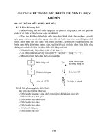
TRAVEL SYSTEMS
Stick Cylinder
Bucket Cylinder
Swing Motor
Main Control Valve Group
Pilot
Control
Valves
Priority
Valves
Pilot Manifold
Pilot
Pump
Fan
Motor
Boom Cylinders
Travel Motors
Main
Hydraulic
Pumps
M
Fan
Pump
Tank
The Fan Motor and Pump are only used on the 330D and the 336D
1
INTRODUCTION
This presentation covers the 320D - 336D hydraulic excavator Travel Systems. Both the drive
pump and idler pump are used to provide flow to the Travel Systems.
The Travel Systems includes the following components:
- travel pedals/levers
- travel pilot valves
- left and right travel control valves
- straight travel valve and solenoid
- two travel motors
- travel park brake
- two speed travel solenoid valve
NOTE: The 330D and 336D travel motor is slightly different in operation than the
travel motors used in the smaller machines. The 330D and 336D travel motor will be
covered in a revision to this section.
SERV1852-02
08/08
-6-
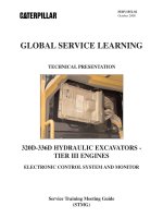
TRAVEL HYDRAULIC SYSTEM
Left Travel
Motor
Right Travel
Motor
Text Reference
Travel Systems
NEUTRAL
Straight
Travel Solenoid
Swivel
Left
Straight
Travel
Control
Valve
Right
Travel
Pilot
Valves
REV
FWD
FWD
Right
Travel
Valve
Left
Travel
Valve
Main
Relief
Valve
REV
AEC
Idler
Pump
Travel
Speed
Solenoid
Valve
Swing
Brake
Solenoid
Pilot
Pump
M
Hydraulic
Activation
Valve
Implement
Hydraulic
Lockout
Solenoid
Drive
Pump
Pilot
Manifold
2
TRAVEL SYSTEMS COMPONENTS
The idler pump and drive pump supplies oil flow to the travel control valve circuit, which
controls pump flow to the two travel motors.
When the travel control valves are in NEUTRAL, pump supply oil from the pumps flows
through the center bypass passage in the travel valves through all other control valves (not
shown) to the NFC valves (also not shown). The return oil from the pumps through the bypass
passages (neutral envelopes of the valve) creates NFC signals used to destroke the pumps.
Pilot oil is available at the travel speed solenoid valve.
Since the implement hydraulic lockout solenoid has been energized, the hydraulic activation
valve has shifted. Pilot oil is directed to the travel pilot valves.
SERV1852-02
08/08
-7-
Text Reference
Travel Systems
Some of the major components of the Travel Systems include:
Two Speed Travel Solenoid Valve: This solenoid valve is controlled by the Machine ECM.
The valve controls the position of the displacement change valve in each motor to select slow
or fast travel speed.
Travel Pilot Valves: The valves direct pilot oil to shift the travel valves in the main control
valve group. The pilot valves are shifted by either pedals or levers.
Straight travel control valve and solenoid: When both travel control valves are shifted or
one travel valve and an implement/swing circuit are activated, the solenoid is energized to
provide flow priority to the travel motors.
Slow Return Check Valve: The back pressure created by the slow return check valve ensures
that makeup oil is present at the travel motor and the various makeup valves in the hydraulic
system.
SERV1852-02
08/08
-8-
Text Reference
Travel Systems
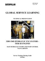
3
2
1
3
4
8
7
5
6
4
Left travel valve (1) and right travel valve (2) are used to control the travel motors. The
straight travel valve (3) provides flow priority for the Travel Systems during a travel condition.
The slow return check valve is part of the slow return check valve and cooler bypass
manifold (4).
The Travel Systems uses foot pedals (5 and 6) or travel levers (7 and 8) to control the direction
of machine travel.
SERV1852-02
08/08
-9-
Text Reference
Travel Systems
2
3
5
5
6
1
4
9
7
6
8
Each track is driven by a travel motor (1). A counterbalance valve (2) prevents overspeed while
the machine is traveling downhill, prevents shocks to the system when travel is stopped, and
helps to prevent motor cavitation.
Crossover relief valves (3 & 4) are used to protect the travel motor from pressure spikes.
The upper supply line (5) directs supply oil to the motor for reverse travel, while the lower
supply line (6) directs supply oil to the motor for forward travel.
The final drive is composed of a three-stage planetary gear reduction to reduce the motor speed
to drive the track. Fill (8) and drain (9) plugs are in the outer cover.
SERV1852-02
08/08
- 10 -
Text Reference
Travel Systems
1
3
2
7
The two speed travel solenoid valve (1) is part of the pilot manifold. The manifold is located
directly below the main control valve.
The hydraulic activation solenoid (2) must energize to shift the hydraulic activation valve (3).
If the hydraulic activation valve is not shifted there is no pilot oil to the the travel pilot valves.
SERV1852-02
08/08
- 11 -
Text Reference
Travel Systems
2
1
8
When the two-speed travel soft switch (1) is located on the soft switch panel (2).
When the two-speed travel switch is pushed , the travel speed is toggled between the Slow and
Fast Speed Modes.
- The rabbit indicator is for fast or high speed.
- The tortoise indicator is for slow or low speed..
The Fast Speed Mode is also called the Automatic Mode. The Machine ECM senses the drive
pressure and will automatically change the travel speed from the Fast Speed Mode to the Slow
Speed Mode, when the drive pressure exceeds a predetermined limit.
For instance, by putting the machine automatically into the Slow Speed Mode, more torque is
available for climbing slopes.
Once the drive pressure drops again below the predetermined limit, the Machine ECM will
automatically return the machine to the Fast Speed Mode.
SERV1852-02
08/08
- 12 -
Text Reference
Travel Systems
TRAVEL PILOT CONTROL VALVE
Pedal
Rod
Orifice
Check
Valve
Dampening
Piston
Dampening
Piston
Pilot Supply
Left
Right
Tank
Metering
Spring
Spool
Return
Spring
Pilot
Supply
REV
FWD
aL1
bL1
Travel Pressure
Switch (AEC)
Travel
Valve
FWD
bR1
REV
aR1
Resolver
Travel
Valve
9
The travel pilot control valve operates similar as the implement pilot valves (joysticks).
Depending on how far the travel pedal or lever is moved will determine the amount of pilot oil
directed to the respective travel control valve.
A dampening function is built into the travel pilot control valve which allows the operational
speed of the travel lever/pedal to respond only to intended movements of the operators foot.
The dampening function also prevents the vibration that occurs when the travel lever/pedal is
released.
When the travel lever/pedal is moved from the NEUTRAL position, the rod is pushed
downward. The rod moves the dampening piston downward. The hydraulic oil below the
dampening piston is pressurized.
An orifice check valve allows the trapped hydraulic oil below the dampening piston to
gradually flow into the metering spring chamber, which is open to the tank. The gradual flow
of oil through the orifice check valve provides the dampening function.
SERV1852-02
08/08
- 13 -
Text Reference
Travel Systems
LEFT TRAVEL CONTROL VALVE
NEUTRAL
Port A
Port B
Bridge
Passage
Feeder
Passage
Travel
Spool
NFC
Signal
Center
Bypass
Passage
10
The travel control valves do not use a load check valve due to a counterbalance valve in each
travel motor.
Also due to the counterbalance valve, the lines to the motor are drained to tank in NEUTRAL
past lands on the end of the travel spool. The counterbalance valve blocks the oil in the travel
motors from going to the tank.
Due to the travel valves being the first control valves to receive supply oil, the valves receive
supply oil directly off of the center bypass passage through the feeder passage and into the
bridge passage. The travel valve blocks the oil in the bridge passage.
Since the travel valve is not shifted, supply oil through the center bypass passage flows to
through main valve group. Some of this supply oil is used to destroke one of the hydraulic
pumps.
NOTE: The illustration above is for the left travel control valve only. The right travel
control valve should operate similarly, but the drawings shown in the Parts Manual and
other publications makes the valve appear to function differently.
SERV1852-02
08/08
- 14 -
Text Reference
Travel Systems
LEFT TRAVEL CONTROL VALVE
SHIFT - FORWARD
Port A
Port B
Bridge
Passage
Feeder
Passage
Travel
Spool
Pilot
Oil
NFC
Signal
Center
Bypass
Passage
11
When the travel pedal is depressed or the travel lever is moved for forward travel, pilot oil shift
the travel control spool.
The center bypass passage is blocked or restricted to reduce the NFC signal to the pump. The
pump upstrokes.
Supply oil in the bridge passage is directed by the travel spool to the travel motor. Return oil
from the motor is directed to the tank past the travel spool as well.
SERV1852-02
08/08
- 15 -
Actuator
Text Reference
Travel Systems
320D - 329D LEFT TRAVEL MOTOR
Max
NEUTRAL
Min
Parking
Brake
Two Speed Travel Switch
Displacement
Change Valve
Brake
Pilot Valve
Two Speed Travel
Solenoid Valve
Machine
ECM
Crossover Relief Valves
Pilot
Pump
Travel
Valve
Output
Pressure Sensor
U
Counterbalance
Valve
Slow Return
Check Valve
Power Shift
PRV Solenoid
Valve
12
320D-329D TRAVEL SYSTEMS OPERATION
Travel Motor
Some of the major components of the travel motor include:
Crossover Relief Valves: These valves dampen pressure spikes in the Travel Systems
whenever the travel is stopped. The valves also prevent or reduce travel motor cavitation.
Brake Pilot Valve: This valve controls the parking brake. Some of the supply oil is directed
to the brake pilot valve to release the park brake for machine travel. The valve also provides
for a gradual engagement of the parking brake when travel is returned to NEUTRAL.
Counterbalance Valve: This valve prevents overspeed while the machine is traveling downhill,
prevents shocks to the system when travel is stopped, and helps to prevent motor cavitation.
In NEUTRAL the counterbalance valve blocks the oil in the passages to the motor to prevent
the motor from rotating.
SERV1778
03/06
- 16 -
Text Reference
Displacement Change Valve: The displacement change valve is controlled by the two speed
travel solenoid valves. The displacement change valve controls the supply oil to shift one of
the motor actuators.
Motor Actuator Pistons: Two actuators are used to control the angle of the motor swashplate.
If the maximum actuator is shifted, the machine is in the Slow Speed Mode for travel. If the
minimum actuator is shifted, then the machine is in the Fast Speed Mode for travel.
SERV1852-02
08/08
- 17 -
Actuator
Text Reference
Travel Systems
320D - 329D LEFT TRAVEL MOTOR
Max
SLOW SPEED
Min
Parking
Brake
Two Speed Travel Switch
Displacement
Change Valve
Brake
Pilot Valve
Two Speed Travel
Solenoid Valve
Crossover Relief Valves
Machine
ECM
Pilot
Pump
Travel
Valve
Output
Pressure Sensor
U
Counterbalance
Valve
Slow Return
Check Valve
Power Shift
PRV Solenoid
Valve
13
When the operator selects the Slow Speed Mode, the Machine ECM will NOT energize the two
speed travel solenoid valve. The displacement change valve does not shift.
Some of the supply oil to the motors is sent by the displacement change valve to the actuator
piston on the right and drains the passage to the actuator on the left.
The motor swashplate is moved to the maximum angle resulting in the machine traveling in the
Slow Speed Mode.
SERV1852-02
08/08
- 18 -
Piston and
Barrel Assembly
Text Reference
Travel Systems
TRAVEL MOTOR
A
Max. Actuator
Swashplate
Piston
SLOW SPEED
Spring
C
B
B
View A-A
Min Max
Min. Actuator
Piston
Displacement
Change Valve
Separator Plates
and Friction Disks
Piston
Section B-B
A
Parking Brake
Piston
Section C-C
14
Two swashplate actuator pistons control the angle of the motor swashplate. The pistons are
controlled by the displacement change valve.
The angle of the swashplate will limit the maximum speed. Since the displacement change
valve has not been shifted by pilot oil, the upper actuator piston shifts to move the swashplate
to maximum angle. Moving the swashplate to minimum angle results in slower machine
speeds, but with higher torque.
For the motor to turn, the parking brake must be released. To release the brake some of the
supply oil is used to shift the parking brake piston against the parking brake spring.
The travel valves in the main control valve group direct oil to and from the motors.
SERV1852-02
08/08
- 19 -
Text Reference
Travel Systems
DISPLACEMENT CHANGE VALVE
MAXIMUM ANGLE - SLOW SPEED
Swashplate
Piston
Pilot
Oil
Two Speed Travel
Solenoid Valve
Piston
Chamber
Displacement
Change Valve
Left Drive
Loop
Right Drive
Loop
15
If the displacement change valve does NOT shift, supply oil to the motor is directed to the
maximum actuator piston on the right to hold the motor swashplate at maximum angle.
At maximum angle, the motors will displace more flow and turn at a slower speed and provide
more torque.
SERV1852-02
08/08
- 20 -
Text Reference
Travel Systems
320D - 329D LEFT TRAVEL MOTOR
Actuator
FAST SPEED
Max
Min
Parking
Brake
Two Speed Travel Switch
Displacement
Change Valve
Brake
Pilot Valve
Two Speed Travel
Solenoid Valve
Machine
ECM
Crossover Relief Valves
Pilot
Pump
Travel
Valve
Output
Pressure Sensor
U
Counterbalance
Valve
Slow Return
Check Valve
Power Shift
PRV Solenoid
Valve
16
When the operator selects the Fast Speed Mode, the Machine ECM will energize the two speed
transmission solenoid valve in the pilot manifold.
The two speed transmission solenoid valve directs the pilot pressure to shift the displacement
change valve to the left.
The displacement change valve directs some of the supply oil to the minimum angle actuator
piston on the left and drain the oil to the maximum actuator piston on the right. The motor
swashplate angle is reduced.
The Machine ECM receives feedback from the output pressure sensor. If the drive pressure is
too high, the Machine ECM will de-energize the two speed travel valve to put the machine into
the Slow Speed Mode.
With the two speed travel valve de-energized, the displacement change valve moves back to the
right and directs supply oil to the maximum angle actuator and drains the oil to the minimum
angle actuator to upstroke the motor for slower speed and higher torque.
As the drive pressure decreases the Machine ECM will automatically return the machine to the
Fast Speed Mode.