Hệ thống thủy lực máy đào CATERPILLAR SERIE D - P8
Bạn đang xem bản rút gọn của tài liệu. Xem và tải ngay bản đầy đủ của tài liệu tại đây (667.63 KB, 39 trang )
SERV1852-02
August 2008
GLOBAL SERVICE LEARNING
TECHNICAL PRESENTATION
320D-336D HYDRAULIC EXCAVATORS TIER III ENGINES
SWING SYSTEM
Service Training Meeting Guide
(STMG)
320D-336D HYDRAULIC EXCAVATORS TIER III ENGINES
SWING SYSTEM
AUDIENCE
Level II - Service personnel who understand the principles of machine systems operation,
diagnostic equipment, and procedures for testing and adjusting.
CONTENT
This presentation provides an introduction and describes the components and systems operation
of the 320D-336D swing system. Additional presentations will cover the machine walkaround,
engines, pilot system, main control valve group, implements, swing system, travel system, and
tool control systems in more detail. This presentation may be used for self-paced and selfdirected training.
OBJECTIVES
After learning the information in this presentation, the technician will be able to:
1. identify the correct operation of the swing system on the 320D-336D hydraulic
excavators, and
2. diagnose problems in the swing system.
REFERENCES
320D Hydraulic Excavator Specalog
323D L and 323D LN Hydraulic Excavators
324D Hydraulic Excavator Specalog
325D Hydraulic Excavator Specalog
328D Hydraulic Excavator Specalog
330D Hydraulic Excavator Specalog
Machine Monitoring System - Systems Operation
Self-study "300D Series Hydraulic Excavators, 345C Hydraulic Excavator,
and 365C & 385C Large Hydraulic Excavators
iTIM " '300C' Series Hydraulic Excavators-Electronic Control Systems"
iTIM "325C Hydraulic Excavators-Hydraulic Systems"
325D Hydraulic Schematic
Estimated Time: 1 Hour
Illustrations: 32
Form: SERV1852-02
Date: August 2008
© 2008 Caterpillar
AEHQ5856
HEHH3327
AEHQ5663
AEHQ5665
AEHQ5706
AEHQ5667
RENR8068
SERV7032
SERV2693
SERV2701
KENR6157
SERV1852-02
08/08
-3-
Text Reference
Swing System
TABLE OF CONTENTS
INTRODUCTION ........................................................................................................................5
Swing System Components ....................................................................................................6
Swing System Operation ......................................................................................................11
Swing Motor Operation ........................................................................................................18
Swing Drive ..........................................................................................................................34
CONCLUSION ..........................................................................................................................39
SERV1852-02
08/08
-4-
Text Reference
Swing System
PREREQUISITES
"Fundamentals of Mobile Hydraulics Self Study Course"
"Fundamentals of Power Train Self Study Course"
"Fundamentals of Electrical Systems Self Study Course"
"Fundamentals of Engines Self Study Course"
TEMV3002
TEMV3003
TEMV3004
TEMV3001
NOTES
Nomenclature Change: During the fourth quarter of 2008, the 325D and 330D
nomenclature changed. The 325D became the 329D and the 330D became the 336D for
most arrangements.
The exceptions are as follows:
- The nomenclature for the 325D MH and 330D MH did not change.
- The nomenclature for the 325D FM and 330D FM did not change.
- The 325D HD HW did not change into 329D HD HW. This model is being discontinued.
However, the 330D HD HW changed to the 336D HD HW.
SERV1852-02
08/08
-5-
Text Reference
Swing System
SWING SYSTEM
Stick Cylinder
Bucket Cylinder
Swing Motor
Main Control Valve Group
Pilot
Control
Valves
Priority
Valves
Pilot Manifold
Pilot
Pump
Fan
Motor
Boom Cylinders
Travel Motors
Main
Hydraulic
Pumps
M
Fan
Pump
Tank
The Fan Motor and Pump are only used on the 330D and 336D
1
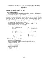
INTRODUCTION
This presentation covers the 320D-336D swing system. The swing system includes the
following components:
- swing control valve (part of the main control valve group)
- swing motor
- variable swing priority valve (part of the swing control valve)
- swing priority valve
- dual stage, swing line relief valves
- cushion crossover anti-reaction valves
- fine swing control solenoid valve (not available in EAME after October 2008)
- swing brake
- slow return check valve
The idler pump supplies flow for the swing system. The swing control valve is shifted by pilot
oil from the joystick pilot valves.
SERV1852-02
08/08
-6-
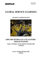
Swing
Brake
Swing Motor
Group
Text Reference
Swing System
SWING SYSTEM
Motor
Line Relief
Valve
SWING COMPONENTS - NEUTRAL
Makeup
Valve
Anti-Reaction
Valves
Fine Swing
Valve
Swing / Stick
Pilot Valve
Out
In
R
Variable
Swing
Priority
Valve
Swing
Control
Valve
Stick 2
Control
Valve
L
Idler
Pump
M
Drive
Pump
Swing Priority
Pressure Reducing
Valve
AEC Pressure
Switch
Swing
Brake
Solenoid
Slow Return
Check Valve
Pilot
Pump
Hydraulic
Activation
Valve
Implement
Hydraulic
Lockout
Solenoid
Pilot
Manifold
2
Swing System Components
The swing circuit controls the rotation of the swing motor. The idler pump provides the pump
flow for the swing circuit.
When either one of the joysticks is moved from the NEUTRAL position, the swing parking
brake is released. The swing motor is mounted on top of the swing drive. The swing drive is
installed on the upper structure and rotates the upper structure.
When the hydraulic activation control lever is in the UNLOCKED position, pilot pump oil
flows to the swing parking brake solenoid valve in the pilot manifold and to the swing pilot
control valve. Pilot oil from the pump also flows through the swing priority pressure reducing
valve to the variable swing priority valve and moves the variable swing priority valve fully up.
With the swing control valve in NEUTRAL, pump supply oil from the idler pump flows though
the center bypass valve of the swing control valve and all other control valves shown to the
NFC valve. The return oil creates a signal used to destroke the idler pump.
SERV1852-02
08/08
-7-
Text Reference
Swing System
The swing brake is currently on so the motor will not rotate.
Since the implement hydraulic lockout solenoid has been energized, the hydraulic activation
valve has shifted. Pilot oil is directed to the pilot joystick and to the swing brake solenoid.
Swing Priority Pressure Reducing Valve and Variable Swing Priority Valve: These two
valves work together to provide flow priority over the stick control valve when the stick and
swing are operated together.
Swing Parking Brake Solenoid Valve: When energized the swing parking brake solenoid
valve directs pilot oil to release the swing parking brake. The solenoid will energize when
either one of the joysticks is moved from the NEUTRAL position.
Dual Stage, Swing Relief Valves: These relief valves limit the maximum pressure in the left
and right swing circuits. The dual stage, swing relief valves open initially at a lower pressure
to reduce jerkiness in the swing circuits at swing start and swing stop or to handle short
duration pressure spikes. The relief valves also allow for higher swing circuit pressures to
provide increased swing force.
NOTE: The ISO symbol shown on the schematics does not reflect that the relief valves
are dual stage.
Slow Return Check Valve: The back pressure created by the slow return check valve ensures
that makeup oil is available at the swing motor and the various makeup valves in the hydraulic
system.
Anti-reaction or Cushion Relief Valves: These valves dampen pressure spikes in the swing
system whenever the swing is stopped. The valves also inhibit counter rotation of the swing
motor when the swing is stopped, which reduces swing "wag." The valves also provide for a
smooth swing start-up.
Fine Swing Control Solenoid Valve: When energized the fine swing control solenoid valve
improves the swing control during swing deceleration. This solenoid valve helps to reduce the
shock when the swing stops by connecting the supply and the return sides of the motor so the
pressures between the two sides begin to equalize.
SERV1852-02
08/08
-8-
Text Reference
Swing System
3
1
3
2
4
4
The swing system uses one control valve (1) in the main control valve group (2) to control the
swing operation.
The slow return check valve is part of the slow return check valve and cooler bypass manifold
group (3).
The left joystick (4) in the cab is used to control the direction and speed of the swing.
SERV1852-02
08/08
-9-
4
Text Reference
Swing System
1
2
5
3
6
7
5
6
The swing control valve directs oil to and from the swing motor (1). Additional swing motor
components shown are the:
- swing brake release pressure line (2)
- swing drive oil level dipstick (3)
- crossover relief valve (4)
- anti-reaction valve group (5)
- anti-reaction valve (6) (one of two)
- fine swing control solenoid valve (7)
SERV1852-02
08/08
- 10 -
Text Reference
Swing System
1
2
7
4
3
5
8
The swing brake solenoid valve (1) is part of the pilot manifold (2). The manifold is located
directly below the main control valve. The hydraulic activation solenoid (3) must energize to
shift the hydraulic activation valve (4). If the hydraulic activation valve is not shifted there is
no pilot oil to the swing brake solenoid valve. The swing brake can not be released.
There is also no pilot oil available to the joystick pilot valves if the hydraulic activation valve is
not shifted.
The swing priority pressure reducing valve (5) is located beneath the main control valve group.
The variable swing priority valve (not shown) is located on the main control valve group near
the boom 2 spool.
SERV1852-02
08/08
- 11 -
Text Reference
Swing System
SWING CONTROL VALVE
NEUTRAL
Port A
Port B
Load
Check
Valve
Parallel
Feeder
Passage
Center
Bypass
Passage
9
Swing System Operation
The swing control valve operates as previously discussed.
Line relief and makeup valves for the swing circuit are located in the swing motor instead of
the swing control valve.
SERV1852-02
08/08
- 12 -
Swing
Brake
Swing Motor
Group
Text Reference
Swing System
SWING SYSTEM
Motor
FULL SWING LEFT
Line Relief
Valve
Makeup
Valve
Anti-Reaction
Valves
Fine Swing
Valve
Left Travel
Control
Valve
Swing / Stick
Pilot Valve
Out
In
R
Stick 1
Control
Valve
Variable
Swing
Priority
Valve
Swing
Control
Valve
Stick 2
Control
Valve
L
Idler
Pump
M
Drive
Pump
Swing Priority
Pressure Reducing
Valve
AEC Pressure
Switch
Swing
Brake
Solenoid
Pilot
Pump
Hydraulic
Activation
Valve
Slow Return
Check Valve
Implement
Hydraulic
Lockout
Solenoid
Pilot
Manifold
10
When the swing joystick is full shifted, pilot oil from the swing joystick flows to the swing
control valve to shift the control spool. The control valve shifts and blocks the oil in the center
passage from flowing to the idler pump. The idler pump fully upstrokes.
At the same time, the AEC switch closes due to sensing pilot pressure from swing pilot valve.
The Machine ECM senses the switch is closed and energizes the swing brake solenoid.
The swing brake solenoid directs pilot oil to release the swing brake.
The load check valve unseats and supply oil from the pump is directed to the swing motor. The
anti-reaction valves cushion the start of the swing motor. Return oil from the motor flows past
the swing control valve to the tank.
Also, when the swing joystick is fully shifted, the swing pilot oil acts on the swing priority
pressure reducing valve. The pressure reducing valve shifts to block the pilot oil to the variable
swing priority valve and opens a passage for the pilot oil at the variable swing priority valve to
flow to tank. The spring above the variable swing priority valve moves the valve fully down.
In the illustration above, swing is the only circuit in operation.
SERV1852-02
08/08
- 13 -
Swing
Brake
Swing Motor
Group
Text Reference
Swing System
SWING SYSTEM
Motor
Line Relief
Valve
PARTIAL SWING LEFT / NO PRIORITY OVER STICK
Makeup
Valve
Stick
Cylinder
Stick 2
Control Valve
Anti-Reaction
Valves
Fine Swing
Valve
Left Travel
Control
Valve
Swing / Stick
Pilot Valve
Out
In
R
Stick 1
Control
Valve
Variable
Swing
Priority
Valve
Swing
Control
Valve
Stick 2
Control
Valve
L
Idler
Pump
M
Drive
Pump
Swing Priority
Pressure Reducing
Valve
AEC Pressure
Switch
Swing
Brake
Solenoid
Pilot
Pump
Hydraulic
Activation
Valve
Slow Return
Check Valve
Implement
Hydraulic
Lockout
Solenoid
Pilot
Manifold
11
The swing pilot oil pressure from the swing pilot control valve directly corresponds to the
amount of movement or position of the swing joystick. The swing pilot oil pressure from the
pilot control valve acts on the swing priority pressure reducing valve.
When the swing pilot pressure and the downstream pressure to the variable swing priority valve
is less than the the spring setting of the swing priority pressure reducing valve, the swing
priority pressure reducing valve does not shift.
The variable swing priority valve is held up to the load check valve position by the pilot oil
pressure from the pilot manifold.
If the stick 1 circuit is being operated at the same time as a partial swing, flow from the idler
pump unseats the load check valve section of the variable swing priority valve and is directed to
the stick cylinder.
The stick cylinder speed is determined by how far the stick spool shifts.
The stick 2 control valve also shifts for a full stick out. The stick 2 control valve is not affected
by the variable swing priority valve.
SERV1852-02
08/08
- 14 -
Text Reference
Swing System
SWING PRIORITY PRESSURE REDUCING VALVE
AND VARIABLE SWING PRIORITY VALVE
NO SWING PRIORITY - STICK 1 FULLY SHIFTED
Boom Up
Pilot Valve
Stick In
Pilot Valve
B1
Stick 2
Stick In
Pilot
Swing
Pilot Valve
Pilot
Manifold
Stick 1
Supply
Variable Swing
Priority Valve
B2
P1
P2
A1
A2
Load Check
Valve
Swing Priority Pressure
Reducing Valve
Center Pump
Parallel Feeder
Supply Passage
Passage
Boom 2
Control Valve
12
For a partial SWING, the pilot pressure oil from the pilot manifold and from the swing pilot
valve cannot overcome the swing priority pressure reducing valve spring to move the valve
down.
Full pilot oil pressure from the pilot manifold is maintained on the variable swing priority
valve.
Pilot oil to the variable swing priority valve moves the valve up against the spring above the
valve.
With the variable priority valve held up, the swing priority valve does not restrict oil to the
stick 1 control valve.
The load check valve will unseat when the idler pump supply pressure in the parallel feeder
passages exceeds the stick workport pressure.
Unrestricted flow from the idler pump is available to the stick 1 control valve to operate the
stick.
SERV1852-02
08/08
- 15 -
Swing
Brake
Swing Motor
Group
Text Reference
Swing System
SWING SYSTEM
Motor
Line Relief
Valve
FULL SWING LEFT / PRIORITY OVER STICK
Makeup
Valve
Stick 2
Control Valve
Anti-Reaction
Valves
Fine Swing
Valve
Left Travel
Control
Valve
Swing / Stick
Pilot Valve
Out
In
R
Stick 1
Control
Valve
Variable
Swing
Priority
Valve
Swing
Control
Valve
Stick 2
Control
Valve
L
Idler
Pump
M
Drive
Pump
Swing Priority
Pressure Reducing
Valve
AEC Pressure
Switch
Swing
Brake
Solenoid
Slow Return
Check Valve
Pilot
Pump
Hydraulic
Activation
Valve
Implement
Hydraulic
Lockout
Solenoid
Pilot
Manifold
13
As the swing joystick is moved farther from the NEUTRAL position, the pilot oil pressure
increases.
This gradual increase in pilot oil pressure causes a gradual change to the swing priority pressure
reducing valve. The pressure reducing valve shifts and starts to restrict more of the pilot oil
from the pilot manifold to the variable swing priority valve. For a full swing the pilot oil is
blocked and the passage to the variable swing priority valve is drained to the tank.
As the pilot oil to the variable swing priority valve is reduced, the valve moves down and
begins to restrict the idler pump flow to the stick circuit through the stick 1 control valve for
STICK OUT.
The stick slows down. The further the swing joystick is shifted, the more the stick cylinder
slows for a STICK OUT. The stick 2 control valve will fully shift and direct available drive
pump flow to the stick cylinder.
The maximum flow to the stick for STICK UP is limited by the position of the variable swing
priority valve and not by how far the stick 1 spool has shifted.
SERV1852-02
08/08
- 16 -
Text Reference
Swing System
Swing priority is controlled by the position of the swing joystick. Swing priority over the stick
is hydraulically activated when the swing joystick reaches a certain position.
For STICK IN, the stick 1 control valve shifts. Due to the regeneration valve (not shown), the
stick in speed is not affected unless the stick has reached the vertical position and the stick
unloading valve is open. Without swing priority, during a full STICK IN, the stick circuit
would receive most if not all of the idler pump flow.
NOTE: The focus of this story is on the effect of the swing priority valve over the stick
circuit. For a STICK IN, there may also be flow from the stick 1 valve unless the boom
1 valve has shifted for BOOM UP.
Since swing priority increases the swing acceleration whenever the stick is also used, swing
priority is useful for loading operations. Swing priority is also useful for leveling operations
and trenching operations when higher swing force is required.
SERV1852-02
08/08
- 17 -
Text Reference
Swing System
SWING PRIORITY PRESSURE REDUCING VALVE
AND VARIABLE SWING PRIORITY VALVE
SWING PRIORITY ACTIVATED
Boom Up
Pilot
Swing
Pilot
Stick In
Pilot
B1
Stick 2
Stick In
Pilot
B2
Variable Swing
Priority Valve
Spring
P1
P2
A1
A2
Boom Priority
Pressure Reducing
Valve
Stick 1
Supply
Pilot
System
Swing Priority
Pressure Reducing
Valve
Load Check
Valve
Restriction
Center Pump
Parallel Feeder
Supply Passage
Passage
Boom 2
Control Valve
14
When the swing pilot valve is fully shifted, the swing priority pressure reducing valve is moved
down to completely drain the pilot oil to the variable swing priority valve to the tank.
The variable swing priority valve moves down due to spring force.
With the variable swing priority valve held down, supply oil to the stick 1 control valve is
restricted.
The stick cylinder speed is reduced.
SERV1852-02
08/08
Pilot Oil Supply
- 18 -
Text Reference
Swing System
Swing
Parking
Brake
SWING MOTOR
SECTIONAL VIEW - SWING RIGHT
Slow Return
Check Valve
Crossover Relief
Valve
Piston and
Barrel Assembly
Makeup
Valve
Separator
Plate
Drive
Shaft
Spring
Tank Passage to
Slow Return Check Valve
Swing Control
Valve
Swing Brake
Piston
Friction
Plate
Shoes
15
Swing Motor Operation
The swing motor may be divided into the following three groups :
- the rotary group: piston and barrel assembly, shoes, retainer plate, and drive shaft
- the parking brake: brake spring, brake piston, separator plates, and friction plates
- the relief valves and makeup valves
When a swing operation is started, pilot oil from the swing brake solenoid valve is directed to
the swing brake piston. As the pilot pressure builds, the brake piston moves against the spring
to release the swing brake. The brake separator plates and friction plates are no longer in
contact and the motor barrel assembly can rotate freely.
During a SWING RIGHT operation, the oil delivery enters the motor head from the swing
control valve and flows through a plate in the motor into the piston and barrel assembly to
cause the motor to rotate.
Return oil flows back from the motor to the motor head and back to the swing control valve to
return to the tank.
SERV1852-02
08/08
- 19 -
Text Reference
Swing System
SWING
PARKING BRAKE
OFF
Swing Parking
Brake Spring
Swing Brake
Piston
Swing Brake
Solenoid Valve
Spring
Pilot
Oil
Separator
Plate
Spool
Friction Plate
Barrel
16
The swing parking brake is located in the swing motor. The swing parking brake consists of
the following components: brake spring, brake piston, separator plates, and friction plates. The
friction plates are splined to the cylinder barrel. The separator plates are splined to the motor
case.
When the joysticks are moved from the NEUTRAL position, the implement/swing (AEC)
pressure switch senses the increase in pilot oil pressure. The pressure switch closes and sends
an input signal to the Machine ECM. The Machine ECM then energizes the swing brake
solenoid valve.
When the swing brake solenoid valve is energized, the spool moves down against the spring.
Pilot oil flows to the center of the spool and out to the swing motor.
The pilot oil now enters the piston chamber. The pilot pressure causes the brake piston to move
upward against the force of the brake spring. The separator plates and friction plates are no
longer held together and the motor is able to rotate freely.
SERV1852-02
08/08
- 20 -
Text Reference
Swing System
SWING
PARKING BRAKE
ON
Parking Brake
Spring
Swing Brake
Piston
Swing Brake
Solenoid Valve
Spring
Pilot
Oil
Separator
Plate
Spool
Friction Plate
Barrel
17
When the joysticks are returned to the NEUTRAL position, idler pump supply oil to the swing
motor is stopped. The implement/swing pressure (AEC) switch senses the decrease in pilot oil
pressure. The implement/swing pressure switch opens. The Machine ECM senses the change
in state of the implement/swing pressure switch and de-energizes the swing brake solenoid
valve.
The spool is moved upward by the force of the spring in the solenoid valve. The spool blocks
pilot oil flow from flowing to the brake piston. Oil in the brake piston is open to the tank
through the swing brake spool.
The parking brake spring moves the brake piston down to press the separator plates and friction
plates together to apply the swing parking brake.
Since the Machine ECM does not de-energize the swing brake solenoid valve until
approximately 6.5 seconds after the swing joystick is returned to the NEUTRAL position, the
rotation of the swing motors stops hydraulically before the swing brake is engaged.
If the solenoid is de-energized before the rotation of the swing motors stops, damage and wear
to the swing parking brake would result.