Hệ thống thủy lực máy đào CATERPILLAR SERIE D - P7
Bạn đang xem bản rút gọn của tài liệu. Xem và tải ngay bản đầy đủ của tài liệu tại đây (1.43 MB, 55 trang )
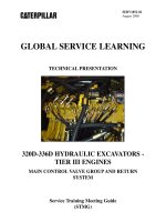
SERV1852-02
August 2008
GLOBAL SERVICE LEARNING
TECHNICAL PRESENTATION
320D-336D HYDRAULIC EXCAVATORS TIER III ENGINES
BOOM, STICK, AND BUCKET CIRCUITS
Service Training Meeting Guide
(STMG)
320D-336D HYDRAULIC EXCAVATORS TIER III ENGINES
BOOM, STICK, AND BUCKET CIRCUITS
AUDIENCE
Level II - Service personnel who understand the principles of machine systems operation,
diagnostic equipment, and procedures for testing and adjusting.
CONTENT
This presentation provides an introduction and describes the components and systems operation
of the 320D-336D implement circuits - boom, stick, and bucket. Additional presentations will
cover the machine walkaround, engines, pilot system, main control valve group, implements,
swing system, travel system, and tool control systems in more detail. This presentation may be
used for self-paced and self-directed training.
OBJECTIVES
After learning the information in this presentation, the technician will be able to:
1. identify the correct operation of the boom, stick, and bucket on the 320D-336D hydraulic
excavators, and
2. diagnose problems in the boom, stick, and bucket circuits.
REFERENCES
320D Hydraulic Excavator Specalog
323D L and 323D LN Hydraulic Excavators
324D Hydraulic Excavator Specalog
325D Hydraulic Excavator Specalog
328D Hydraulic Excavator Specalog
330D Hydraulic Excavator Specalog
Machine Monitoring System - Systems Operation
Self-study "300D Series Hydraulic Excavators, 345C Hydraulic Excavator,
and 365C & 385C Large Hydraulic Excavators
iTIM " '300C' Series Hydraulic Excavators-Electronic Control Systems"
iTIM "325C Hydraulic Excavators-Hydraulic Systems"
325D Hydraulic Schematic
Estimated Time: 1 1/2 Hours
Illustrations: 44
Form: SERV1852-02
Date: August 2008
© 2008 Caterpillar
AEHQ5856
HEHH3327
AEHQ5663
AEHQ5665
AEHQ5706
AEHQ5667
RENR8068
SERV7032
SERV2693
SERV2701
KENR6157
SERV1852-02
08/08
-3-
Text Reference
Implements
TABLE OF CONTENTS
INTRODUCTION ........................................................................................................................5
Boom Circuit...........................................................................................................................8
Stick Circuit .........................................................................................................................34
Bucket Circuit .......................................................................................................................52
Cylinders ...............................................................................................................................53
CONCLUSION ..........................................................................................................................55
SERV1852-02
08/08
-4-
Text Reference
Implements
PREREQUISITES
"Fundamentals of Mobile Hydraulics Self Study Course"
"Fundamentals of Power Train Self Study Course"
"Fundamentals of Electrical Systems Self Study Course"
"Fundamentals of Engines Self Study Course"
TEMV3002
TEMV3003
TEMV3004
TEMV3001
NOTES
Nomenclature Change: During the fourth quarter of 2008, the 325D and 330D
nomenclature changed. The 325D became the 329D and the 330D became the 336D for
most arrangements.
The exceptions are as follows:
- The nomenclature for the 325D MH and 330D MH did not change.
- The nomenclature for the 325D FM and 330D FM did not change.
- The 325D HD HW did not change into 329D HD HW. This model is being discontinued.
However, the 330D HD HW changed to the 336D HD HW.
SERV1852-02
08/08
-5-
Text Reference
Implements
IMPLEMENT CIRCUITS
Stick Cylinder
Bucket Cylinder
Swing Motor
Main Control Valve Group
Pilot
Control
Valves
Priority
Valves
Pilot Manifold
Pilot
Pump
Fan
Motor
Boom Cylinders
Travel Motors
Main
Hydraulic
Pumps
M
Fan
Pump
Tank
The Fan Motor and Pump are only used on the 330D and 336D
1
INTRODUCTION
This presentation covers in more detail each implement circuit used for the 320D-336D
Hydraulic Excavators. The circuits to be covered include:
- boom
- stick
- bucket
The idler pump provides oil to the boom 2 and stick 1 control valves. The drive pump provides
flow to the bucket, boom 1, and stick 2 control valves.
The boom, stick, and bucket control valves are shifted by pilot oil from the joystick pilot valves
when they are activated.
NOTE: The main control valve group and return system are covered in another
presentation. The attachment/auxiliary circuits will be covered in the electronic or tool
control section. The ISO schematics were created primarily from "325D Hydraulic
Schematic" (KENR6157). Hydraulic schematics for other 320D-336D excavators
may/will have variations from illustrations shown.
SERV1852-02
08/08
-6-
Text Reference
Implements
3
4
1
5
2
2
The boom circuit uses two control valves to control the boom operation, boom 1 (1) and boom
2 (2). Both spools shift when fast boom movement is required. Both pumps provide flow to
the boom for this condition. Boom 1 valve provides single pump flow, whenever the boom is
shifted for slow movement.
The stick circuit also uses to two control valves to control the stick operation, stick 1 (3) and
stick 2 (4). Both spools shift when fast stick movement is required.
The boom circuit and stick circuits also use regeneration valves and drift reduction valves. The
regeneration valves (not shown) provide improved efficiency and require less engine
horsepower for BOOM LOWER and STICK IN.
The drift reduction valves reduce cylinder drift when the boom or stick are in NEUTRAL.
Only one control valve is required to control the bucket. The bucket circuit is supplied with oil
only from the drive pump.
SERV1852-02
08/08
-7-
Text Reference
Implements
1
2
3
The two joysticks in the cab are used to control the movements of the boom, stick, swing and
bucket circuits.
- right joystick (1) to control the bucket and boom (SAE excavator pattern)
- left joystick (2) to control the swing and stick (SAE excavator pattern)
SERV1852-02
08/08
-8-
Text Reference
Implements
MAIN HYDRAULIC SYSTEM
Boom
Cylinders
BOOM CIRCUIT COMPONENTS
Drift
Reduction
Valve
Boom 2
Boom 1
NFC
Orifice
Main
Relief
Boom Regen
Valve
Swing / Stick
Pilot Valve
Heavy Lift
Solenoid
Boom / Bucket
Pilot Valve
Idler Pump
Pilot Pump
M
Drive Pump
Boom
Priority
Valve
AEC Pressure
Switch
Pilot Manifold
4
Boom Circuit
The boom circuit consists of the following major components:
- boom 1 spool
- boom 2 spool
- two boom cylinders
- drift reduction valve
- Heavy Lift solenoid
- boom priority valve (pressure reducing)
- boom lowering control valves (if equipped - not shown))
- boom regeneration valve
- SmartBoom™ (if equipped - not shown))
NOTE: 325D Hydraulic Schematic (KENR6157) was used to develop the ISO
schematics.
SERV1852-02
08/08
-9-
Text Reference
Implements
Boom 1 Spool: The boom 1 spool controls oil flow from the drive pump. The boom 1 spool
receives a BOOM RAISE pilot signal on the bottom of the valve, and a BOOM LOWER pilot
signal on the top of the valve.
Boom 2 Spool: The boom 2 spool controls oil flow from the idler pump. The boom 2 spool
receives a BOOM RAISE pilot signal from the joystick on the top of the valve stem, when
active. The boom 2 spool does not operate during BOOM LOWER. The boom 2 spool has no
provisions for return oil from the boom cylinders.
Boom Cylinders: The boom cylinders work in parallel to control the raise and lower
movement of the boom. When oil is supplied to the head end of the boom cylinders, the boom
will raise. When oil is supplied to the rod end of the boom cylinders, the boom will lower.
Boom Drift Reduction Valve: The boom drift reduction valve prevents oil from leaking from
the head end of the boom cylinders. For BOOM LOWER, pilot oil from the joystick is used to
unlock the lock check valve in the drift reduction valve.
Heavy Lift Solenoid: The heavy lift solenoid is activated to increase the maximum system
pressure for lifting. (Refer to the "Main Control Valve Group and Return Group" for more
details on Heavy Lift operation.)
Boom Priority Valve: The boom priority valve (pressure reducing) is used to reduce the pilot
pressure to the stick 2 valve whenever both the BOOM RAISE and STICK IN are activated at
the same time. The higher the boom pilot pressure to the boom priority valve the less pilot
pressure is available to shift the stick 2 control valve, resulting in more pump flow going to the
boom cylinders.
Boom Lowering Control Valves: The boom lowering control valves are infinitely variable,
pilot operated control valves that control the movement of the boom during lowering. The
boom lowering control valves prevent boom cylinder drift with valving mounted directly on
each of the boom cylinders, that controls boom cylinder head end oil flow.
Because the valves are mounted directly to each of the boom cylinders, the boom lowering
control valves will prevent the boom from falling, even if a hose becomes defective from the
main control valve to the cylinders.
The boom lowering control valves also work in conjunction with the SmartBoom™ system to
control the boom with the function active.
Regeneration Valve: The regeneration valve allows return oil from the head end of the boom
cylinders to be directed into the rod end of the cylinders when the boom is lowered fast.
SmartBoom™: The SmartBoom™ attachment enhances operation of the boom function and
significantly reduces cycle times of the machine. The SmartBoom™ is essentially a boom float
attachment, which allows the operator to lower the boom under its own weight or for the boom
to raise up due to stick force. The SmartBoom™ attachment is typically used in EAME.
SERV1852-02
08/08
- 10 -
Port A
Text Reference
Implements
Port B
Load
Check
Valve
CONTROL VALVE
NEUTRAL
Line Relief
and Makeup
Valve
Pilot
Valve
Pilot
Valve
Parallel
Feeder
Passage
Center
Bypass
Passage
Control
Spool
5
As previously discussed, the control valve operation is similar for all of the valves in the main
control valve group including the boom, stick, and bucket valves. Pump flow is provided by
the drive and/or idler hydraulic pump. Which pump is used depends on the circuit.
The centering spring force holds the valve spool to NEUTRAL when there is no pilot oil
pressure directed to shift the spool.
In NEUTRAL the valve spool allows oil to flow unrestricted through the center bypass passage,
which directs a high NFC pressure signal to the pump control valve. The high NFC pressure
causes the pump to destroke to a standby condition, as explained previously.
SERV1852-02
08/08
- 11 -
Text Reference
Implements
MAIN HYDRAULIC SYSTEM
BOOM RAISE - SLOW SPEED
Drift
Reduction
Valve
Boom 2
Stick 2
Boom 1
NFC
Orifice
Main
Relief
Boom Regen
Valve
Swing / Stick
Pilot Valve
Boom / Bucket
Pilot Valve
Heavy Lift
Solenoid
Swing
Priority
Valve
NFC
Orifice
Idler Pump
Pilot Pump
M
Drive Pump
Boom
Priority
Valve
AEC Pressure
Switch
Pilot Manifold
6
When the boom joystick is moved less than half of the travel distance for BOOM RAISE, low
pilot oil pressure is supplied to the boom 1 control valve and the boom 2 control valve.
The force of the centering spring in the boom 1 control valve is less than the force of the
centering spring in the boom 2 control valve. When the boom is raised at a low speed, the
boom 1 control valve opens and the boom 2 control valve remains closed due to the low pilot
pressure.
The drive pump supply oil flows past the boom 1 control valve and unseats the check valve in
the drift reduction valve and flows to the head end of the boom cylinders.
Return oil from the rod end of the boom cylinders returns back to the tank through the boom 1
control valve.
With the boom valve partially shifted less oil is directed to the NFC relief valve. Less oil to the
NFC relief valve results in a reduced NFC signal to the drive pump. The drive pump control
valve causes the pump to upstroke to provide flow to operate the boom.
A BOOM RAISE operation at low speed is accomplished when only the drive pump is supplied
to the head end of the boom cylinders.
SERV1852-02
08/08
- 12 -
Text Reference
Implements
BOOM 1 CONTROL VALVE
BOOM RAISE PARTIAL SHIFT
Boom
Head End
Boom
Rod End
NFC Signal
Load
Check Valve
Parallel
Feeder
Passage
Joystick
Center
Bypass
Passage
Boom
Regen Valve
7
When the operator begins to move the joystick to shift the boom 1 control valve, metered pilot
pressure causes the control valve to shift slightly.
With the spool initially shifted, the center bypass passage is partially closed. This movement
causes NFC pressure to decrease, which signals the drive pump to begin to upstroke.
The load check valve prevents unexpected implement movements when a joystick is initially
activated at a low pump delivery pressure. The load check valve also prevents oil loss from a
high pressure circuit to a lower pressure circuit.
As the pump supply pressure increases, the load check valve opens to allow pump supply oil in
the parallel feeder passage to flow to the control spool.
The control spool meters pump supply oil to the head ends of the boom cylinders.
SERV1852-02
08/08
- 13 -
Text Reference
Implements
MAIN HYDRAULIC SYSTEM
BOOM RAISE - FAST SPEED
Drift
Reduction
Valve
Boom 2
Boom 1
NFC
Orifice
Main
Relief
Boom Regen
Valve
Swing / Stick
Pilot Valve
Boom / Bucket
Pilot Valve
Heavy Lift
Solenoid
Swing
Priority
Valve
Idler Pump
Pilot Pump
M
Drive Pump
Boom
Priority
Valve
AEC Pressure
Switch
Pilot Manifold
8
A BOOM RAISE operation at high speed is accomplished when supply oil from both the idler
pump and the drive pump is supplied to the head end of the boom cylinders.
Boom 1 control valve and boom 2 control valve are both shifted during high speed operation.
SERV1852-02
08/08
- 14 -
Text Reference
Implements
BOOM 1 CONTROL VALVE
BOOM RAISE FULL SHIFT
Load
Check Valve
Boom
Rod End
Boom
Head End
NFC Signal
Parallel
Feeder
Passage
Joystick
Boom
Regen Valve
Center
Bypass
Passage
9
As the operator moves the joystick farther, the pilot pressure on the end of the spool increases.
The increased pilot pressure causes the boom 1 spool to shift further to the right.
The center bypass passage is now closed, which blocks the oil flow to the NFC signal port on
the right pump control valve. When the NFC signal is reduced, the pump upstrokes and flow is
increased. The increased flow can no longer return to tank through the center bypass passage.
All oil now flows through the parallel feeder path.
The increased oil flow to the parallel feeder passage causes pressure to rise in the parallel
feeder passage. The increased oil pressure overcomes the force of the load check spring and
the boom head end pressure, which causes the load check valve to unseat. Oil flows out to
boom cylinders.
The oil returning from the rod end of the cylinders flows past the spool and returns to tank.
SERV1852-02
08/08
- 15 -
Variable Swing
Priority Valve
Text Reference
Implements
BOOM 2 CONTROL VALVE
FAST BOOM RAISE
Swing Priority
Pressure
Reducing Valve
Boom Cylinder
Head End
Parallel Feeder
Passage
Load Check
Valve
Center Bypass
Passage
Control Spool
10
The pilot oil flow shifts the boom 2 control valve. The idler pump supply oil in the parallel
feeder passage flows past the check valve and flows out to the head end of the boom cylinders.
The idler pump supply oil combines with the drive pump supply oil at the boom drift reduction
valve (not shown) and flows to the head end of boom cylinders.
Return oil from the rod end of boom cylinders flows to the boom 1 control valve and then to
the tank. The boom 2 control valve does not handle any of the return flow for the boom circuit.
NOTE: The swing priority valve does not affect the operation of the boom 2 control
valve.
SERV1852-02
08/08
- 16 -
Text Reference
Implements
MAIN HYDRAULIC SYSTEM
BOOM PRIORITY - BOOM RAISE AND STICK IN
Drift
Reduction
Valve
Stick Regen
Valve
Boom 2
Stick 2
Boom 1
Stick 1
NFC
Orifice
Main
Relief
Boom Regen
Valve
Stick Unloading
Valve
Swing / Stick
Pilot Valve
Boom / Bucket
Pilot Valve
Heavy Lift
Solenoid
Swing
Priority
Valve
Idler Pump
Pilot Pump
M
Drive Pump
Boom
Priority
Valve
AEC Pressure
Switch
Pilot Manifold
11
During combined operations of BOOM RAISE and STICK IN, the boom raise pilot oil pressure
shifts the pressure reducing valve for the boom priority valve to reduce the stick in pilot
pressure for the stick 2 control valve. With the reduction in stick in pilot pressure to the stick 2
control valve, more pump flow is directed to the boom cylinders during this combined
hydraulic operation.
NOTE: For STICK IN, the stick circuit regeneration valve will shift to direct return oil
from the rod end of the stick cylinder to the head end of the cylinders.
When the joystick for the stick is moved to the STICK IN position, a portion of the pilot oil
from the pilot control valve for the stick flows through the pressure reducing valve for the
boom priority to the stick 2 control valve. As the joystick for the boom is moved farther for a
BOOM RAISE, pilot oil pressure from the pilot control valve for the boom increases. This
gradual increase in pilot oil pressure causes the spool in the pressure reducing valve for the
boom priority to gradually shift.
A portion of the pilot oil to the stick 2 control valve from the stick pilot control valve is
restricted by the boom priority valve. The pilot oil pressure acting on the stick 2 control valve
decreases.
SERV1852-02
08/08
- 17 -
Text Reference
Implements
The stick 2 control valve shifts toward the NEUTRAL position. The amount of oil flow from
the main pumps to the stick hydraulic circuit decreases. This change causes a greater portion of
the oil flow from the main pumps to flow to the head end of the boom cylinders.
Since the pilot oil pressure from the boom pilot control valve directly corresponds to the
amount of movement or position of the boom joystick a gradual change to boom priority
occurs.
Thus, boom priority is controlled by the position of the joystick for the boom and boom priority
automatically activates when the joystick reaches a certain position during a BOOM RAISE
operation.
The above information describes the condition of BOOM RAISE and STICK IN. During any
combined function of BOOM RAISE and STICK IN, the pressure reducing valve for boom
priority reduces pilot pressure to the stick 2 control valve.
NOTE: If the joysticks are fully shifted for BOOM RAISE and STICK IN, stick in pilot
pressure on the bottom of the boom 2 cancels the boom raise pilot pressure on top of the
boom 2 spool. At the same time the boom priority valve prevents stick in pilot pressure
from going to the stick 2 control valve.
These two actions result in the drive pump supplying oil to the boom cylinders and the
idler pump providing oil to the stick cylinder.
SERV1852-02
08/08
- 18 -
Text Reference
Implements
MAIN HYDRAULIC SYSTEM
BOOM LOWER WITH REGENERATION
Drift
Reduction
Valve
Boom 2
Boom 1
NFC
Orifice
Main
Relief
Boom Regen
Valve
Swing / Stick
Pilot Valve
Boom / Bucket
Pilot Valve
Heavy Lift
Solenoid
Swing
Priority
Valve
Idler Pump
Pilot Pump
M
Drive Pump
Boom
Priority
Valve
AEC Pressure
Switch
Pilot Manifold
12
For BOOM LOWER only the boom 1 control valve is used. The drive pump partially strokes
to provide flow to the rod end of the boom cylinders.
When the joystick is shifted pilot oil moves the boom 1 control spool down, the regeneration
valve right, and unlocks the drift reduction valve. When the boom 1 control spool is fully
shifted, the center bypass valve is never fully closed off. By not closing off the center passage,
there is an NFC signal to the drive pump. The drive pump never fully upstrokes.
Due to the force of gravity, with the lock valve unlocked, the weight of the boom and the load
on the boom, force the return oil out of the cylinder head ends back to the regeneration valve
and the boom 1 control valve.
The boom 1 control valve restricts the return oil flow. Whenever the return oil pressure is
higher than the supply pressure in the rod end of the cylinders, the return oil from the boom
cylinder head ends unseats the check valve above the regeneration valve.
The return oil from the head end enters the supply passage to the rod end to help fill the
cylinders and prevent cylinder cavitation. The regeneration valve allows the excavator to
operate more efficiently. The main pump supply oil not required to lower the boom is available
to operate another circuit.
SERV1852-02
08/08
- 19 -
Text Reference
Implements
BOOM 1 CONTROL VALVE
BOOM LOWER
Load Check
Valve
Rod End
Head End
NFC Signal
Parallel
Feeder
Passage
Center
Bypass
Passage
Boom
Regen Valve
13
The boom pilot oil flow from shifts the boom control spool to the left against the force of the
centering spring. Supply oil from the drive pump in the parallel feeder passage flows past the
load check valve to the rod end of the boom cylinders.
Some of the oil in the center bypass passage flows past the center land to provide a reduced
NFC signal. The reduced NFC signal causes the drive pump to only partially upstroke.
Part of the return oil from the head end of boom cylinders flows to the boom drift reduction
valve.
SERV1852-02
08/08
- 20 -
Low Boom Down
Pilot Pressure
Text Reference
Implements
BOOM REGENERATION VALVE
SLOW BOOM DOWN
Check
Valve
From Boom
Spool
A
A
To Boom
Spool
Regen Spool
A-A
14
The boom regeneration valve has two components, the boom regeneration valve itself and the
check valve.
During a slow BOOM DOWN, the low pilot pressure is not able to move the regeneration valve
down so return oil from the the boom cylinder head ends is not able to flow to the boom
cylinder rod ends.
SERV1852-02
08/08
- 21 -
High Boom Down
Pilot Pressure
Text Reference
Implements
BOOM REGENERATION VALVE
FAST BOOM DOWN
Check
Valve
From Boom
Spool
A
A
To Boom
Spool
Regen Spool
A-A
15
When boom lower pilot pressure increases, the boom regeneration valve is pushed down, a
passage is opened allowing boom head end oil to flow to the check valve. If the boom rod end
pressure is lower than the boom head end oil pressure, then the check valve opens allowing
boom head end oil to be directed to the boom rod end.
The check valve closes if the boom rod end oil pressure is higher than the boom head end oil
pressure, such as when the boom is being powered down.
SERV1852-02
08/08
- 22 -
Text Reference
Implements
BOOM DRIFT REDUCTION VALVE
BOOM RAISE
Manual Bleed
Valve
Line Relief
Valve
Check Valve
B
B
Boom 2
Shuttle
Valve
Boom 1
A-A
From Boom 1
And Boom 2
Control Valves
Lock Check
Valve
To Boom Cylinders
Head End
Shuttle Valve
A
A
Line Relief Valve
Line Relief
Valve
Shuttle
Valve
B-B
16
Boom Drift Reduction Valve: The boom drift reduction valve prevents oil from leaking from
the head end of the boom cylinders. The boom drift reduction valve is located on the main
control valve group. The boom drift reduction valve has the following components:
- shuttle valve
- lock check valve
- line relief valve
In NEUTRAL, the shuttle valve and check valve are closed by spring force. Oil is blocked
between the boom control valve and the boom cylinders.
For BOOM RAISE, the shuttle valve is closed by spring force. When closed, the shuttle valve
allows oil from the boom control valves to act on one end of the lock check valve.
Oil pressure from the boom control valves acts on the other end of the lock check valve. The
lock check valve opens (due to pressure differential on check valve) to allow oil flow to the rod
end of the boom cylinders.
SERV1852-02
08/08
- 23 -
Text Reference
Implements
BOOM DRIFT REDUCTION VALVE
BOOM LOWER
Manual Bleed
Valve
Line Relief
Valve
Check Valve
Boom 2
B
B
To Tank
Shuttle
Valve
Boom 1
To Boom 1
Control Valve
From Boom Cylinders
Head End
Check
Valve
Shuttle Valve
A
A
Line Relief
Valve
Line Relief Valve
Shuttle
Valve
B-B
17
For BOOM LOWER, the shuttle valve is opened by pilot oil from the joystick. The shuttle
valve allows oil from the spring end of the lock check valve to return to tank.
Oil pressure from the boom cylinder head end opens the lock check valve. The lock check
valve allows oil flow from the head end of the boom cylinders to return to the boom control
valve.
SERV1852-02
08/08
- 24 -
Text Reference
Implements
4
5
3
1
2
6
18
Boom Lowering Control Valves: The boom lowering control valves (1 and 2) are mounted on
the head end of the boom cylinders. If the machines are equipped with the optional boom
lowering valves, the drift reduction valve for the boom is not installed on the machine.
The boom lowering control valves serve several purposes:
- prevent the boom from falling rapidly in case of hose failure
- provide BOOM LOWER control with SmartBoom™ (if equipped) activated
- prevent boom drift
The lowering control valves are equipped with head end line relief valves (3) to protect the
cylinders from sudden shocks.
A pilot line (4) directs pilot oil to unlock the lowering control valve so the boom can be
lowered.
The tube (5) provides supply oil from the boom control valve.
A hose (6) connects both lowering control valves. The line provides for equalization of
pressures in the head end of the cylinders when the boom is raised or lowered to provide
smooth movement.
SERV1852-02
08/08
- 25 -
Text Reference
Implements
Boom
Down Pilot
BOOM LOWERING CONTROL VALVE
NEUTRAL
Boom Cylinder Head End
Line Relief Valve
Boom Control
Valve
Tank
Check Valve
Boom Lowering
Control Valve
Equalization
Passage
Boom Control
Valve
Opposite
Cylinder
Manual
Lower
Boom
Down Pilot
Orifice
Boom Control
Valve
Opposite
Cylinder
Head End
19
When the boom circuit is equipped with boom lowering control valves (or load control valves),
the lowering control valves are attached directly to each of the boom cylinders.
The following major components are used in the boom lowering control valves :
- boom head end line relief
- check valve
- boom lowering control valve spool
- orifice
- manual lower