10 FBD programming i
Bạn đang xem bản rút gọn của tài liệu. Xem và tải ngay bản đầy đủ của tài liệu tại đây (505.96 KB, 33 trang )
DAY 3
SESSION 2
FUNCTION BLOCK DIAGRAM (FBD)
PROGRAMMING I
6 – 10 December 2010
ADD PFD ROUTINE
1. Right Click on main
program and choose New
Routine
2. Write New Routine
name and choose
Function Block Diagram
for its type
3. Open the new routine
6 – 10 December 2010
CREATE TAGS
1. Right Click on Program
Tags and choose New
Tag
2. Write a name, select
data type, scope, and
style for the tag
6 – 10 December 2010
ADD A SHEET IN ROUTINE
1
1. Click the icon
2
2. Type a sheet description
6 – 10 December 2010
FUNCTION BLOCK DATA FLOWS
6 – 10 December 2010
FUNCTION BLOCK ELEMENT
6 – 10 December 2010
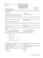
LATCHING DATA
=
The Input Reference value does not change
until the next scan execution of the routine
6 – 10 December 2010
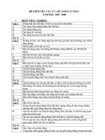
FUNCTION BLOCK INSTRUCTION
BAR
Navigation button
of FB Instruction
Navigation button
of Element Group
Navigation button
IO Instruction
of FB Instruction
FB Instruction
Element Group
6 – 10 December 2010
ADD INSTRUCTION TO SHEET
1. Select
2. Drag
3. Drop
6 – 10 December 2010
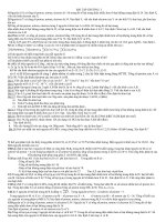
CONNECT ELEMENT(1)
1.
Show or Hide a Pin
TONR_01
TONR
...
Timer On Delay with Reset
0
TimerEnable
1. Click button to show
the block properties
ACC
0
PRE
Reset
DN
2. Check to show the
pin, and Uncheck to hide
the pin
6 – 10 December 2010
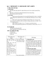
EXAMPLE OF SHOWING A PIN
SCL_01
SCL
Scale
SCL_01
SCL
...
0.0
...
In
Out
0
Scale
MaxAlarm
InRawMin
MinAlarm
0
0.0
In
InRawMax
Out
Check the Vis Pin
InEUMax
InEUMin
Limiting
Check the Vis Pin
I for Input
O for Output
6 – 10 December 2010
CONNECT ELEMENT(1)
1.
Show or Hide a Pin
TONR_01
TONR
1. Click button to show the
block properties
...
Timer On Delay with Reset
0
TimerEnable
ACC
0
PRE
Reset
DN
2. Check to show the pin, and
Uncheck to hide the pin
6 – 10 December 2010
CONNECT ELEMENT(2)
2. Wire Element Together
A
B
Green Dots
•
Click Output pin of the First element (A)
•
Then Click input pin of the other element (B)
•
Green Dots show a valid connection point
6 – 10 December 2010
CONNECT ELEMENT(3)
3. Assume Data Available
Resolve a loop
TONR_04
TONR_03
TONR
TONR
...
Timer On Delay with Reset
0
BOOLEAN_1
TimerEnable
PRE
Timer On Delay with Reset
0
TimerEnable
0
LOOP
PRE
0
ERRORReset
DN
ACC
...
ACC
0
DN
Reset
If a group of blocks are in a loop, the controller cannot determine
which block to execute first. In other words, it cannot resolve the loop.
6 – 10 December 2010
ASSUME DATA AVAILABLE
To define a wire as an input, right-click the wire and choose
Assume Data Available.
TONR_04
TONR_03
TONR
TONR
...
Timer On Delay with Reset
0
Timer On Delay with Reset
0
BOOLEAN_1
...
TimerEnable
ACC
0
TimerEnable
ACC
0
PRE
DN
0
PRE
DN
Reset
Reset
This input pin uses the output that block 2 produced on the
previous scan.
6 – 10 December 2010
TOGGLE BIT
Example:
Toggle Switch_0
1. Right Click on IO Block
Instruction, choose
Monitor “Switch_0”
2. Program Tag Window
Shown
3. Right Click on the tag,
choose Toggle bit
6 – 10 December 2010
MONITOR VALUE
1. From FBD Window
2. From Program Tag
Window
ALM_04
ALM
...
Alarm
0
In
HHAlarm
0
HAlarm
0
LAlarm
0
LLAlarm
0
ROCPosAlarm
0
ROCNegAlarm
6 – 10 December 2010
FUNCTION BLOCK
INSTRUCTION
6 – 10 December 2010
A. IO REFERENCE & IO WIRING
CONNECTION
IO Reference :
2#0000_0000
In_Ref_test
Out_Ref_test
Tagname
IO Wiring Connection :
LES_01
LES
...
Less Than (A
A
0
SourceA
1-C3
Dest
SourceB
B
1-A3
100
100
Any name, use to connect
programs in different sheets
in a subroutine
6 – 10 December 2010
B. PROCESS INSTRUCTION (1)
1. Alarm
ALM_01
Device Tagname
ALM
0
...
Alarm
LV001
0
In
HHAlarm
90
0
90
HHLimit
HAlarm
HLimit
LAlarm
LLimit
LLAlarm
70
70
0
0
30
30
0
LLLimit
ROCPosAlarm
Deadband
ROCNegAlarm
10
10
Alarm Limit Value
0
Alarm Status
6 – 10 December 2010
B. PROCESS INSTRUCTION (2)
2. SCL
Device Tagname (Raw
Data)
SCL_01
SCL
0
Device Tagname
(Scale Data)
...
Scale
LV001
0.0
In
Out
LV001_SCL
4096
4096
InRawMax
0
0
InRawMin
InEUMax
100
100
InEUMin
0
0
Limiting
1
1
If set, Output is limited to
between InEUMin and InEUMax.
6 – 10 December 2010
C. SELECT INSTRUCTION
SEL (Select)
SEL_01
SEL
...
Select
0
0.0
LV001
In1
Out
LV001_VAL
0
0
In2
0
LALL001
SelectorIn
If SelectorIn is set Output = In2
If SelectorIn is clear Output = In1
Input1
Input2
Selector
Output
6 – 10 December 2010
D. BIT INSTRUCTION
1. OSRI (One Shot Rise with Input)
2. OSFI (One Shot Falling with Input)
6 – 10 December 2010
E. TIMER/COUNTER INSTRUCTION
(1)
1. TONR (Timer On Delay With Reset)
TONR_01
TONR
...
Timer On Delay with Reset
0
PULSE1_ALARM
0
TimerEnable
ACC
0
PRE
DN
HORN
1000
1000
Reset
0
RESET_ALARM
Each scan that TimerEnable is set, the TONR instruction
increments the ACC value until the ACC value reaches the PRE
value. When ACC = PRE, the DN parameter is set
6 – 10 December 2010
E. TIMER/COUNTER INSTRUCTION
(2)
2. CTUD (Counter Up/Down)h
CTUD_01
0
CTUD
...
LALL001
Count Up/Down
0
CUEnable
ACC
CDEnable
DN
1000
0
1000
HORN
PRE
0
RESET_ALARM
Reset
CUEnable
Reset
Preset
ACC
DN
6 – 10 December 2010