Chi tiết cấu tạo và bản vẽ chi tiết Nokia 6085
Bạn đang xem bản rút gọn của tài liệu. Xem và tải ngay bản đầy đủ của tài liệu tại đây (5.37 MB, 46 trang )
Page
CMO Operations & Logistics
Training and Vendor Development
Multimedia Creation & Support
1 (46)
Approved 10.0
MGR
15.Oct.2007
CONFIDENTIAL
SERVICE MANUAL
Level 1&2
RM-198
RM-260
RM-188
Transceiver characteristics:
Band: Quad-band GSM/EDGE phone 850/900/1800/1900MHz
Camera: VGA camera with 4x digital post zoom
Display:
- Main display: 128 x 160-pixel, 1.8” CSTN passive LCD with
262,144 colors
- Cover display: 96 x 68-pixel, FSTN, black/ white with blue LEDs
Bluetooth
FM stereo radio
Connector: Pop-Port™ Connector
Memory: microSD™
Transceiver with BL-5C Li-Ion battery pack
Talk time
Standby
Note
up to 5h
up to 10days
Depends on network
parameters
Environmental characteristics:
•
Service Manual 6085 RM-198 / 6086 RM-188/RM-260
Lead-freesoldered
Copyright © 2006-2007 NOKIA Corporation. All rights reserved.
Page
CMO Operations & Logistics
Training and Vendor Development
Multimedia Creation & Support
2 (46)
Approved 10.0
MGR
15.Oct.2007
CONFIDENTIAL
TABLE OF CONTENTS
1.
2.
3.
4.
5.
6.
7.
8.
9.
10.
11.
12.
13.
14.
15.
16.
17.
18.
19.
20.
21.
22.
23.
24.
25.
26.
Page
INTRODUCTION
EXPLODED VIEW
SPARE PARTS OVERVIEW
LEVEL 2 SOLDER COMPONENTS
SERVICE DEVICES
SW-UPDATE
UPPER BLOCK DISASSEMBLY
UPPER BLOCK ASSEMBLY
LOWER BLOCK DISASSEMBLY
LOWER BLOCK ASSEMBLY
LEGEND FOR QUICK TROUBLE SHOOTER
QUICK TROUBLE SHOOTER - POWER ON
QUICK TROUBLE SHOOTER - CHARGING
QUICK TROUBLE SHOOTER - NO SERVICE
QUICK TROUBLE SHOOTER - SIM
QUICK TROUBLE SHOOTER - EARPIECE
QUICK TROUBLE SHOOTER - IHF SPEAKER
QUICK TROUBLE SHOOTER - DISPLAY SMALL
QUICK TROUBLE SHOOTER - DISPLAY
QUICK TROUBLE SHOOTER - MICROPHONE
QUICK TROUBLE SHOOTER - KEYMAT
QUICK TROUBLE SHOOTER - VIBRA
QUICK TROUBLE SHOOTER - VOLUME KEYS
QUICK TROUBLE SHOOTER - CAMERA KEY
QUICK TROUBLE SHOOTER - MEMORY CARD READER
QUICK TROUBLE SHOOTER - CAMERA
3
4
5
6
7
9
10
15
23
27
31
32
33
34
35
36
37
38
39
40
41
42
43
44
45
46
CHANGE HISTORY
Status
Version No.
Date
Comments
Draft
0.1
09.OKT.2006
Initialdraft
Approved
1.0
23.Okt.2006
Approval
Approved
2.0
24.Okt.2006
SS-6 added to the Tools chapter
Approved
3.0
25.Okt.2006
Spare Parts overview added
Approved
4.0
22.Nov.2006
6086 RM-188 added
Approved
5.0
21.Feb.2007
Exploded view & Spare Parts overview update; General Recycling
recommendation added
Approved
6.0
14.Mrz.2007
Exploded view & Spare Parts overview update, Page Battery Test and
GONOGO Test removed
Approved
7.0
20.Mrz.2007
RM-260 added
Approved
8.0
29.May.2007
Exploded view & Spare Parts overview update
Approved
9.0
28.Sept.2007
Exploded view & Spare Parts overview update
Approved
10.0
15.Oct.2007
Exploded view & Spare Parts overview update
Service Manual 6085 RM-198 / 6086 RM-188/RM-260
Copyright © 2006-2007 NOKIA Corporation. All rights reserved.
Page
CMO Operations & Logistics
Training and Vendor Development
Multimedia Creation & Support
3 (46)
Approved 10.0
MGR
CONFIDENTIAL
15.Oct.2007
1. INTRODUCTION
ThepurposeofthisdocumentistohelpNOKIAservicelevels1and2workshoptechnicianstocarryoutserviceto
NOKIAproducts.ThisServiceManualistobeusedonlybyauthorizedNOKIAservicesuppliers,andthecontentofitis
confidential.PleasenotethatNOKIAprovidesalsootherguidancedocuments(e.g.ServiceBulletins)forservicesuppliers,followtheseregularlyandcomplywiththegiveninstructions.
Whileeveryendeavorhasbeenmadetoensuretheaccuracyofthisdocument,someerrorsmayexist.
Ifyoufindanyerrorsorifyouhavefurthersuggestions,pleasenotifyNOKIAusingtheaddressbelow:
mailto:
Pleasekeepinmindalsothatthisdocumentationiscontinuouslybeingupdatedandmodified,sowatchalwaysout
forthenewestversion.
Warnings and Cautions
Pleaserefertothephone’suserguideforinstructionsrelatingtooperation,careandmaintenanceincludingimportantsafetyinformation.Notealsothefollowing:
Warnings:
1.
2.
3.
CARE MUST BE TAKEN ON INSTALLATION IN VEHICLES FITTED WITH ELECTRONIC ENGINE MANAGEMENT SYSTEMS
AND ANTI–SKID BRAKING SYSTEMS. UNDER CERTAIN FAULT CONDITIONS, EMITTED RF ENERGY CAN AFFECT THEIR
OPERATION. IF NECESSARY, CONSULT THE VEHICLE DEALER/MANUFACTURER TO DETERMINE THE IMMUNITY OF VEHICLE ELECTRONIC SYSTEMS TO RF ENERGY.
THE HANDPORTABLE TELEPHONE MUST NOT BE OPERATED IN AREAS LIKELY TO CONTAIN POTENTIALLY EXPLOSIVE
ATMOSPHERES,EGPETROLSTATIONS(SERVICESTATIONS),BLASTINGAREASETC.
OPERATION OF ANY RADIO TRANSMITTING EQUIPMENT, INCLUDING CELLULAR TELEPHONES, MAY INTERFERE WITH
THE FUNCTIONALITY OF INADEQUATELY PROTECTED MEDICAL DEVICES. CONSULT A PHYSICIAN OR THE MANUFACTURER OF THE MEDICAL DEVICE IF YOU HAVE ANY QUESTIONS. OTHER ELECTRONIC EQUIPMENT MAY ALSO BE SUBJECT TO
INTERFERENCE.
Cautions:
1.Servicingandalignmentmustbeundertakenbyqualifiedpersonnelonly.
2. Ensure all work is carried out at an anti–static workstation and that an anti–static wrist strap is worn.
3.Useonlyapprovedcomponentsasspecifiedinthepartslist.
4.Ensureallcomponents,modulesscrewsandinsulatorsarecorrectlyre–fittedafterservicingandalignment.
5. Ensure all cables and wires are repositioned correctly.
Electrostaticdischargecaneasilydamagethesensitivecomponentsofelectronicproducts.
ThereforeeveryServiceSupplierhastotakecareofallprecautions,whicharementionedinthe
service level related “Service Partner Requirements”, available on NOKIA Online. Also see ESD
Protection Requirements in this Service Manual.
Service Manual 6085 RM-198 / 6086 RM-188/RM-260
Copyright © 2006-2007 NOKIA Corporation. All rights reserved.
Page
CMO Operations & Logistics
Training and Vendor Development
Multimedia Creation & Support
4 (46)
Approved 10.0
MGR
CONFIDENTIAL
15.Oct.2007
2. EXPLODED VIEW
See corresponding ITEM/CIRCUIT REF in the Spare Parts Service Bulletins on NOL.
Service Manual 6085 RM-198 / 6086 RM-188/RM-260
Copyright © 2006-2007 NOKIA Corporation. All rights reserved.
Page
CMO Operations & Logistics
Training and Vendor Development
Multimedia Creation & Support
5 (46)
Approved 10.0
MGR
CONFIDENTIAL
15.Oct.2007
3. SPARE PARTS OVERVIEW
Service Manual 6085 RM-198 / 6086 RM-188/RM-260
Copyright © 2006-2007 NOKIA Corporation. All rights reserved.
Page
CMO Operations & Logistics
Training and Vendor Development
Multimedia Creation & Support
6 (46)
Approved 10.0
MGR
CONFIDENTIAL
15.Oct.2007
4. LEVEL 2 SOLDER COMPONENTS
Service Manual 6085 RM-198 / 6086 RM-188/RM-260
Copyright © 2006-2007 NOKIA Corporation. All rights reserved.
Page
CMO Operations & Logistics
Training and Vendor Development
Multimedia Creation & Support
7 (46)
Approved 10.0
MGR
CONFIDENTIAL
15.Oct.2007
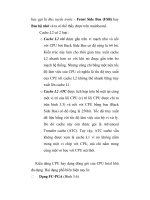
5. SERVICE DEVICES
FLS-4S incl. ACF-8, Driver and User Guide
Dongleandflashdeviceincorporatedintoonepackage,developedspecificallyforPOSuse.
ACF-8
Universal Power Supply is used to power FLS-4S.
Travel Charger AC-4
Smallandlightweightchargerforfastchargingofyourphone
battery.
Internal Battery BL-5C
Inserted under the back cover, this Li-Ion battery provides
power in a lightweight package.
SS-104
Domesheet & Display alignment jig
SS-88
Camera removal tool.
CA-53
Service Cable to connect the PC with the Pop-Port™ connector.
Service Manual 6085 RM-198 / 6086 RM-188/RM-260
Copyright © 2006-2007 NOKIA Corporation. All rights reserved.
Page
CMO Operations & Logistics
Training and Vendor Development
Multimedia Creation & Support
8 (46)
Approved 10.0
MGR
15.Oct.2007
CONFIDENTIAL
SS-6
Hinge opening tool.
RJ-154
Soldering Jig
Lead-free Solder Wire
Mandatoryforlead-freeproducts(Level2only).
0772040
NMP Standard Toolkit (V2)
FormoreinformationsrefertotheServiceBulletin(SB-011)on
NOKIA Online.
Supplierormanufacturercontactsfortoolre-ordercanbe
foundin“Recommended service equipment” document on
NOKIA Online.
Service Manual 6085 RM-198 / 6086 RM-188/RM-260
Copyright © 2006-2007 NOKIA Corporation. All rights reserved.
Page
CMO Operations & Logistics
Training and Vendor Development
Multimedia Creation & Support
9 (46)
Approved 10.0
MGR
CONFIDENTIAL
15.Oct.2007
6. SW-UPDATE
FlashConcept–(PointofSales)
TouseFLS-4SFlashDongleyouhavetofollowtheuserguideinsidethesalespackage.Pleasecheckalwaysforthe
latestversionofflashsoftware,whichisavailableon
NOKIA Online.
Service Manual 6085 RM-198 / 6086 RM-188/RM-260
Copyright © 2006-2007 NOKIA Corporation. All rights reserved.
Page 10 (46)
CMO Operations & Logistics
Training and Vendor Development
Multimedia Creation & Support
Approved 10.0
MGR
CONFIDENTIAL
15.Oct.2007
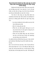
7. UPPER BLOCK DISASSEMBLY
1. Needed tools: SS-88 camera removal tool, the SS-6, the SS93, metal tweezers, a bit holder with a Torx Plus size 6 bit, a
torque driver...
2....andtheSS-104forittingtheadhesivesanddisplays.
3.Alwayscoverthewindowswithaprotectiveilm.
4.Removethebatteryifitisstillinserted.
5. Use the SS-93 to pry open the B-COVER UPPER ASSEMBLY,
starting at the top.
6. Release the clips shown, on both sides.
Service Manual 6085 RM-198 / 6086 RM-188/RM-260
Copyright © 2006-2007 NOKIA Corporation. All rights reserved.
Page 11 (46)
CMO Operations & Logistics
Training and Vendor Development
Multimedia Creation & Support
Approved 10.0
MGR
CONFIDENTIAL
7.ShifttheB-CoverAssytothehingedirectionandliftitup.
8.CovertheLCDPMwithaprotectiveilm.
9.CarefullyreleaseandremovetheCAMERAMODULEwiththe
SS-88 Camera removal tool.
10.Disconnectthelexconnector.
15.Oct.2007
11.CarefullyreleasetheadhesiveoftheLCDPMwiththeSS-93. 12. Remove the LCD PM.
Service Manual 6085 RM-198 / 6086 RM-188/RM-260
Copyright © 2006-2007 NOKIA Corporation. All rights reserved.
Page 12 (46)
CMO Operations & Logistics
Training and Vendor Development
Multimedia Creation & Support
Approved 10.0
MGR
CONFIDENTIAL
15.Oct.2007
13.Disconnectthelexconnector.
14. Fit the Torx Plus size 6 bit.
15.Unscrewthefourscrewsandremovethem.
16.LiftoutthePWB1WJ.
17.Covertheinnersidewindowwithaplasticilm.
18.CarefullyliftouttheEARPIECE.NotethattheSpeakerGasket
will be destroyed during the removal, and must be replaced
when reassemble.
Service Manual 6085 RM-198 / 6086 RM-188/RM-260
Copyright © 2006-2007 NOKIA Corporation. All rights reserved.
Page 13 (46)
CMO Operations & Logistics
Training and Vendor Development
Multimedia Creation & Support
MGR
CONFIDENTIAL
19.Coverthedisplaywithaplasticilm.
20.Releasethelexconnector.
21. Release the LCD BACK ADHESIVE with the SS-93.
22.CarefullyremovetheLCDCSDN.
23. Push out the glued in LCD WINDOW.
24.UnlocktheclipsoftheANTENNACAP.
Service Manual 6085 RM-198 / 6086 RM-188/RM-260
Approved 10.0
15.Oct.2007
Copyright © 2006-2007 NOKIA Corporation. All rights reserved.
Page 14 (46)
CMO Operations & Logistics
Training and Vendor Development
Multimedia Creation & Support
Approved 10.0
MGR
CONFIDENTIAL
15.Oct.2007
25. Remove the cap as shown.
26.BenddownthehingemodulewiththeSS-6irst.Notethat
the SS-6 is very delicate and can be break easily.
27. Now lock the HINGE with a torx bit size 6 or similar.
28. Now, the A-COVER UPPER ASSEMBLY can be removed easily.
Mindthelexfoil.TheHingecanbepulledoutafterthespring
expandingcarefullyifneeded.
29. The disassembly procedure is now completed.
Service Manual 6085 RM-198 / 6086 RM-188/RM-260
Copyright © 2006-2007 NOKIA Corporation. All rights reserved.
Page 15 (46)
CMO Operations & Logistics
Training and Vendor Development
Multimedia Creation & Support
Approved 10.0
MGR
CONFIDENTIAL
15.Oct.2007
8. UPPER BLOCK ASSEMBLY
1. Assembly
2.PlacetheA-COVERUPPERASSEMBLY.AfterlockingtheHINGEis
shown.
3.Mindthelexfoil.
4. Now expand the HINGE MODULE by removing the tool.
5.Ensurethatthehingeexpandscompletelybeforegoingon. 6. Place the ANTENNA CAP and click it into its place.
Service Manual 6085 RM-198 / 6086 RM-188/RM-260
Copyright © 2006-2007 NOKIA Corporation. All rights reserved.
Page 16 (46)
CMO Operations & Logistics
Training and Vendor Development
Multimedia Creation & Support
Approved 10.0
MGR
CONFIDENTIAL
15.Oct.2007
7.UsetheSS-104jigforpositioningthedisplaysandgasket
correctly.
8.Peeluptheprotectiveilmsfromthedisplays.
9. Place the displays into their compartments as shown.
10.FitnewgasketsonthePWB1WJforbothdisplays.
11.NowpositionthePWBtotheguidesofthejig.
12.Bothguidesmustbeittedcorrectly.
Service Manual 6085 RM-198 / 6086 RM-188/RM-260
Copyright © 2006-2007 NOKIA Corporation. All rights reserved.
Page 17 (46)
CMO Operations & Logistics
Training and Vendor Development
Multimedia Creation & Support
MGR
CONFIDENTIAL
13.PlacethePWBovertheLCDPMirst.
14. Mind the guides.
15. Push it down evenly.
16. Release the lever and remove the PWB.
17. Position the PWB to the LCD CSTN.
18. Again - mind the guides.
Service Manual 6085 RM-198 / 6086 RM-188/RM-260
Approved 10.0
15.Oct.2007
Copyright © 2006-2007 NOKIA Corporation. All rights reserved.
Page 18 (46)
CMO Operations & Logistics
Training and Vendor Development
Multimedia Creation & Support
Approved 10.0
MGR
CONFIDENTIAL
15.Oct.2007
19.Closethelexconnector.
20.CovertheLCDwithaprotectiveilm.
21. Smooth down the PWB evenly.
22.CovertheLCDCSTNwithaprotectiveilm,too.
23.Closethelexconnector.
24. Insert the EARPIECE into ist recess. Note that a new speaker
gasketmustbeittedirst.
Service Manual 6085 RM-198 / 6086 RM-188/RM-260
Copyright © 2006-2007 NOKIA Corporation. All rights reserved.
Page 19 (46)
CMO Operations & Logistics
Training and Vendor Development
Multimedia Creation & Support
MGR
CONFIDENTIAL
25. Push it down evenly.
26.Removetheprotectiveilm.
27. Place the PWB into the A-COVER ASSEMBLY.
28. Mind the guides.
29. Insert the screws.
30. Set the correct torque.
Service Manual 6085 RM-198 / 6086 RM-188/RM-260
Approved 10.0
15.Oct.2007
Copyright © 2006-2007 NOKIA Corporation. All rights reserved.
Page 20 (46)
CMO Operations & Logistics
Training and Vendor Development
Multimedia Creation & Support
MGR
CONFIDENTIAL
31. Tighten all screws.
32. Close this connector.
33. Insert the CAMERA MODULE with the SS-88.
34. Note the alignment tab.
35. Push it down evenly.
36.Removetheprotectiveilm.
Service Manual 6085 RM-198 / 6086 RM-188/RM-260
Approved 10.0
15.Oct.2007
Copyright © 2006-2007 NOKIA Corporation. All rights reserved.
Page 21 (46)
CMO Operations & Logistics
Training and Vendor Development
Multimedia Creation & Support
Approved 10.0
MGR
CONFIDENTIAL
15.Oct.2007
37.FitanewSECONDARYGASKETtotheB-COVERASSEMBLYif
not already done.
38.PlacetheB-COVERattheshownsideirstandshiftitintothe
correct position.
39. Click all snaps into their places.
40.Notethecorrectpositioningoftherearclips.
41.Opentheunit,checkthedisplayandwindowfor
cleanness.
42. Fit the new LCD WINDOW, beginning at the hinge side.
Service Manual 6085 RM-198 / 6086 RM-188/RM-260
Copyright © 2006-2007 NOKIA Corporation. All rights reserved.
Page 22 (46)
CMO Operations & Logistics
Training and Vendor Development
Multimedia Creation & Support
Approved 10.0
MGR
CONFIDENTIAL
15.Oct.2007
43. Smooth it down evenly.
Service Manual 6085 RM-198 / 6086 RM-188/RM-260
Copyright © 2006-2007 NOKIA Corporation. All rights reserved.
Page 23 (46)
CMO Operations & Logistics
Training and Vendor Development
Multimedia Creation & Support
Approved 10.0
MGR
CONFIDENTIAL
15.Oct.2007
9. LOWER BLOCK DISASSEMBLY
1. Needed tools: The SS-93, metall tweezers, a dental pick, a
bitholder, a Torx Plus size 6 bit and a torque driver.
2.Coverthewindowswithaprotectiveilm.
3.UnlockbothlatchesoftheANTENNACAP.
4.Opentheassembly,releasebothupperclipsoftheANTENNA
CAP.
5. Now, the cap can be removed easily.
6. Fit the Torx Plus size 6 bit.
Service Manual 6085 RM-198 / 6086 RM-188/RM-260
Copyright © 2006-2007 NOKIA Corporation. All rights reserved.
Page 24 (46)
CMO Operations & Logistics
Training and Vendor Development
Multimedia Creation & Support
MGR
CONFIDENTIAL
7.Unscrewthefourscrews.
8. Remove the screws.
9. Gently pry open the C-COVER with the SS-93.
10.Carefullyliftupthecover.
11.LiftuptheENGINEMODULE,keepinmindthatthelexfoil
is still connected.
12. Open the connector with the SS-93.
Service Manual 6085 RM-198 / 6086 RM-188/RM-260
Approved 10.0
15.Oct.2007
Copyright © 2006-2007 NOKIA Corporation. All rights reserved.
Page 25 (46)
CMO Operations & Logistics
Training and Vendor Development
Multimedia Creation & Support
Approved 10.0
MGR
CONFIDENTIAL
15.Oct.2007
13. Push out the KEYMAT.
14. Remove the DC JACK with the DC PLUG.
15. Ease the MICROPHONE with the dental pick.
16.CarefullybendtheC-COVERasshowntoreleasetheclips
holding the ANTENNA COVER.
17. Lever out the VIBRA MOTOR.
18.ReleaseoneclipoftheSIMLIDandremoveit.
Service Manual 6085 RM-198 / 6086 RM-188/RM-260
Copyright © 2006-2007 NOKIA Corporation. All rights reserved.