Shop manual ô tô NISSAN 2000 Xterra - P12
Bạn đang xem bản rút gọn của tài liệu. Xem và tải ngay bản đầy đủ của tài liệu tại đây (566.77 KB, 22 trang )
STARTING & CHARGING SYSTEM
SECTION
SC
CONTENTS
PRECAUTIONS ...............................................................2
Supplemental Restraint System (SRS) ″AIR
BAG″ and ″SEAT BELT PRE-TENSIONER″...............2
Wiring Diagrams and Trouble Diagnosis.....................2
BATTERY.........................................................................3
How to Handle Battery ................................................3
METHODS OF PREVENTING OVER-DISCHARGE
......3
CHECKING ELECTROLYTE LEVEL
............................3
SPECIFIC GRAVITY CHECK
......................................4
CHARGING THE BATTERY
........................................5
STARTING SYSTEM.......................................................6
System Description......................................................6
KA24DE MODELS
.....................................................6
VG33E M/T MODELS
.................................................7
VG33E A/T MODELS
..................................................8
Wiring Diagram - START -...........................................9
KA24DE MODELS
.....................................................9
VG33E M/T MODELS
...............................................10
VG33E A/T MODELS
................................................11
Construction...............................................................12
KA24DE MODELS
...................................................12
VG33E MODELS
.....................................................13
Removal and Installation...........................................14
KA24DE MODELS
...................................................14
VG33E MODELS
.....................................................14
Pinion/Clutch Check ..................................................14
CHARGING SYSTEM....................................................15
System Description....................................................15
Wiring Diagram - CHARGE -.....................................16
KA24DE MODELS
...................................................16
VG33E MODELS
.....................................................17
Trouble Diagnoses.....................................................18
WITH IC REGULATOR
.............................................18
MALFUNCTION INDICATOR
....................................18
Construction...............................................................19
KA24DE MODELS
...................................................19
VG33E MODELS
.....................................................20
Removal and Installation...........................................20
KA24DE MODELS
...................................................20
VG33E MODELS
.....................................................21
SERVICE DATA AND SPECIFICATIONS (SDS).........22
Battery........................................................................22
Starter........................................................................22
Generator...................................................................22
GI
MA
EM
LC
EC
FE
CL
MT
AT
TF
PD
AX
SU
BR
ST
RS
BT
HA
EL
IDX
Supplemental Restraint System (SRS) “AIR
BAG” and “SEAT BELT PRE-TENSIONER”
NGSC0001
The supplemental Restraint System such as “AIR BAG” and “SEAT BELT PRE-TENSIONER” used along with
a seat belt, helps to reduce the risk or severity of injury to the driver and front passenger for certain types of
collision. The Supplemental Restraint System consists of driver air bag module (located in the center of the
steering wheel), front passenger air bag module (located on the instrument panel on passenger side), seat
belt pre-tensioners, a diagnosis sensor unit, a crash zone sensor (4WD models), warning lamp, wiring har-
ness and spiral cable.
Information necessary to service the system safely is included in the RS section of this Service Manual.
WARNING:
¼ To avoid rendering the SRS inoperative, which could increase the risk of personal injury or death
in the event of a collision which would result in air bag inflation, all maintenance must be performed
by an authorized NISSAN dealer.
¼ Improper maintenance, including incorrect removal and installation of the SRS, can lead to per-
sonal injury caused by unintentional activation of the system. For removal of Spiral Cable and Air
Bag Module, refer to RS-16.
¼ Do not use electrical test equipment on any circuit related to the SRS unless instructed to in this
Service Manual. Spiral cable and wiring harnesses (except “SEAT BELT PRE-TENSIONER”) cov-
ered with yellow insulation either just before the harness connectors or for the complete harness
are related to the SRS.
Wiring Diagrams and Trouble Diagnosis
NGSC0002
When you read wiring diagrams, refer to the following:
¼ “HOW TO READ WIRING DIAGRAMS”, GI-10
¼ “POWER SUPPLY ROUTING” for power distribution circuit, EL-11
When you perform trouble diagnosis, refer to the following:
¼ “HOW TO FOLLOW TEST GROUP IN TROUBLE DIAGNOSIS”, GI-34
¼ “HOW TO PERFORM EFFICIENT DIAGNOSIS FOR AN ELECTRICAL INCIDENT”, GI-23
PRECAUTIONS
Supplemental Restraint System (SRS) “AIR BAG” and “SEAT BELT PRE-TENSIONER”
SC-2
How to Handle Battery
NGSC0003
CAUTION:
¼ If it becomes necessary to start the engine with a booster
battery and jumper cables, use a 12-volt booster battery.
¼ After connecting battery cables, ensure that they are
tightly clamped to battery terminals for good contact.
¼ Never add distilled water through the hole used to check
specific gravity.
MEL040F
METHODS OF PREVENTING OVER-DISCHARGE
NGSC0003S01
The following precautions must be taken to prevent over-discharg-
ing a battery.
¼ The battery surface (particularly its top) should always be kept
clean and dry.
¼ The terminal connections should be clean and tight.
¼ At every routine maintenance, check the electrolyte level.
This also applies to batteries designated as “low maintenance”
and “maintenance-free”.
MEL041F
¼ When the vehicle is not going to be used over a long period of
time, disconnect the negative battery terminal. (If the vehicle
has an extended storage switch, turn it off.)
MEL042F
¼ Check the charge condition of the battery.
Periodically check the specific gravity of the electrolyte. Keep
a close check on charge condition to prevent over-discharge.
CHECKING ELECTROLYTE LEVEL
NGSC0003S02
WARNING:
Do not allow battery fluid to come in contact with skin, eyes,
fabrics, or painted surfaces. After touching a battery, do not
touch or rub your eyes until you have thoroughly washed your
hands. If acid contacts eyes, skin or clothing, immediately
flush with water for 15 minutes and seek medical attention.
GI
MA
EM
LC
EC
FE
CL
MT
AT
TF
PD
AX
SU
BR
ST
RS
BT
HA
EL
IDX
BATTERY
How to Handle Battery
SC-3
MEL043F
¼ Remove the cell plug using a suitable tool.
¼ Add distilled water up to the MAX level.
SEL709E
Sulphation
NGSC0003S0201
A battery will be completely discharged if it is left unattended
for a long time and the specific gravity will become less than
1.100. This may result in sulphation on the cell plates.
To determine if a battery has been “sulphated”, note its volt-
age and current when charging it. As shown in the figure, less
current and higher voltage are observed in the initial stage of
charging sulphated batteries.
A sulphated battery may sometimes be brought back into ser-
vice by means of a long, slow charge, 12 hours or more, fol-
lowed by a battery capacity test.
MEL042FA
SPECIFIC GRAVITY CHECK
NGSC0003S03
1. Read hydrometer and thermometer indications at eye level.
2. Use the chart below to correct your hydrometer reading
according to electrolyte temperature.
Hydrometer Temperature Correction
NGSC0003S0301
Battery electrolyte temperature °C(°F) Add to specific gravity reading
71 (160) 0.032
66 (150) 0.028
60 (140) 0.024
54 (129) 0.020
49 (120) 0.016
43 (110) 0.012
38 (100) 0.008
32 (90) 0.004
27 (80) 0
21 (70) −0.004
16 (60) −0.008
10 (50) −0.012
BATTERY
How to Handle Battery (Cont’d)
SC-4
Battery electrolyte temperature °C(°F) Add to specific gravity reading
4 (39) −0.016
−1 (30) −0.020
−7 (20) −0.024
−12 (10) −0.028
−18 (0) −0.032
Corrected specific gravity Approximate charge condition
1.260 - 1.280 Fully charged
1.230 - 1.250 3/4 charged
1.200 - 1.220 1/2 charged
1.170 - 1.190 1/4 charged
1.140 - 1.160 Almost discharged
1.110 - 1.130 Completely discharged
CHARGING THE BATTERY
NGSC0003S04
CAUTION:
¼ Do not “quick charge” a fully discharged battery.
¼ Keep the battery away from open flame while it is being
charged.
¼ When connecting the charger, connect the leads first, then
turn on the charger. Do not turn on the charger first, as
this may cause a spark.
¼ If battery electrolyte temperature rises above 60°C (140°F),
stop charging. Always charge battery at a temperature
below 60°C (140°F).
Charging Rates
NGSC0003S0401
Amps Time
50 1 hour
25 2 hours
10 5 hours
5 10 hours
Do not charge at more than 50 ampere rate.
NOTE:
The ammeter reading on your battery charger will automatically
decrease as the battery charges. This indicates that the voltage of
the battery is increasing normally as the state of charge improves.
The charging amps indicated above refer to initial charge rate.
¼ If, after charging, the specific gravity of any two cells varies
more than .050, the battery should be replaced.
GI
MA
EM
LC
EC
FE
CL
MT
AT
TF
PD
AX
SU
BR
ST
RS
BT
HA
EL
IDX
BATTERY
How to Handle Battery (Cont’d)
SC-5
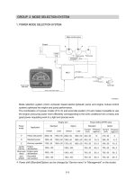
System Description
NGSC0004
KA24DE MODELS
NGSC0004S01
Power is supplied at all times
¼ through 40A fusible link (letter e, located in the fuse and fusible link box)
¼ to ignition switch terminal B.
With the ignition switch in the START position, power is supplied
¼ through ignition switch terminal ST
¼ to clutch interlock relay terminal 5.
With the ignition switch in the ON or START position, power is supplied
¼ through 10A fuse [No. 11, located in the fuse block (J/B)]
¼ to clutch interlock relay terminal 2.
With the clutch pedal depressed, ground is supplied
¼ to clutch interlock relay terminal 1
¼ through clutch interlock switch terminal 1
¼ through clutch interlock switch terminal 2
¼ through body grounds M14 and M68.
The clutch interlock relay is energized and power is supplied
¼ through clutch interlock relay terminal 3
¼ to starter motor windings terminal +.
The starter motor plunger closes and provides a closed circuit between the battery and the starter motor. The
starter motor is grounded to the cylinder block. With power and ground supplied, the starter motor operates.
STARTING SYSTEM
System Description
SC-6
VG33E M/T MODELS
=NGSC0004S02
Power is supplied at all times
¼ through 40A fusible link (letter e, located in the fuse and fusible link box)
¼ to ignition switch terminal B.
With the ignition switch in the START position, power is supplied
¼ through ignition switch terminal ST
¼ to clutch interlock relay terminal 5.
With the ignition switch in the ON or START position, power is supplied
¼ through 10A fuse [No. 11, located in the fuse block (J/B)]
¼ to clutch interlock relay terminal 2 and
¼ through 7.5A fuse [No. 5, located in the fuse block (J/B)]
¼ to theft warning relay terminal 2 (models with power door locks).
If the theft warning system is not triggered (models with power door locks) and clutch pedal is depressed,
ground is supplied
¼ to clutch interlock relay terminal 1
¼ through theft warning relay terminals 3, 4 (models with power door locks) and
¼ through clutch interlock switch terminal 1
¼ through clutch interlock switch terminal 2
¼ through body grounds M14 and M68.
The clutch interlock relay is energized and power is supplied
¼ through clutch interlock relay terminal 3
¼ to starter motor windings terminal +.
The starter motor plunger closes and provides a closed circuit between the battery and the starter motor. The
starter motor is grounded to the cylinder block. With power and ground supplied, the starter motor operates.
If the theft warning system is triggered (models with power door locks), ground is supplied to theft warning
relay terminal 1 through smart entrance control unit terminal 32, disengaging the clutch interlock relay and
preventing starter motor operation.
GI
MA
EM
LC
EC
FE
CL
MT
AT
TF
PD
AX
SU
BR
ST
RS
BT
HA
EL
IDX
STARTING SYSTEM
System Description (Cont’d)
SC-7
VG33E A/T MODELS
=NGSC0004S03
Power is supplied at all times
¼ through 40A fusible link (letter e, located in the fuse and fusible link box)
¼ to ignition switch terminal B.
With the ignition switch in the START position, power is supplied
¼ through ignition switch terminal ST
¼ to park/neutral position (PNP) relay terminal 5.
With the ignition switch in the ON or START position, power is supplied
¼ through 10A fuse [No. 12, located in the fuse block (J/B)]
¼ to PNP switch terminal 1 and
¼ through 7.5A fuse [No. 5, located in the fuse block (J/B)]
¼ to theft warning relay terminal 2 (models with power door locks).
With the selector lever in the P or N position, power is supplied
¼ through PNP switch terminal 2
¼ to PNP relay terminal 2.
If the theft warning system is not triggered (models with power door locks), ground is supplied
¼ to PNP relay terminal 1
¼ through body grounds E12 and E54 (models without power door locks) or
¼ through theft warning relay terminals 3, 4 (models with power door locks) and
¼ through body grounds M14 and M68.
The PNP relay is energized and power is supplied
¼ through PNP relay terminal 3
¼ to starter motor windings terminal +.
The starter motor plunger closes and provides a closed circuit between the battery and the starter motor. The
starter motor is grounded to the cylinder block. With power and ground supplied, the starter motor operates.
If the theft warning system is triggered (models with power door locks), ground is supplied to theft warning
relay terminal 1 through smart entrance control unit terminal 32, disengaging the PNP relay and preventing
starter motor operation.
STARTING SYSTEM
System Description (Cont’d)
SC-8