Industrial applications of programmable logic controllers and scada
Bạn đang xem bản rút gọn của tài liệu. Xem và tải ngay bản đầy đủ của tài liệu tại đây (4.29 MB, 82 trang )
Kunal Chakraborty
Palash De
Indranil Roy
INDUSTRIAL APPLICATIONS
OF PROGRAMMABLE LOGIC
CONTROLLERS AND SCADA
Anchor Academic Publishing
disseminate knowledge
Chakraborty, Kunal, De, Palash, Roy, Indranil: INDUSTRIAL APPLICATIONS OF
PROGRAMMABLE LOGIC CONTROLLERS AND SCADA, Hamburg, Anchor Academic
Publishing 2016
PDF-eBook-ISBN: 978-3-96067-524-2
Druck/Herstellung: Anchor Academic Publishing, Hamburg, 2016
Bibliografische Information der Deutschen Nationalbibliothek:
Die Deutsche Nationalbibliothek verzeichnet diese Publikation in der Deutschen
Nationalbibliografie; detaillierte bibliografische Daten sind im Internet über
abrufbar.
Bibliographical Information of the German National Library:
The German National Library lists this publication in the German National Bibliography.
Detailed bibliographic data can be found at:
All rights reserved. This publication may not be reproduced, stored in a retrieval system
or transmitted, in any form or by any means, electronic, mechanical, photocopying,
recording or otherwise, without the prior permission of the publishers.
Das Werk einschließlich aller seiner Teile ist urheberrechtlich geschützt. Jede Verwertung
außerhalb der Grenzen des Urheberrechtsgesetzes ist ohne Zustimmung des Verlages
unzulässig und strafbar. Dies gilt insbesondere für Vervielfältigungen, Übersetzungen,
Mikroverfilmungen und die Einspeicherung und Bearbeitung in elektronischen Systemen.
Die Wiedergabe von Gebrauchsnamen, Handelsnamen, Warenbezeichnungen usw. in
diesem Werk berechtigt auch ohne besondere Kennzeichnung nicht zu der Annahme,
dass solche Namen im Sinne der Warenzeichen- und Markenschutz-Gesetzgebung als frei
zu betrachten wären und daher von jedermann benutzt werden dürften.
Die Informationen in diesem Werk wurden mit Sorgfalt erarbeitet. Dennoch können
Fehler nicht vollständig ausgeschlossen werden und die Diplomica Verlag GmbH, die
Autoren oder Übersetzer übernehmen keine juristische Verantwortung oder irgendeine
Haftung für evtl. verbliebene fehlerhafte Angaben und deren Folgen.
Alle Rechte vorbehalten
© Anchor Academic Publishing, Imprint der Diplomica Verlag GmbH
Hermannstal 119k, 22119 Hamburg
, Hamburg 2016
Printed in Germany
ABSTRACT
Abstract: The book contains various applications of programmable logic
controllers and SCADA designing of a plant. Everyone knows, nowadays every
human handled plants are being replaced by the automatic control system, thus
called Automation. For the ease of access and for better precision the PLCs are
accepted worldwide. In this book Rockwell PLCs are described and so the
SCADA design also done by the RSView32 software, manufactured by
Rockwell. It is one of the biggest name in the PLC software industry, being easy
to use, control and modify. Some electrical drives, such as D.C drives, A.C
drives are also described in detail because the control part is done by the PLCs
but the main plant is based on these electrical drives.
1
ACKNOWLEDGEMENTS
We would like to give our sincere gratitude towards Mr. Bablu Bhattacharya, Chairman,
IMPS College of Engineering And Technology, Dr. S.K. Bhattacharya, Principal, IMPS
College Of Engineering And Technology and Mr. Sankha Subhra Ghosh, H.O.D., Dept. Of
Electrical Engineering, IMPSCET for their valuable suggestion and guidance. Without their
kind help this book would not have been formed. They gave us their valuable time and
information which has helped us to make this book more better.
2
PREFACE
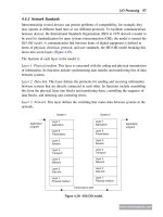
We have tried to write this book with our every possible positive effort. Various
informations and diagrams are given to help the readers to understand the chapter with more
ease. This is our initial try of writing, errors may be found in the book. Feedback from the
readers is highly appreciated.
3
TABLE OF CONTENTS
Abstract...........................................................................................................................1
Acknowledgments...........................................................................................................2
Preface.............................................................................................................................3
List of Figures.................................................................................................................7
Chapter 1. Introduction...................................................................................................11
Chapter 2. What is PLC....................................................................................12
2.1 Definition....................................................................................................12
2.2 Historical Background..................................................................................12
2.3 Application Fields of PLC............................................................................13
2.4 PLC Size.......................................................................................................13
2.5 Role of Electronics in Automation...............................................................16
2.6 The PLC System...........................................................................................17
2.7 Basic operations of PLC...............................................................................23
2.8 Memory Designs..........................................................................................26
2.9 Local Area Network (LAN).........................................................................30
2.11 Detailed Design of a PLC...........................................................................31
2.12 Examples of PLC Programming Software.................................................33
2.13 Programming..............................................................................................33
2.15 Ladder Logic..............................................................................................36
2.16 Timers and Counters..................................................................................51
Chapter 3. SCADA Design...........................................................................................54
3.1 Historical Data............................................................................................54
3.2 Communication Media...............................................................................54
3.3 Introduction to Designing...........................................................................55
3.4 Applications...............................................................................................56
3.4.1 Wastewater Treatment........................................................................56
3.4.2 Oil And Gas Production......................................................................56
3.5 Sample Diagram of SCADA Application..................................................57
Chapter 4. Electrical Drives...........................................................................................58
4.1 Introduction.................................................................................................58
4.2 Applications of Electric Drives...................................................................58
5
4.3 Electric Drives - A Definition.....................................................................58
4.4 Electric Machines........................................................................................59
4.5 Selection Criteria for Electric Machines.....................................................59
4.6 Components in Electric Drives....................................................................62
4.6.1 Motors....................................................................................................62
4.6.2 D.C Drives vs A.C Drives.....................................................................63
Chapter 5. Applications of PLC in Industry...................................................................66
5.1 Controlling the Filling and Capping Operation of a Bottling Plant............66
5.1.2 Introduction...........................................................................................66
5.1.3 Construction..........................................................................................67
5.1.4 Process Description...............................................................................68
5.1.5 Case Study.............................................................................................68
5.1.6 Control Philosophy.................................................................................70
5.1.7 SCADA Design......................................................................................70
5.2 Pump Control via Star Delta Starter..............................................................73
5.2.1 Introduction..............................................................................................73
5.2.2 Star Delta Starter......................................................................................74
5.2.2.1 Power Circuit....................................................................................74
5.2.2.2 Control Circuit..................................................................................74
5.2.3 Control Philosophy.................................................................................75
5.2.4 SCADA Design......................................................................................76
Chapter 6. Future Aspects............................................................................................78
6
LIST OF FIGURES
Fig1. Basic Components of a PLC.................................................................................17
Fig2. Some I/O devices of PLC.....................................................................................22
Fig3. I/O Module of Allen-Bradley PLC......................................................................22
Fig4. On Off Logic of a PLC……………………………………………….....………23
Fig5. Input Logic of PLC……………………………………………….....…………..24
Fig6. Output Logic of PLC.............................................................................................24
Fig7. Analog Output of a PLC.......................................................................................25
Fig8. Memory Map Organisation..................................................................................26
Fig9. PLC Scan Cycle...................................................................................................28
Fig10. Dedicated Network System of Different Manufacturers..………………….....30
Fig11. NO Contact…………………………………………,…………………...……33
Fig12. NC Contact………………………………………….…………………...……33
Fig13. Coils...................................................................................................................34
Fig14. Boxes..................................................................................................................34
Fig15. AND Operation Rung………………………………,…………………...……35
Fig16. OR Operation Rung...........................................................................................35
Fig17. NOT Operation Rung.........................................................................................35
Fig18. Ladder Logic......................................................................................................36
Fig19. Ladder Diagram with I/O detail included..........................................................37
Fig20. Coil representation ............................................................................................38
Fig21. Normally open and closed representation in a ladder diagram..........................38
Fig22. Follow-on state...................................................................................................39
Fig23. The NO and NC schematic representation for a limit switch............................39
Fig24. Push-button Application.....................................................................................40
Fig25. Circuit schematic with an AND configuration...................................................41
Fig26. Circuit schematic with an OR configuration......................................................42
Fig27. An OR branch for front and rear door bell operation.........................................44
7
Fig28. A compound branch configuration.....................................................................45
Fig29. An OR configuration for both I/O devices.........................................................45
Fig30. Associating I/O data...........................................................................................46
Fig31. Memory allocation for the Micrologix...............................................................47
Fig32. Data flow from PLC to controlled unit..............................................................48
Fig33. Data flow into the PLC from an input source....................................................49
Fig34. On-delay timer...................................................................................................51
Fig35. Off-delay timer...................................................................................................51
Fig36. Retentive timer...................................................................................................52
Fig37. Sample diagram of SCADA design...................................................................57
Fig38. VSD application.................................................................................................60
Fig39.Conventional electric drives................................................................................60
Fig40. Power electronics devices..................................................................................61
Fig41. Modern Drives...................................................................................................61
Fig42.Controllers...........................................................................................................61
Fig43. Controller Components......................................................................................62
Fig44. Newton’s Law for linear motion........................................................................65
Fig45. Rotational motion with constant J......................................................................65
Fig46. Block diagram of a PLC.....................................................................................68
Fig47. Coca-Cola bottling plant....................................................................................69
Fig48. Conveyer on.......................................................................................................70
Fig49. Empty bottles running........................................................................................71
Fig50. Bottles filling......................................................................................................71
Fig51. Filled bottles running.........................................................................................71
Fig52. Capping section..................................................................................................72
Fig53. Set of bottles running towards exit.....................................................................72
Fig54. Pump control system...........................................................................................76
Fig55. System is offline..................................................................................................76
8
Fig56. Motor starts.........................................................................................................76
Fig57. Water starts filling the tank.................................................................................77
Fig58. Motor stops when the level is high.....................................................................77
9
CHAPTER 1: INTRODUCTION
It is needless to say that water, a compound of Hydrogen and Oxygen is a
valuable natural gift which is very essential for survival of mankind including
animals. The water used for portable purposes should be free from undesirable
impurities. The water available from untreated sources like Well, Boreholes and
Spring is generally not hygienic and safe for drinking. Thus it is desirable and
necessary to purify the water and supply under hygienic conditions for human
drinking purpose.
In recent times the need of packaged beverages, such as drinking water is very
much high. In a beverage packaging industry the purity of the water is given the
main priority.
In a beverage industry, there are various steps to manufacture a product.
The materials are stored at various locations in the plant. These materials are to
be carefully routed between different points of the plant equipment as a part of
beverage manufacturing process. They are required to flow through different
pipes depending on the process. All the fixed pipes in a plant for material
routing have valves at the intersection points of pipes. To set a path through
these pipes for a material flow between any two points, respective valves in the
path should be operated in desired manner, depending on the kind of process
employed at that point of time.
In today’s era mankind are trying to implement some technology, which will
decrease its labour. Various technologies are implemented in this aspect, one of
them is industrial automation. The automation technology has changed the view
of controlling technology. It has made the manufacturing, packaging and
various stages of an industry very much precise and human friendly.
11
CHAPTER 2: WHAT IS PLC?
Definition:-A
digitally
operating
electronic
apparatus
which
uses
a
programming memory for the internal storage of instructions for implementing
specific functions such as logic, sequencing, timing, counting and arithmetic to
control through digital or analog modules, various types of machines or process.
Historical background: The controller had to be designed in modular form, so
that sub-assemblies could be removed easily for replacement or repair.
The control system needed the capability to pass data collection to a central
system. The system had to be reusable. The method used to program the
controller had to be simple, so that it could be easily understood by plant
personnel.
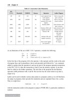
Some years of implementation of PLC devices is mentioned below:
1968: Programmable concept developed
1969: Hardware CPU controller, with logic instructions, 1 K of memory and
128 I/O points
1974: Use of several (multi) processors within a PLC - timers and counters;
arithmetic operations; 12 K of memory and 1024 I/O points
1976: Remote input/output systems introduced
1977: Microprocessors - based PLC introduced
1980 :Intelligent I/O modules developed (Enhanced communications facilities,
Enhanced software features)e.g. documentation
x Use of personal microcomputers as programming aids
1983: Low - cost small PLC’s introduced
1985 : Networking of all levels of PLC, computer and machine using SCADA
software.
Some PLC Renowned Manufacturers Are:
1. Allen Bradley
2. Gould Modicon
3. Texas Instruments
4. General Electric
12
5. Westinghouse
6. Cutter Hammer
7. Square D
8. Siemens
9. Klockner & Mouller
10. Festo
11. Telemechanique
12. Toshiba
13. Omron
14. Fanuc
15. Mitsubishi
Application Fields Of PLC:
Manufacturing / Machining
Food / Beverage
Metals
Power
Mining
Petrochemical / Chemical
PLC Size:
1. SMALL - it covers units with up to 128 I/O’s and
memories up to 2 Kbytes, these PLC’s are capable of providing simple to
advance levels or machine controls.
2. MEDIUM- have up to 2048 I/O’s and memories up to 32 Kbytes.
3. LARGE - the most sophisticated units of the PLC family. They have up to
8192 I/O’s and memories up to 750 Kbytes.
- can control individual production
processes or entire plant.
13
Control engineering has evolved over time. In the past humans were the main
methods for controlling a system. More recently electricity has been used for
control and early electrical control based on relays. These relays allow power to
be switched on and off without a mechanical switch.It is common to use relays
to make simple logical control decisions. The development of low cost
computer has brought the most recent revolution, the Programmable Logic
Controller (PLC) . The advent of the PLC began in the 1970s, and has become
the most common choice for manufacturing controls. PLCs have been gaining
popularity on the factory floor and will probably remain predominant for some
time to come. Most of this is because of the advantages they offer. Cost
effective for controlling complex systems.
• Flexible and can be reapplied to control other systems quickly and easily.
• Computational abilities allow more sophisticated control.
• Trouble shooting aids make programming easier and reduce downtime.
Reliable components make these likely to operate for years before failure. The
PLC was invented in response to the needs of the American automotive
manufacturing industry. Programmable logic controllers were initially adopted
by the automotive industry where software revision replaced the rewiring of
hard-wired control panels when production models changed. Before the PLC,
control, sequencing, and safety interlock logic for manufacturing automobiles
was accomplished using hundreds or thousands of relays, cam timers, and drum
sequencers and dedicated closed-loop controllers. The process for updating such
facilities for the yearly model change-over was very time consuming and
expensive, as electricians needed to individually rewire each and every relay.
Digital computers, being general-purpose programmable devices, were soon
applied to control of industrial processes. Early computers required specialist
programmers, and stringent operating environmental control for temperature,
cleanliness, and power quality. Using a general-purpose computer for process
control required protecting the computer from the plant floor conditions. An
industrial control computer would have several attributes: it would tolerate the
14
shop-floor environment, it would support discrete (bit-form) input and output in
an easily extensible manner, it would not require years of training to use, and it
would permit its operation to be monitored. The response time of any computer
system must be fast enough to be useful for control; the required speed varying
according to the nature of the process . In 1968 GM Hydramatic (the automatic
transmission division of General Motors) issued a request for proposal for an
electronic replacement for hard-wired relay systems. The winning proposal
came from Bedford Associates of Bedford, Massachusetts. The first PLC,
designated the 084 because it was Bedford Associates' eighty-fourth project,
was the result . Bedford Associates started a new company dedicated to
developing, manufacturing, selling, and servicing this new product: Modicum,
which stood for Modular Digital Controller. One of the people who worked on
that project was Dick Morley, who is considered to be the "father" of the PLC.
The Modicon brand was sold in 1977 to Gould Electronics, and later acquired
by German Company AEG and then by French Schneider Electric, the current
owner. One of the very first 084 models built is now on display at Modicon's
headquarters in North Andover, Massachusetts. It was presented to Modicon by
GM, when the unit was retired after nearly twenty years of uninterrupted
service. Modicon used the 84 moniker at the end of its product range until the
984 made its appearance. The automotive industry is still one of the largest
users of PLCs.
Early PLCs were designed to replace relay logic systems. These PLCs were
programmed in "ladder logic", which strongly resembles a schematic diagram of
relay logic. This program notation was chosen to reduce training demands for
the existing technicians. Other early PLCs used a form of instruction list
programming, based on a stack-based logic solver. Modern PLCs can be
programmed in a variety of ways.
Programmable logic controllers have been used extensively in industrial control
applications since their advent in the 70s. The programming of logic controllers
has been done majorly by the knowledge of the programmer and no formal
15
methods are used. Hence, the task of writing the code becomes a difficult one
with the efficiency of the code varying from programmer to programmer. The
ladder logic structure of coding PLCs makes it difficult to realize higher level
concepts such as function calls and looping. The discrete event based modeling
of systems provides a suitable sequential structure to the programming of PLCs.
ROLE OF ELECTRONICS IN AUTOMATION
A constant demand for better and more efficient manufacturing and
process machinery has led to the requirement for higher quality and reliability in
control techniques. With the availability of intelligent, compact solid state
electronic devices, it has been possible to provide control systems that can
reduce maintenance, down time and improve productivity to a great extend. By
installing efficient and user friendly industrial electronics systems for
manufacturing machinery or processors, one can obtain a precise, reliable and
prolific means for generating quality products.
Considering the varied demand and increasing competition, one has to
provide for flexible manufacturing process. One of the latest techniques in solid
state controls that offers flexible and efficient operation to the user is
“PROGRAMMABLE CONTROLLERS”.
The basic idea behind these
programmable controllers was to provide means to eliminate high cost
associated
with
inflexible,
conventional
relay
controlled
systems.
Programmable controllers offer a system with computer flexibility:
1. Suited to withstand the industrial environment
2. Has simplicity of operation
3. Maintenance by plant technicians.
4. Reduce machine down time and provide expandability for
future.
In recent times, the programmable logic controllers have gone through
various stages of development, and have become more and more reliable,
time saving device.
16
Some major components of a PLC is discussed below:
The PLC system
A programmable logic controller consists of the following components:
x Central Processing Unit (CPU)
x Memory
x Input modules
x Output modules
x Power supply.
A PLC hardware block diagram is shown in Figure . The programming terminal
in the diagram is not a part of the PLC, but it is essential to have a terminal for
programming or monitoring a PLC. In the diagram, the arrows between blocks
indicate the information and power flowing directions.
Programming
Terminal
Input
Module
Output
CPU
Memory
Power Supply
Fig 1.Basic Components Of a PLC
17
Modul
e
CPU
Like other computerized devices, there is a Central Processing Unit (CPU) in a
PLC. The CPU, which is the “brain” of a PLC, does the following operations:
x Updating inputs and outputs. This function allows a PLC to read the
status of its input terminals and energize or deenergize its output
terminals.
x Performing logic and arithmetic operations. A CPU conducts all the
mathematic and logic operations involved in a PLC.
x Communicating with memory. The PLC’s programs and data are stored
in memory. When a PLC is operating, its CPU may read or change the
contents of memory locations.
x Scanning application programs. An application program, which is called
a ladder logic program, is a set of instructions written by a PLC
programmer. The scanning function allows the PLC to execute the
application program as specified by the programmer.
x Communicating with a programming terminal. The CPU transfers
program and data between itself and the programming terminal.
A PLC’s CPU is controlled by operating system software. The operating
system software is a group of supervisory programs that are loaded and stored
permanently in the PLC’s memory by the PLC manufacturer.
Memory
Memory is the component that stores information, programs, and data in a PLC.
The process of putting new information into a memory location is called
writing. The process of retrieving information from a memory location is called
reading.
18
The common types of memory used in PLCs are Read Only Memory (ROM)
and Random Access Memory (RAM). A ROM location can be read, but not
written. ROM is used to store programs and data that should not be altered. For
example, the PLC’s operating programs are stored in ROM.
A RAM location can be read or written. This means the information stored in a
RAM location can be retrieved and/or altered. Ladder logic programs are stored
in RAM. When a new ladder logic program is loaded into a PLC’s memory, the
old program that was stored in the same locations is over-written and essentially
erased.
The memory capacities of PLCs vary. Memory capacities are often expressed in
terms of kilo-bytes (K). One byte is a group of 8 bits. One bit is a memory
location that may store one binary number that has the value of either 1 or 0.
(Binary numbers are addressed in Module 2). 1K memory means that there are
1024 bytes of RAM. 16K memory means there are 16 x 1024 =16384 bytes of
RAM.
Input modules and output modules
A PLC is a control device. It takes information from inputs and makes decisions
to energize or de-energize outputs. The decisions are made based on the statuses
of inputs and outputs and the ladder logic program that is being executed.
The input devices used with a PLC include pushbuttons, limit switches, relay
contacts, photo sensors, proximity switches, temperature sensors, and the like.
These input devices can be AC (alternating current) or DC (direct current). The
input voltages can be high or low. The input signals can be digital or analog.
Differing inputs require different input modules. An input module provides an
interface between input devices and a PLC’s CPU, which uses only a low DC
voltage. The input module’s function is to convert the input signals to DC
voltages that are acceptable to the CPU. Standard discrete input modules
19
include 24 V AC, 48 V AC, 120 V AC, 220 V AC, 24 V DC, 48 V DC, 120 V
DC, 220 V DC, and transistor-transistor logic (TTL) level.
The devices controlled by a PLC include relays, alarms, solenoids, fans, lights,
and motor starters. These devices may require different levels of AC or DC
voltages. Since the signals processed in a PLC are low DC voltages, it is the
function of the output module to convert PLC control signals to the voltages
required by the controlled circuits or devices. Standard discrete output modules
include 24 V AC, 48 V AC, 120 V AC, 220 V AC, 24 V DC, 48 V DC, 120 V
DC, 220 V DC, and TTL level.
Different Types OF I/O Modules:
1. Pilot Duty Outputs
Outputs of this type typically are used to drive high-current electromagnetic
loads such as solenoids, relays, valves, and motor starters.
These loads are highly inductive and exhibit a large inrush current.
Pilot duty outputs should be capable of withstanding an inrush current of 10
times the rated load for a short period of time without failure.
2. General - Purpose Outputs
These are usually low- voltage and low-current and are used to drive indicating
lights and other non-inductive loads. Noise suppression may or may not be
included on this types of modules.
3. Discrete Inputs
Circuits of this type are used to sense the status of limit switches, push buttons,
and other discrete sensors. Noise suppression is of great importance in
preventing false indication of inputs turning on or off because of noise.
20
4. Analog I/O
Circuits of this type sense or drive analog signals.
Analog inputs come from devices, such as thermocouples, strain gages, or
pressure sensors, that provide a signal voltage or current that is derived from the
process variable.
Standard Analog Input signals: 4-20mA; 0-10V
Analog outputs can be used to drive devices such as voltmeters, X-Y recorders,
servomotor drives, and valves through the use of transducers.
Standard Analog Output signals: 4-20mA; 0-5V; 0-10V
5. Special - Purpose I/O
Circuits of this type are used to interface PLCs to very specific types of circuits
such as servomotors, stepping motors PID (proportional plus integral plus
derivative) loops, high-speed pulse counting, resolver and decoder inputs,
multiplexed displays, and keyboards.
This module allows for limited access to timer and counter presets and other
PLC variables without requiring a program loader.
Power Supply
PLCs are powered by standard commercial AC power lines. However, many
PLC components, such as the CPU and memory, utilize 5 volts or another level
of DC power. The PLC power supply converts AC power into DC power to
support those components of the PLC.
21
Programming Terminal
A PLC requires a programming terminal and programming software for
operation. The programming terminal can be a dedicated terminal or a generic
computer purchased anywhere. The programming terminal is used for
programming the PLC and monitoring the PLC’s operation. It may also
download a ladder logic program (the sending of a program from the
programming terminal to the PLC) or upload a ladder logic program (the
sending of a program from the PLC to the programming terminal).
The
terminal uses programming software for programming and “talking” to a PLC.
Some Major Components Of A PLC:
Fig2. Some I/O devices Of PLC
Fig3. I/O Module Of Allen-Bradley PLC
22
Basic Operations of PLC:
Discrete Inputs:A discrete input also referred as digital input is an input that is either ON or
OFF are connected to the PLC digital input. In the ON condition it is referred to
as logic 1 or a logic high and in the OFF condition maybe referred to as logic o
or logic low.
Normally Open Pushbutton
Normally Closed Pushbutton
Normally Open switch
Normally Closed switch
Normally Open contact
Normally closed contact
Fig4. On Off Logic Of a PLC
23