link full solutions manual digital systems principles applications 11th edition tocci
Bạn đang xem bản rút gọn của tài liệu. Xem và tải ngay bản đầy đủ của tài liệu tại đây (1000.42 KB, 7 trang )
Solution Manual for Digital Systems: Principles and
Applications 11th edition by Neal Widmer and Greg Moss
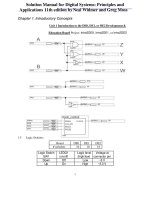
Chapter 1. Introductory Concepts
Unit 1 Introduction to the DE0, DE1, or DE2 Development &
Education Board Project: Intro2DE0, Intro2DE1, or Intro2DE2
1.3
Logic Switches
Board
# switches
Logic Switch
SW1
Down
Up
DE0
10
LEDG1
(on/off)
Off
On
DE1
10
DE2
18
Logic level
Voltage at
(high/low) connector pin
Low
~0 V
High
~3.3 V
1
1.4
LEDs
LED label
LEDR
LEDG
1.5
Pushbuttons
Color
Red
Green
DE1
10
8
DE2
18
9
Normally High
Board
Pushbutton
Pushbutton
#1
Normal
Pressed
1.6
DE0
0
10
DE0
3
DE1
4
DE2
4
LEDG2 LEDG3
(on/off) (on/off)
On
Off
Off
On
Clock
CLK_ON (SW9)
SEL[1..0] (SW8, SW7)
freqG0
1
00
0.5 Hz
1
01
5 Hz
1
10
25 Hz
1
11
50 Hz
0
XX
0 Hz
1.7 Simple logic circuits
A
(SW3)
0
0
1
1
W = B
B
(SW2)
0
1
0
1
W
(LEDG4)
0
1
0
1
X
(LEDG5)
1
0
1
0
_
X = B
Y
(LEDG6)
0
1
1
1
Y = A + B
2
Z
(LEDG7)
0
0
0
1
Z = A B
Unit 2 Testing Combinational Logic Circuits Using DE0, DE1, or DE2 Boards
Project: Lab2DE0, Lab2DE1, or Lab2DE2
3
4
2.1 Simple circuits
_
Y = A + A B = A + B
_
_
T = A B + A B + A B = A + B
X = A + A B = A
_
Z = A (A + B) = A B
A
0
0
1
1
2.2
B
0
1
0
1
More circuit functions
___
V = A B
_
_
J = A B + A B = A
T
0
1
1
1
Z
0
0
0
1
Y
0
1
1
1
X
0
0
1
1
J
0
1
1
0
K
1
0
0
1
W
1
0
0
0
V
1
1
1
0
_____
W = A + B
_ _
∀ B
K = A B + A B = A
5
_____
∀ B
Unit 3 Schematic Capture & Analysis of Combinational Logic Circuits
3.1
Example 3-1 (see Lab Manual Example 3-1 & Quartus Tutorial 1 – Schematic)
3.2
Equivalent circuits
(a)
V = W?
true
V = A (B + C)
W = A C + A B
(b)
X = Y?
_
X = A B
_
Y = A B
true
_
+ A B + A C
_
_
+ A B + B C
A
0
0
0
0
1
1
1
1
B
0
0
1
1
0
0
1
1
C
0
1
0
1
0
1
0
1
V
0
0
0
0
0
1
1
1
W
0
0
0
0
0
1
1
1
X
1
1
0
0
0
1
1
1
Y
1
1
0
0
0
1
1
1
3.3DeMorgan’s theorem
(a)
p1 = p2 = p3?
_ _
p1 = a b
(b)
true
_ _
p2 = a b
_____
p3 = a + b
q1 = q2 = q3?
true
_
_
q1 = a + b
_
_
q2 = a + b
a
0
0
1
1
b
0
1
0
1
p
1
0
0
0
6
q
1
1
1
0
___
q3 = a b
3.4
2-bit adder
7