Mô phỏng tai nạn mất chất làm lạnh của lò phản ứng nước áp lực PWR bằng phần mềm PC TRAN
Bạn đang xem bản rút gọn của tài liệu. Xem và tải ngay bản đầy đủ của tài liệu tại đây (2.54 MB, 83 trang )
VIETNAM NATIONAL UNIVERSITY – HO CHI MINH CITY
UNIVERSITY OF SCIENCE
FACULTY OF PHYSICS AND ENGINEERING PHYSICS
DEPARTMENT OF NUCLEAR PHYSICS
-------------------
UNDERGRADUATE THESIS
STUDYING A LOSS - OF - COOLANT ACCIDENT (LOCA)
OF PRESSURIZED WATER REACTOR (PWR)
BY PCTRAN SOFTWARE
STUDENT: NGUYEN VAN THANG
SUPERVISOR: Dr. VO HONG HAI
REVIEWER: Dr. HUYNH TRUC PHUONG
HO CHI MINH CITY – 2012
ACKNOWLEDGEMENTS
------------------Foremost, I would like to express my sincere gratitude to my supervisor
Dr. Vo Hong Hai. He has been a knowledgeable, competent and helpful advisor, as
well as a very kind-hearted and humble person. I have greatly appreciated working
and learning under his guidance.
I also thank Dr. Huynh Truc Phuong who is my reviewer spent a lot of time
to read and give me the honest feedbacks.
Besides that, I would like to thank MSc. Nguyen Quang Duy who is the
predecessors and the brother. He is the person who provided me the simulation
software, books and the precious experience.
I am grateful to Prof. Chau Van Tao, the Dean of the Nuclear Physics
department who facilitated my study complete on the schedule. I also thank teachers
of Department of Nuclear Physics and Faculty of Physics and Engineering Physics
provided me a lot of knowledge during four years at the Science University.
I also thank my friends, for giving advices and help me much during the
execution time of my thesis.
Last but not the least; I would like to thank my parents, for given the birth
to me at the fist place and supporting me spiritually throughout my life.
Ho Chi Minh City, June 17th 2012
NGUYEN VAN THANG
[i]
CONTENTS
Page
Contents ................................................................................................................... i
List of Abbreviations and Symbols ........................................................................ iii
List of Tables ......................................................................................................... iv
List of Figures ......................................................................................................... v
Preface .................................................................................................................... 1
Chapter 1: BACKGROUND ................................................................................... 3
1.1. Introduction to nuclear power ........................................................................... 3
1.1.1. Nuclear power on the world ........................................................................ 3
1.1.2. Nuclear power necessity and the plan of nuclear power in Vietnam ............ 4
1.2. Principle of nuclear reactor ............................................................................... 5
1.2.1. Neutron properties in nuclear reactor .......................................................... 5
1.2.1.1. Neutron interaction cross section ........................................................... 5
1.2.1.2. Neutron flux .......................................................................................... 6
1.2.1.3. Neutron current density ......................................................................... 7
1.2.1.4. Neutron slowing down........................................................................... 7
1.2.1.5. Neutron diffusion .................................................................................. 8
1.2.2. Nuclear fission reaction............................................................................... 9
1.2.3. Radiation decay......................................................................................... 11
1.2.4. Fuel material – coolant interaction ............................................................ 12
1.2.5. Core-Concrete interaction ......................................................................... 14
1.3. Pressurized Water Reactor (PWR) .................................................................. 14
1.3.1. Development history ................................................................................. 14
3.1.2. Operation principle ................................................................................... 15
3.1.3. PWR structure ........................................................................................... 16
3.1.3.1. Reactor core ........................................................................................ 16
3.1.3.2. Reactor coolant .................................................................................... 18
3.1.3.3. Moderator ............................................................................................ 18
3.1.3.4. Control rods system ............................................................................. 18
3.1.3.5. Reactor vessel ...................................................................................... 18
[ii]
3.1.3.6. Pressurizer ........................................................................................... 19
3.1.3.7. Steam generator ................................................................................... 20
3.1.3.8. Containment system ............................................................................ 22
Chapter 2: INTRODUCTION TO PCTRAN PWR SOFTWARE
VERSION 4.0.8 ................................................................................... 23
2.1. PCTRAN overview ......................................................................................... 23
2.2. Introduction to PCTRAN PWR version 4.0.8 ................................................. 25
2.3. PCTRAN PWR interface (main micmic) ........................................................ 26
2.4. Simulation an accident .................................................................................... 32
2.4.1. Malfunction setup ..................................................................................... 32
2.4.2. Initial conditions set up ............................................................................. 34
2.4.3. Run simulation .......................................................................................... 34
2.5. PWR plant system control .............................................................................. 36
Chapter 3: SIMULATING A LOSS-OF-COOLANT ACCIDENT BY PCTRAN
PWR SOFTWARE .............................................................................. 37
3.1. Accident description ....................................................................................... 37
3.1.1. Coolant ..................................................................................................... 37
3.1.2. LOCA ....................................................................................................... 37
3.1.3. PWR LOCA .............................................................................................. 38
3.2. Set up simulation ............................................................................................ 39
3.3. Run simulation ............................................................................................... 40
3.4. Simulation analysis ......................................................................................... 42
3.4.1. SBLOCA properties .................................................................................. 42
3.4.2. LOCA consequences ................................................................................. 48
3.4.3. Radiological consequences ........................................................................ 49
3.4.3.1. Inside reactor radiation dose ................................................................ 49
3.4.3.2. Outside reactor radiation dose.............................................................. 50
CONCLUSIONS AND PROPOSALS ................................................................... 52
RFERENCES ........................................................................................................ 54
APPENDICES....................................................................................................... 57
[i]
LIST OF ABBREVIATIONS AND SYMBOLS
PCTRAN
Personal Computer Transient Analyzer
PWR
Pressurized Water Reactor
BWR
Boiling Water Reactor
LOCA
Loss-of-Coolant Accident
ECCS
Emergency Core Cooling System
HPIS
High Pressure Injection System
LPIS
Low Pressure Injection System
PCS
Primary Coolant System
EAB
Exclusion Area Boundary
LBZ
Low Population Zone
IAEA
International Atomic Energy Agency
INES
International Nuclear and Radiological Event Scale
USNRC
United State Nuclear Regulatory Commission
σ
Microscopic cross section (cm2 or barn)
Σ
Macroscopic cross section (cm-1)
λ
Mean free path of neutron (cm)
Ф
Neutron flux (neutron.cm-2.s-1)
Eth
Threshold energy of fission (MeV)
[ii]
LIST OF TABLES
Page
Table 1.1: Threshold energy and binding energy of some fissionable nuclei .......... 9
Table 1.2: Energy distribution of 235U fission reaction ......................................... 10
Table 1.3: Components of concrete...................................................................... 14
Table 3.1: Comparison of LOCA frequency from studies .................................... 38
Table 3.2: Summary table of the set up accident .................................................. 40
Table 3.3: Main events during the transient ......................................................... 42
Table 3.4: Exposure dose rate inside and out side reactor during simulation ........ 51
[iii]
LIST OF FIGURES
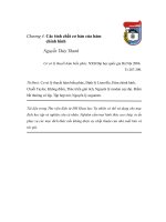
Figure 1.1: Nuclear electricity production from 1971 to 2009 ................................ 1
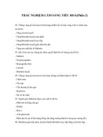
Figure 1.2: Statistic of operating reactors number on the world and electricity
production from 2000 to 2008............................................................. 2
Figure 1.3: Schematic diagram of neutron interaction in the center of mass
coordinate system ............................................................................... 7
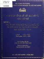
Figure 1.4: Schematic diagram of the fuel rod ..................................................... 12
Figure 1.5: Schematic diagram of pressurized water reactor system..................... 16
Figure 1.6: Schematic diagram of fuel pellet........................................................ 16
Figure 1.7: Schematic diagram of the PWR fuel rod ............................................ 17
Figure 1.8: A grid of 17×17 fuel assembly ........................................................... 17
Figure 1.9: Schematic diagram of PWR fuel assembly ........................................ 17
Figure 1.10: Schematic diagram of PWR vessel .................................................. 19
Figure 1.11: Schematic diagram of presurizer operation ...................................... 20
Figure 1.12: Schematic diagram of the U-Tube generator .................................... 21
Figure 1.13: Schematic diagram of containment system ...................................... 22
Figure 2.1: PCTRAN interface for PWR 2 loops ................................................. 26
Figure 2.2: Menu bar and the toolbar of PCTRAN............................................... 26
Figure 2.3: Status bar of PCTRAN ...................................................................... 27
Figure 2.4: A loop of PCTRAN ........................................................................... 27
Figure 2.5: Control operation status of reactor ..................................................... 28
Figure 2.6: Status of the reactor protection system (RPS) and the emergency
core cooling system (ECCS) ............................................................. 29
Figure 2.7: Operation parameter of the core......................................................... 29
Figure 2.8: Status parameter of reactor building .................................................. 30
Figure 2.9: Emergency core cooling system ........................................................ 31
Figure 2.10: Secondary coolant system of PWR .................................................. 31
Figure 2.11: Pumps and the valves operation status ............................................. 32
[iv]
Figure 2.12: Malfunction setup ............................................................................ 33
Figure 2.13: Initial condition setup ...................................................................... 33
Figure 2.14: Graphs of PCTRAN ........................................................................ 34
Figure 2.15: Dose micmic.................................................................................... 35
Figure 3.1: Setting up malfunction....................................................................... 39
Figure 3.2: Change malfunction status of the pump ............................................. 39
Figure 3.3: Choose an initial condition in Initial Conditions window ................... 40
Figure 3.4: PCTRAN display in 110s .................................................................. 41
Figure 3.5: Graph of pressure for SBLOCA......................................................... 43
Figure 3.6: Graph of neutron flux ........................................................................ 43
Figure 3.7: Graph of thermal power ..................................................................... 43
Figure 3.8: Graph of the leakage coolant flow ..................................................... 44
Figure 3.9: Graph of temperature of fuel and cladding ......................................... 44
Figure 3.10: Graph of cladding failure ................................................................. 45
Figure 3.11: Activity of 131I, 135Xe, 138Xe and 87Kr in coolant .............................. 45
Figure 3.12: Background of PCTRAN in 2620s .................................................. 46
Figure 3.13: Dependence of temperature of fuel to HPIS activation time ............. 47
Figure 3.14: Dependence of temperature of coolant to HPIS activation time ....... 47
Figure 3.15: Exposure dose inside reactor............................................................ 49
Figure 3.16: Dose rate EAB thyroid and whole body ........................................... 50
[1]
PREFACE
2011 is the year when many countries in the world experienced the largest
crisis of nuclear energy in the history. That caused Fukushima Daiichi nuclear
power plant disaster on March in Fukushima prefecture, Japan . This accident one
more time was an alarm for the safety of nuclear power plants, which are the main
electric supply of many development countries. After the event, the Government of
several nations declared their nuclear programs to use safer energy source.
In Vietnam, in recent years, the lack of electricity has been more and more
serious. Some of the traditional energy sources are running out. Hydropower is not
enough for requirement. Besides that, the construction many hydropower plants
always accompanied many bad effects for environment. Vietnam cannot use
popular infinity energy (e.g. wind energy, solar energy) because of the high price.
Therefore, the Government of Vietnam decided to build the nuclear power plants
though the society had many contrast opinions. On June 17th 2010, Prime Minister
makes a decision about the development orientation of the nuclear power in
Vietnam henceforth to 2030. Follow that, until 2030, Vietnam will have 13 nuclear
power units. The important problem is the human resource. Currently, the resource
for nuclear power is poor, thus, the Government is planning to widen and upgrade
training facilities. The target is training engineers who will work for the nuclear
power plants.
The use of software for simulation reactor is popular in the world. Many
countries use reactor simulation software for training at the universities. Nowadays,
there are many computer programs simulating for reactor operation (e.g. CASSIM,
RELAP and CATHARE). PCTRAN is also the simulation software for reactor. The
feature of this software is focusing to simulation of reactor accidents.
In Vietnam, PCTRAN has been only used for research for the recent years.
PCTRAN was also the subject of a few science articles of the Vietnam Atomic
Energy Institute. In 2010, the master thesis “Tìm hiểu cấu trúc và mô phỏng sự cố
lò phản ứng nước áp lực hai vòng bằng phần mềm PCTRAN” of MSc. Nguyen
[2]
Quang Duy was performed at Can Tho University. In the thesis, he simulated two
accidents of pressurized water reactor. Those were “Loss of Main Feed Pumps” and
“Turbine Trip”. From March 7th, 2011 to March 9th, 2011, the International Atomic
Energy Agency (IAEA) held the workshop to train for the staff of Vietnam Agency
for Radiation and Nuclear Safety using PCTRAN to simulation the various accident
situations.
In this thesis, we also used this PCTRAN version provided license by IAEA. A
loss-of-coolant accident was simulated.
The thesis includes three chapters:
Chapter 1: Background
This chapter provides the basic knowledge on nuclear power and nuclear reactor
physics. The principle operation and structure of a typical pressurized water
reactor is described clearly to build the background for the simulation in chapter 3.
Chapter 2: Introduction to PCTRAN PWR software version 4.0.8
This chapter introduces briefly to the PCTRAN software and guides to use
PCTRAN software to simulate the various accidents.
Chapter 3: Studying a loss-of-coolant accident (LOCA) by PCTRAN PWR software
In this chapter, we simulate the loss-of-coolant accident. During the transient the
ECCS is disabled. Base on simulation results, we study the response of the reactor
to the severe accident.
[3]
Chapter 1
BACKGROUND
1.1. Introduction to nuclear power
1.1.1. Nuclear power in the world [9], [10], [11], [17], [18], [25]
Nuclear power is the use of sustained nuclear fission to generate heat and
electricity. Nuclear power plants provide 6% of the world’s energy and 13-14%
world electricity [9]. In 2007, the International Atomic Energy Agency (IAEA)
reported there were 439 nuclear power reactors in operation on the world, operating
at 34 countries [9]. On December 2009, there were 436 nuclear power reactors
operating on the world with total power is 370499 MWe. There were 5 nuclear
power reactors in long term shutdown and 62 nuclear power reactors under
construction [10]. Since the commercial nuclear power plant operated in the middle
of 1950s, 2008 was the first year that no new nuclear power plant was connected to
the grid, although two were connected in 2009 [17].
Figure 1.1: Nuclear electricity production from 1971 to 2009 [25]
The accident of Three Mile Island nuclear power plant in the south of
Harrisburg, Pennsylvania, United State on March 28th 1979 led to partial melting
down and released a small amount of radioactive gases and radioactive Iodine into
[4]
environment [18]. After that, there has been no new nuclear reactor operating in The
United State. The accident of Chernobyl nuclear power plant in Ukraine on April
26th, 1986 released amount of radioactive materials which are 4 times larger than
their from Hiroshima atomic bomb disaster [11]. The accident made the concern
about safety of nuclear power plants, and delayed nuclear program in many years
later. Most recently, The Fukushima Daiichi nuclear power plants accident in
Fukushima prefecture, Japan on March 11th, 2011 caused a nuclear crisis. Many
nations considered to give up nuclear power to use a safer power.
Figure 1.2: Statistic of operating reactors number in the world and electricity
production from 2000 to 2008 [17]
Figure 1.2 shows the chart of nuclear power usage on the world from 2000 to
2008. The column chart is the operating reactors in the world and the line chart is
the percentage of global electricity production. The number of nuclear reactors has
not changed more and there has been a decline of nuclear power production from
16.7% in 2000 to 13.5% in 2008 [20].
1.1.2. The necessity and the plan of nuclear power in Vietnam [6], [16]
With the development of industries, social rapidly in Vietnam, nuclear power
should be considerable and necessary for the future electricity shortage, while hydro
and thermal plants are not enough supply. The fossil energy is also running out
while nuclear resources have just mined. Follow the statistic [16], total Uranium
resources that were mined in 2007 were 5.5 million tons increased 17% compare
[5]
with the level of 2005. At current 2006 rates of consumption, identified resources
are sufficient for about 100 years of supply. Total undiscovered resources
(prognosticated resources and speculative resources) in 2007 amounted to more
than 10.5 million tons increasing by 485000 tons from the total reported in 2005. At
the end of 2006, there were 435 commercial nuclear reactors were operating with a
net generating capacity of about 370GWe, requiring about 66500 tons of Uranium.
By 2030, a world nuclear capacity will grow between 509GWe and 663GWe,
Uranium requirement is between 93775 and 121955 tons [16]. Therefore, nuclear
energy will remain the main energy of future.
Vietnam plan to build the fist two nuclear power plants Ninh Thuan I and Ninh
Thuan II. Ninh Thuan I nuclear power plant (NPP) will be schedule to operate in
2021. This reactor is constructed as a pressurized water reactor following Russian
technique VVER. Ninh Thuan II will operate in 2020, construction follows
Japanese technique. Vietnam also plan for more 11 NNPs for later. It expected that
electric power from NNPs will reach to 15000MWe and occupy 10% total electric
power [6].
1.2. Principle of nuclear reactor
A nuclear reactor may be defined is the instrument that energy is released by
chain reaction between neutron and fissile nuclides. Heat which is generated by
fission and radiation is used to covert to electricity. The system operation is
researched by principle of classical gas dynamic. However, the interaction among
component particles is explained by the concepts of nuclear physics.
1.2.1. Neutron properties in nuclear reactor
1.2.1.1. Neutron interaction cross section [3]
The interaction of neutrons in nuclear reactor is separated into 4 kinds: elastic
scattering, inelastic scattering, capture radiation and fission. The probability
interaction of a neutron and a nucleus is measured by microscopic cross section σ. If
we sign σ e is the elastic scattering cross section, σ i is the inelastic scattering cross
[6]
section, σ c is the capture radiation cross section and σ f is the fission cross section, σ
may be written by formula (1.1).
σ = σ e + σi + σ c + σ f
(1.1)
Formula (1.1) can be rewrite
σ = σs + σ a
(1.2)
In formula (1.2) σ s is the scattering cross section and σ a is the absorption cross
section and
σs = σ e + σi
(1.3)
σa = σc + σf
The interaction cross section between a nucleus
235
(1.4)
U and a neutron with 2200
m/s velocity, 0.0253 eV is σ = 697 10-24 cm2 or 697 barn. The value is divided into
σs =10 barn, σc =107 barn and σf = 580 barn [3].
Σ = N σ, with N is the number of nuclei per a unit volume, is called
macroscopic cross section. The usual unit of Σ is cm-1. The attenuation of neutron in
the distance x is presented by [3]
j = j0e-Σx
(1.5)
Where j0 is the number of incident neutrons. The mean free path λ is the
inversion of Σ [3]
λ=
1
(1.6)
1.2.1.2. Neutron flux [3]
Neutron flux is one of concepts used popularly in nuclear reactor physics.
Considering a neutron in a reactor have homogeneous material with macroscopic Σ,
n neutrons per cm3 and neutron velocity is v. The reaction rate or the number of
reactions per a cm3 is R = nvΣ . The quantity which is calculated follow formula
(1.7) [3] is called neutron flux.
R
(1.7)
Σ
Thermal neutron distribution depends on neutrons velocity by Maxwell
Φ = nv =
equation (1.8) and is called Maxwell distribution [3].
[7]
n(v) = n 0 Av 2e
-
mv2
2kT
(1.8)
Where
3
m 2
A=4π
(1.9)
2πkT
The average velocity and the maximum velocity of neutron is calculated by
formula (1.10) and (1.11)
v
8kT
πm
(1.10)
vp
2kT
m
(1.11)
In formula (1.8), (1.9), (1.10) and (1.11), m is the neutron mass, T is
temperature in Kelvin and k is the Boltzmann constant.
1.2.1.3. Neutron current density [3]
Neutron current density in a volume unit is given by equation (1.12). Equation
(1.12) is the equation of Fick law.
j = D
With
(1.12)
λ
is the gradient operator; D = t
x y z
3
coefficient; and λ t =
is the diffusion
d
with d is the extrapolated length.
0.7
1.2.1.4. Neutron slowing down [3]
In the reactor, neutrons scatter on coolant. This progress make neutron lose
energy.
v'
v
θc
V
Figure 1.3: Schematic diagram of neutron interaction in the center of mass
coordinate system
[8]
It is assumed that E and E’ is the neutron energy before and after interaction;
θ c is the deviation angle of neutron in the center of mass coordinate system.
E' v' 1 + 2Acosθc + A 2
1+α
1 α
=
=
=
+
2
E
v
(1 + A)
2
2cosθc
(1.13)
2
A-1
Where α =
with A is the nucleus mass.
A+1
The scattering angle of neutron in laboratory system is calculated by (1.14).
cosθ =
1+Acosθc
1+2Acosθc +A 2
(1.14)
The average energy loss in each interaction ξ depends on nucleus mass number
A. For 1H, ξ = 1; 2H, ξ = 0.7261. It proves that 1H is the best slowing down
material.
ξ=1+
αlnα
1-α
(1.15)
1.2.1.5. Neutron diffusion [3], [22]
In the reactor, neutron distribution is very complex. To find neutron flux
distribution in reactor, we consider three progresses: diffusion or leak, absorption,
production.
The leak rate L per a unit volume is written
L = -D
(1.16)
2
2
2
Where is the Laplace 2 2 2
x
y z
The absorption rate of neutron per a unit volume is given by
A a
(1.17)
In the critical reactor, the number of neutrons per a unit volume is unchanged.
Thus, there is a balance among the neutron production rate S, neutron absorption
rate A and neutron leak rate L.
D a S 0
(1.18)
[9]
Equation (1.18) is the neutron diffusion equation which is the basic equation in
nuclear reactor physics. The solution of the equation is the neutron flux distribution
in the reactor.
1.2.2. Nuclear fission reaction [1], [2], [3], [22]
Nuclear fission is a type of nuclear reactor which is main energy source of
nuclear reactor. A fission reaction is the division a fissile nucleus such as
235
U to
two or many nucleus. Fist 235U absorbs a neutron and becomes an excited nucleus.
235
92
The (
236
U 01 n
236
92
U
*
(1.19)
*
U) nucleus can emit a gamma decay and becomes
with haft life 2.4 107 years. The probability which a
235
236
U stable nucleus
U absorbs a neutron and
emits a gamma decay is 16%. 84% left is fission.
235
92
*
Z
236-A-n
1
U + 01 n ( 236
92 U) A X +
92-ZY + n 0 n + Q
A typical fission reaction of
235
(1.20)
U [3]
*
139
94
1
( 236
92 U) 56 Ba 36 Kr 3 0 n 190MeV
(1.21)
Fission depends on the excitation energy E* of composite nucleus. Fission only
occurs when E* is higher than threshold energy Eth. Eth is calculated by formula
(1.22) [1] where Z2/A is the fission coefficient.
Z2
E th = 0.18A 2/3 5.2 - 0.117 MeV
(1.22)
A
If binding energy of the composite nucleus is higher than Eth, the nucleus has
fission with any neutron kinetic energy. Whereas, the binding energy of the
composite nucleus is lower than Eth, fission only happens when kinetic energy of
neutron is higher than Eth.
Table 1.1: Threshold energy and binding energy of some fissionable nuclei [2]
Nucleus
232
Th
U
235
U
238
U
239
Pu
233
Threshold energy Eth
(MeV)
5.9
5.5
5.75
5.85
5.5
Composite nucleus
(233Th)*
(234U)*
(236U)*
(239Pu)*
(240Pu)*
Binding energy BE of
composite nucleus
5.07
6.77
6.4
4.76
6.38
[10]
Recording to table 1.1, we can see
233
U,
235
U and
239
Pu have BE > Eth.
Therefore, these nuclei get are fissionable with any kinetic energy including thermal
neutron. They are called fissionable nuclei.
232
Th and 238U are fissionable with only
neutrons which have kinetic energy higher than Eth. Normally,
are used as fuel in thermal reactors and
reactors.
233
232
Th,
238
U and
235
232
U exist in nature.
Th and
238
238
233
U,
235
U and
239
Pu
U are used as fuel in fast
U occupies 0.7% natural Uranium.
U and 239Pu are produced in reactors by reactions (1.23) and (1.24) [2]
β
β
233
Th(n,γ) 233 Th
233 Pa
U
22min
27d
(1.23)
β
β
U(n,γ) 239 U
239 Np
239 Pu
23min
2.3d
(1.24)
232
238
-
-
-
-
Reactors which are used to produce fuel like that are the breeder reactor.
Each fission reaction releases energy about 200MeV. The majority of fission
energy concentrates at kinetic energy of fragments. A little energy is from kinetic
energy of prompt neutron, prompt gamma, capture gamma and decay of fission
products. The energy distribution of 235U fission is shown in table 1.2.
Table 1.2: Energy distribution of 235U fission reaction [22]
Form
Energy (MeV)
Range
Kinetic energy of fission products
168
< mm
Kinetic energy of prompt gamma
7
10-100 mm
Kinetic energy of prompt neutron
5
10-100 mm
Kinetic energy of capture gamma
7
10-100 mm
Kinetic of electrons
8
~ mm
Kinetic of positrons
12
∞
Decay of fission products
A wide range of nuclides is produced by fission reaction of the heavy nuclides.
Normally, the mass of fragments is distributed in the range of 90 < A < 100 and 135
< A < 145 [22]. Fission fragments are unstable nuclides. They continue to decay β
and γ decay. Energy which is from radiation occupies a small part of energy
generated in reactor exists even reactor shutdown and many years later.
[11]
1.2.3. Radiation decay [2], [5], [13]
Small part energy in reactor is energy from radiation decay. Decay heat
increases with operation time. Most nuclides generated by fission are unstable
nuclei. They emit beta and gamma decay to become the stable nuclide. Equations
(1.25) and (1.26) are 2 decay series of 2 nuclides 140Xe and 135Te [2]
β
β
β
β
Xe
140
140
140
149
55 Cs
56 Ba
57 La
58 Ce (stable)
(1.25)
β
β
β
β
Te
135
135
135
135
53 I
54 Xe
55 Cs
56 Ba (stable)
(1.26)
140
54
135
52
Besides that,
235
U and 238U also decays to
233
U and
239
Pu following series (1.23)
and (1.24). Radiation decay progresses in a nuclear reactor are explained by basic
radiation law. Radiation law for the radiation series (1.27) is given by (1.28), (1.29)
and (1.30) [5].
λ3
λ1
λ2
λn-1
A1
A2
A3
A4 . . . .An-1
An
R1 (t) λ1N1 (0)e
R 2 (t) N1 (0)
λ1t
λ1λ 2 -λ1t -λ2 t
e e
λ 2 - λ1
(1.27)
(1.28)
λ 3 λ 2 t λ 2 λ3 t
R 3 (t) λ1 N1 (0) 1
e e
λ3
λ3 λ 2
(1.29)
(1.30)
Where λ1 , λ 2 and λ3 are the haft life of nuclides A1, A2 and A3; R1(t), R2(t) and
R3(t) are the activity of nuclides A1, A2 and A3 at the time t sec; and N1(0) is the
number of nuclei of nuclide A1 at 0 sec.
When a reactor is operating, the activity of fission products decreases
continuously. After a few days reactor operating, the energy from beta and gamma
decay of fission products amount to about 7 % of total energy output reactor [13].
After reactor core is shutdown by insertion of control rods, heat continues to
be generated by decay of fission products although reactor stopped to generate. The
heat generation of fission products after reactor shutdown is also called afterheat or
decay heat. If decay heat cannot be removed from the core, it would lead to fuel
[12]
damage, steam cladding interaction leads to hydrogen generation, melting even
vaporization of the core.
Decay heat of 235U and 238U after shutdown is calculated by formula (1.31) and
(1.32) [13]. Assuming that fuel is 235U, of course, it contains 238U. The decay of 239U
and
239
238
Np is formed by absorbing neutrons of
U. Using the equation of
radioactive decay, it is easy to calculate [13]
P29
P0
P39
P0
-4
a 25
- 4.91×10⁻⁴ t 0
)e- 4.91×10 t s
(1- e
f 25
= 2.28×10 C
-3
a 25
- 3.41×10- 6 t 0
- 3.41×10- 6 t s
[(1
e
)
e
f 25
(1.31)
= 2.17×10 C
-3
-3
-7×10 (1 - e
- 3.41×10⁻⁶ t 0
Where P29 and P39 are decay power of
)e
239
- 3.41×10- 6 t s
U and
239
(1.32)
]
Np at ts sec, P0 is the decay
power of them at t0 sec, C is the conversion factor for reactor, a 25 and f 25 are the
effective thermal cross section of 235U.
1.2.4. Fuel material – coolant interaction [14], [15]
Interaction between coolant and fuel material is called the oxidation. This
progress takes place within the reactors at high temperature. When a reactor is
operating normally, the oxidation is not significantly.
Nuclear fuel is covered by an alloy called cladding. Between fuel and cladding
is the gap which is used to contain fission gases release from fission. The cladding
is made from Zirconium Alloy because it can sustain the high temperature in reactor
(over 8000C).
Cladding
Fuel
UO2
Gap
Figure 1.4: Schematic of the fuel rod
[13]
Zirconium alloys have high melting temperature but it is destroyed by the
oxidation with coolant at temperature above 1000oC [14].
over 1000 C
Zr + 2H2O
ZrO2 + 2H2 + Q1
(1.33)
ΔQ1 = 6.5×10⁶ (J/Kg-Zr)
(1.34)
0
Zirconium alloy is oxidized by Oxygen. The chemical interaction equation is
given by
Zr + O2 ZrO2 + ΔQ2
(1.35)
ΔQ1 = 4.1×10⁶ (J/Kg-Zr)
(1.36)
Because of cladding oxidation, coolant flows through the defects and interacts
with fuel. This reaction releases hydrogen and is called fuel oxidation.
U+ 2H2O UO2 + 2H2
(1.37)
These reactions usually happen with the loss-of-coolant accident. They release
much amount of energy and hydrogen. This energy makes fuel hotter and melt.
If compare with decay heat, energy released from oxidation is even larger than.
High temperature makes fuel assembly melt. All of fuel elements collapse on the
bottom. Mixture of Zirconium alloy, fuel (UO2, PuO2, etc.), stainless steel, Ni, Fe,
etc. [15] with high temperature will destroy reactor vessel hence containment. It is
called the “Chinese Syndrome” which occurred at Chernobyl and Fukushima
nuclear power plants.
Hydrogen concentration in containment makes the pressure of the containment
high and may damage to the containment, when hydrogen concentration exceed 4%,
hydrogen burns with air [14].
H 2 + O2 H 2 O
(1.38)
Failure containment occurs with small probability, but very dangerous because
radioactive materials will release with large activity.
[14]
1.2.5. Core-Concrete interaction [14]
Core-concrete interaction only occurs in reactor in “Chinese Syndrome”.
Concrete which is material of the containment consists of various elements such as
Ca, Fe, Si, Al, Na, Mg, Mn, Cr, etc.
Table 1.3: The components of concrete
Mass fraction of concrete
0.3288
0.357
0.067
0.0533
0.1939
Component
CaO
SiO2
Al2O3
H2 O
CO2
At high temperature of mixture of fuel-metal of the core, the important
reactions are
Fe + CO2 FeO + CO 337(J/g)
(1.39)
Fe + H2O FeO + H2 + 22.3 (J/g)
(1.40)
Ni + H2O NiO + H2 + 22.3 (J/g)
(1.41)
2Cr + 3H2O Cr2O3 + 3H2 + 7760 (J/g)
(1.42)
The reaction rate of reactions depends on temperature. The temperature is
higher the reaction rate is larger.
1.3. Pressurized Water Reactor (PWR)
1.3.1. Development history [4], [12]
Pressurized Water Reactor (PWR) is the type of reactors which are used
popular in Europe and United State. PWR is different to Pressurized Water Reactor
which is a series of designs originally developed in Russia. They are well-known
with the name VVER or WWER. PWR is one of three types of Light Water Reactor
(LWR). The other types are Boiling Water Reactor (BWR) and Supercritical Water
Reactor (SWR). PWR is the reactor which belongs to generation II reactors.
The fist PWR was used as the power source for Submarine in 1954. The
research and the development work were performed by Knolls Atomic Power
Laboratory and Westinghouse Bettis Laboratories. United State Military used
[15]
PWRs for Army Nuclear Power Program from 1954 to 1974. Three Mile Island
Nuclear Generating Station initially operated two PWR plants, TMI-1 and TMI-2.
The partial meltdown of TMI-2 in 1979 essentially ended the growth in new
construction nuclear power plants in the United States.
There is approximate 60% number of operation reactors around the world is
PWR [4]. Many reactors of submarines use PWR technology. Some reactors in the
design of PWR are [4]:
+ Westinghouse 1 loop Zorita (Spain)
+ Westinghouse 2 loops Ginna (US) and Krsko (Slovenia)
+ Westinghouse 3 loops Turkey Point (older) and North Anna (newer)
+ Westinghouse 4 loops San Onofre-1 (original and shutdown); Zion (older
and shutdown); Callaway (newer)
+ Combustion Engineering 2 loops Calvert Cliffs
+ AP600, AP1000, EPR, APWR, etc.
Eventually, several commercial PWR were supplied by Westinghouse,
Badcock and Wilcox, and Combustion Engineering in USA; Siemens in Germany;
and Framatome in France. Subsequently, Mitsubishi in Japan and Agip Nucleari in
Italy become PWR licensees [12].
1.3.2. Operation principle [23]
Principle of PWR operation is performed in figure 1.5. The primary coolant is
pumps under high pressure to the reactor core where it is heated by energy which is
generated by nuclear fission. The coolant of PWR is light water (H2O). H2O is used
for both coolant and neutron moderator. The heated water then flows to steam
generators where water transfer heat to secondary system, the secondary coolant
boils and generate steam. Steam flows to the turbine, spins the turbine and generates
electricity.
[16]
Figure 1.5: Schematic diagram of pressurized water reactor system [23]
1.3.3. PWR structure
1.3.3.1. Reactor core [7], [24], [26]
Basic units of the reactor core are the fuel pellet (or fuel block). The fuel pellet
of PWR is the cylindrical make from UO2 powder. The dimension is 1 cm in
diameter and 1 to 2 cm in height [7].
1 cm
1 cm
Figure 1.6: Schematic diagram of fuel pellet
The PWR fuel is made from Uranium dioxide (UO2) with 2.5 - 5% enriched
U-235. Many fuel pellets are stuck into the metallic cylindrical which is called fuel
rod or pin. A pin consists of 400 fuel pellets. The size is different between the
various reactors. For PWR, it is about 9-10 mm in diameter and 400 mm in length.
The fuel pellets do not occupy fully the pin. The free volume (plenum) is at the top
of the pin used for containing the fission gas. The pellets are kept in place by the
plenum spring. To contact between the plenum spring and top of the pellet an
insulator pellet (Al2O3) is placed.
[17]
Figure 1.7: Schematic diagram of the PWR fuel rod [7]
The fuel rod surface is made from material which is sustainable with the high
temperature of fuel. The fuel is covered by is Zicaloy 4 which is the alloy of Zr and
1.45% Sn, 0.125% O, 0.21% Fe, 0.1% Cr with the melting point is 2100oK [7].
PWR fuel rods are assembled in a square geometry generally ranging between
(14×14) to (17×17) [7]. The (17×17) fuel assembly consists of 264 fuel rods and 24
control rods.
Figure 1.8: A grid of 17×17 fuel assembly [24]
Fuel assembly consists of fuel rods are bundled with grids, and the fuel
assembly is equipped with top and bottom nozzles. A top nozzle is designed to
allow handing during loading and uploading.
Figure 1.9: Schematic diagram of PWR fuel assembly [26]