Design of multifocal contact lens with nurbs and shrinkage analysis on shell mold by injection molding process
Bạn đang xem bản rút gọn của tài liệu. Xem và tải ngay bản đầy đủ của tài liệu tại đây (4.52 MB, 66 trang )
Taipei, May 4
2018
Dissertation defense for the Degree of Doctor of Philosophy
DESIGN OF MULTIFOCAL CONTACT LENS WITH NURBS
AND SHRINKAGE ANALYSIS ON SHELL MOLD BY
INJECTION MOLDING PROCESS
presented by Vu Thi Lien
Advisor:
Prof. Chao-Chang A. Chen
Committee : Prof. Sen-Yeu Yang (Chair)
Prof. Jong-Woei Whang
Dr. Kuo-Cheng Huang
Prof. Pei-Jen Chung
Dr. Yi-Sha Ku
Prof. Chien-Yu Chen
Prof. Chao-Chang A. Chen
DEPARTMENT OF
MECHANICAL ENGINEERING
PRECISION MANUFACTURING
LABORATORY
OUTLINE
Introduction
Overview of contact lens design
Specific studies
A.
NURBS multifocal CLs with given optical power distribution
B.
NURBS multifocal CLs with uniform optical power in center-distance zone
C.
Minimization of shrinkage error of shell mold in injection molding process
Conclusions and Recommendations
2
6/5/2018
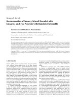
Presbyopia and correction methods
A loss of accommodation with age (>40) to focus on nearby objects
when the crystalline lens becomes harder and loses elasticity and
causes light to focus behind the retina.
Presbyopia correction with spectacles
Presbyopic eye
Retina
/>
Crystalline lens
/>
Spectacles
/>
blur
Contact lens
/>
Surgery
(Effect is not long-lasting)
blur
Progressive addition lens
3
Presbyopia corrections
Multifocal contact lens
•
•
•
•
/>
/>
Multifocal Lasilk
Better vision
More attractive
More convenient (sport activities)
Not be affected by weather conditions
Multifocal CLs for presbyopia
Two vision distances (near and far)
“Image jump”
Focusing various vision distances
within the area of pupil on retina at the
same time (more natural)
Dop=6.0 mm
Power distributions of CLs for presbyopic correction [42-44]
4
6/5/2018
/>
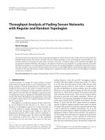
Power profiles of commercial simultaneous multifocal CLs
The power profile of a zonal-aspheric
multifocal CL
[87]
[89]
Additional (Add) powers (low, mid, high) from +0.75 to 3.50 D
5
6/5/2018
Problem statement
• The demand for presbyopia CLs is very high
with more and more requirements.
• None of available multifocal CL designs
presents as the best design.
Lens shapes, materials and manufacture
methods need to be continuously improved.
The Add range of commercial soft multifocal CLs [68]
Smooth connection
Current problems for multifocal CL designs:
• Reduce the dependence of CLs on pupil sizes
• Increase Add powers (>3.5 D)
• Smooth lens surfaces
• Minimal machining errors
6
Curvature continuity ?
Continuity problem of zonal aspheric designs
Research Objectives
Development of a design method of symmetric simultaneous multifocal CLs with:
• Various given smooth power distributions with high Add values
• Uniform optical power in large central zone
• Smooth anterior optical surface profiles with cubic NURBS curves
A comprehensive method from clinical requirements for calculation and output
data for analysis and manufacture.
7
Research summary
Chapter 1
Chapter 2
Design & manufacture method of
multifocal CLs
Chapter 3
Chapter 4
Chapter 6: Conclusion and recommendation
8
Chapter 5
Overview of contact lens design
Contact lens history
10
Contact lens types
RGP contact lens
Soft contact lens
Rigid Gas Permeable (RGP) CLs
•
Better quality of vision
•
More durable
•
Correction of Astigmatism
•
Deposit resistance
•
Less stable
•
Less comfortable, tough adaptation
Scleral contact lens
Soft CLs
•
Very comfortable & easy to adapt
•
Larger & adhere more tight to the cornea
•
No spectacle blur
•
Don’t correct astigmatic error
Fitting areas between CLs and eye (front view) [99]
Hybrid CLs [109]
11
Fitting types of RGP contact lenses
Geometric parameters
Illustration of contact lens for radii and diameters [98]
For multifocal CL design, aspheric, polynomial and freeform curves or surfaces can be used to obtain the
various curvatures of anterior optical surfaces to satisfy non-uniform power profiles.
12
6/5/2018
Aspheric curves
Conventional aspheric function Aspheric curvature
y"
x2 / Ro
y
A2i x2i
k
AS
1 1 (1 kc ) x2 / Ro2 i1
(1 y '2 ) 3/2
kc
Conic curves
kc = 0
Spheres
kc > 0
Oblate ellipses
-1< kc < 0
Prolate ellipses
kc = -1
Parabolic
kc < -1
Hyperbolas
Radius of curvature:
1
RAS
k AS
Center of curvature O(xo, yo)
corresponding to point Q (x,y)
y '(1 y ' )
x
x
o
y"
2
y y 1 y'
o
y"
Conic curves with different conic constants
2
Aspheric design for CLs:
• Clear and sharp images
• Better depth of field
• Thinner
• Low astigmatism
Extended polynomial function
y
x2 / ro
1 1 (1 kc ) x2 / Ro2
13
i
Ax
i
i1
Center of curvature of an point Q on y(x)
An oblate ellipse and its center of
curvature
Freeform surfaces
Optical freeform surfaces
z
( x 2 y 2 ) / Ro
1 1 (1 kc )( x y ) / R
2
2
A base conic
2
o
Ai i ( x, y )
i 1
Orthogonal polynomials
• Zernike polynomial expansion
• Chebyshev polynomial expansion
• Extended Forbes asphere (Q-type)
• -polynomial (Q-polynomial and Zernike polynomial)
Polynomial forms
limitation to present
complex surfaces of
multifocal CLs
• …
Spline functions: B-spline, NURBS
Great flexibility and precision to present freeform shapes
14
6/5/2018
Non Uniform Rational B-spline (NURBS)
NURBS commonly used in CAD, CAM, and CAE for generating
and representing freeform curves and surfaces.
h
NURBS curve: C (u )
N
i 1
h
i, p
N
i 1
(u ) wi Pi
i, p
(u ) wi
where P1 ,P2 ,...,Ph are h control points
w1 , w2 ,..., wh are h weights,
Representation of a semi-circle by a NURBS curve
wth 5 control points
N i , p ( u ) is the i-th B-pline basic function of degree p defined on a knot vector U:
U 0,
..., 0 , u p 2 , ..., u h ,1,
...,1
p 1
p 1
B-spline basic function:
1
Ni,0 (u)
0
Ni, p (u)
15
Three unknown parameters ?
if ui u ui1
• h control points (P)
otherwise
• h weights (w)
u
u
u ui
Ni, p1 (u) i p1
Ni1, p1 (u)
ui p ui
u i p1ui1
• (h-p-1) knots (u)
Center of curvature of NURBS curve
The curvature of an arbitrary point Q on the NURBS curve is:
k (u )
C '(u ) C ''(u )
C '(u )
3
The radius of curvature of point Q is:
R(u)
1
k (u)
Center of curvature of point Q is:
CC ( u ) C ( u ) R ( u ) N ( u )
N(u) is an unit normal vector at point Q:
C '(u) C "(u) C '(u)
N (u)
C '(u) C "(u) C '(u)
16
6/5/2018
Relationship between optical power and cubic NURBS curve
NURBS curve ?
Back vertex power (Pw):
( n 1)ka
Pw (1 n )kb
1
1 tc (1 )ka
n
Unknown
parameter
Given parameters
Anterior surface curvature: ka=1/Ra NURBS curve
17
A. NURBS multifocal CLs with given
optical power distributions
A.1 Functions of three-zone optical power profiles
Pw( x ) Pcenter Add
1
2
x
e
( t )2
2 2
dt
0
Cumulative distribution
function (CDF)
where: xc Wim / 2 and Wim / 6
x: half chord
xc: Center-zone radius
Wim: Intermediate-zone width
Dop: Optical area diameter
Pcenter: Center-power
Add: total additional power (Add=0 Spherical CLs)
sign: “-” for center-near and “+” for center-distance
19
6/5/2018
A.2 Functions of two-zone and one-zone optical power profiles
Two-zone optical power profiles
Pw mod ( x ) Pcenter 2 Add
where:
Dop
2
;
x
1
e
2 0
( t )2
2 2
dt
Dop 2 x c
6
x c Wim Dop / 2
One-zone optical power profiles (Aspheric CLs)
Pw mod ( x ) Pcenter 2 Add
where:
Dop
2
;
x
1
e
2 0
( t )2
2 2
dt
Dop
6
x c 0; Wim Dop / 2
20
6/5/2018
A.3 Optimization problem
Given parameters (clinical requirement)
Back vertex
power of CL
Goal
No. of data points
1/2
m
RMS (Pw i Pw i ) 2 / m ;
i 1
(i 1: m)
m
( n 1)kai
or RMS (1 n )kbi
1
i 1
1 tc (1 )kai
n
ka (u )
Pw
i
i
C '(u ) C ''(u )
C '(u )
3
NURBS curve C(u)
(Three unknown parameters)
21
Min
2
1/2
/ m
Min
Nonlinear
Optimization
Solution:
• Control points
• Weights
• Knots
A.4 Optimization variables and constraints
Table of known and unknowns parameters
Total variables: (4h-p-5)
Constraints:
• Weights 0
• Knots [0 1] and ui
No.
Weights
(positive)
1
w
2
w
3
….
h-p
Control points
Knots
Px
Px1=0
Py
Py1=0
p+2
Px2
Py2=0
w3
up+3
Px3
Py3
…
…
….
…
u
Pxh-p
Pyh-p
Pxh-p+1
Pyh-p+1
w
1
2
h-p
u =..=u
1
u
p+1
=0
h
h-p+1
wh-p+1
uh+1=…uh+p+1=1
…
…
…
…
h-1
wh-1
Pxh-1
Pyh-1
h
w
Pxh=Dop/2
Pyh
h
P1P2 // OX
22
Dop/2
C5. Optimization by Simulated Annealing algorithm
Initial conditions: X0, T0,
Functions:FObj, g(T,k), q(L,k), N(X)
Stop conditions: Tmin, Max_Iter,
k=0, Iter=0, L0 , i=0
Objective function:
1/2
FObj
m
(Pw i Pw i ) 2 / m
i 1
Lk+1=q(L,k)
Neighborhood function:
N(X
i
k 1
∆F Fi+1-Fi
Metropolis criteria
) X (UB - LB )
i
k
i
i
i
Cooling function:
i
0
23
N
Ti+1 Tmin
i 1/ Dv
N
e( F / kBTk ) Rand (0,1)
∆F 0
Y
Xcurrent=Xi+1
Fcurrent=Fobj(Xcurrent)
Y
N
i Lk
Y
Iter Iter+i
k=k+1
i=0
OUTER LOOPS
Fi+1
N
Tk+1=g(T,k)
Iterations of inner loops: q( L, k ) Lk
Initial solutions:
Y
N
Reducing temperature
g(T , k ) T exp c k
i
i=i+1
Xi+1=N(Xi)
Fi+1=Fobj(Xi+1)
INNER LOOPS
N
Iter Max_Iter
Y
STOP
Y
A.5 Case study: Four PMMA multifocal CL designs
Table of given parameters
Case
Center
power
(D)
Add
powers
(D)
Base
curves
(mm)
Overall
diameters
(mm)
Dop
(mm)
1
-2.5
(CN)
5.0
7.5
10.5
6.0
2
-4.0
(CD)
5 .0
7.5
10.5
3
-4.0
(CD)
5 .0
7.5
4
-2.0
(CN)
5.0
7.5
Note: CN: center-near; CD: center-distance
Generation of
power profiles
tc
xc
(mm)
Wim
(mm)
0.14
0
3
6.0
0.14
0
3
10.5
6.0
0.14
1.4
1.6
Two-zone optical power profile
10.5
6.0
0.14
0.8
1.2
Three-zone optical power profile
(mm)
One-zone optical power profiles
The refractive index of PMMA: n=1.49
Optimization of
NURBS curves
Large central zone
24
A.7 Optimized parameters of NURBS curves
Results of Case 1
Selection of number control points
No.
In consideration of No. of variables, 9 control
points are used for all designs
NURBS curve vs Extended polynomial
25
1
2
3
4
5
6
7
8
9
10
11
12
13
…
200
201
Higher precision and flexibility
Weights
w
1.00400
1.00183
0.99824
0.99561
0.99434
0.99515
0.99829
1.00245
1.00511
Knot vector
U
0.00000
0.00000
0.00000
0.00000
0.16696
0.33801
0.50000
0.66092
0.83141
1.00000
1.00000
1.00000
1.00000
Control points
Px
Py
0.00000
0.00000
0.16464
0.00000
0.50039
-0.01059
1.00112
-0.05910
1.49791
-0.13997
1.99417
-0.25331
2.49505
-0.40228
2.83281
-0.52710
3.00000
-0.59496
Other cases in Appendix B
NURBS curve
Cx
Cy
0.00000
0.00000
0.01488
-1.4E-05
0.02976
-5.7E-05
0.0447
-1.3E-04
0.05954
-2.3E-04
0.07443
-3.6E-04
0.08932
- 5.1E-04
0.10422
-7.0E-04
0.11912
-9.1 E-04
0.13402
0.13402
0.14892
0.14892
0.16383
0.16383
0.17874
0.17874
…
…
2.98471
-0.58987
3.00000
-0.59610