BÀI TẬP ARDUNIO CƠ BẢN ĐẾN NÂNG CAO
Bạn đang xem bản rút gọn của tài liệu. Xem và tải ngay bản đầy đủ của tài liệu tại đây (2.94 MB, 97 trang )
1.
ATmega168/328-Arduino Pin Mapping .................................................................................................. 2
2.
Blink Led – Turn a LED on and off – Digital out.................................................................................... 3
3.
Blink Without Delay - Blink an LED without using the delay() function – Digital out .......................... 4
4.
Button – Input Pullup Serial - Demonstrates the use of INPUT_PULLUP with pinMode(). ................. 6
5.
Button - Digital Read Serial - Read a switch, print the state out to the Arduino Serial Monitor ............ 9
6.
Button – Digital input - Use a pushbutton to control an LED ............................................................... 11
7.
Button – Debounce - Read a pushbutton, filtering noise ....................................................................... 13
8.
Button – State Change Detection (Edge Detection) for pushbuttons – Digital input & output ............. 15
9.
Analog Input Pins................................................................................................................................... 17
10.
Analog Input – Variable Resistor or Photoresistor ............................................................................ 18
11. Analog Read Serial, Read Analog Voltage - Read a potentiometer, print its state out to the Arduino
Serial Monitor ............................................................................................................................................... 21
12. Analog In, Out Serial - Read an analog input pin, map the result, and then use that data to dim or
brighten an LED. ........................................................................................................................................... 23
13.
Calibration - Define a maximum and minimum for expected analog sensor values ......................... 26
14.
Fading - Use an analog output (PWM pin) to fade an LED. .............................................................. 30
15.
Connect and use an RGB LED with an Arduino................................................................................ 33
16.
RGB LED – analog output ................................................................................................................. 36
17.
Arduino 8 bit Binary LED Counter .................................................................................................... 43
18.
8 More LEDs ...................................................................................................................................... 46
19.
Serial to Parallel Shifting-Out with a 74HC595 ................................................................................. 50
20.
Smoothing - Smooth multiple readings of an analog input ................................................................ 69
21.
7 Segment Display On Arduino ......................................................................................................... 74
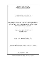
1. ATmega168/328-Arduino Pin Mapping
Note that this chart is for the DIP-package chip. The Arduino Mini is based upon a smaller physical IC
package that includes two extra ADC pins, which are not available in the DIP-package Arduino
implementations.
2. Blink Led – Turn a LED on and off – Digital out
Hardware Required
Arduino or Genuino Board
LED
220 ohm resistor
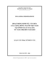
Circuit
To build the circuit, connect one end of the resistor to Arduino pin 13. Connect the long leg of the LED (the
positive leg, called the anode) to the other end of the resistor. Connect the short leg of the LED (the negative
leg, called the cathode) to the Arduino GND.
Most Arduino boards already have an LED attached to pin 13 on the board itself. If you run this example
with no hardware attached, you should see that LED blink.
Figure 1: Led circuit
Code
int pin = 13;
// the setup function runs once when you press reset or power the board
void setup() {
// initialize digital pin 13 as an output.
pinMode(pin, OUTPUT);
}
// the loop function runs over and over again forever
void loop() {
digitalWrite(pin, HIGH);
// turn the LED on (HIGH is the voltage level)
delay(500);
// wait for a second
digitalWrite(pin, LOW);
// turn the LED off by making the voltage LOW
delay(5000);
// wait for a second
}
3. Blink Without Delay - Blink an LED without using the delay() function – Digital out
Sometimes you need to do two things at once. For example you might want to blink an LED while reading a
button press. In this case, you can't use delay(), because Arduino pauses your program during the delay().
If the button is pressed while Arduino is paused waiting for the delay() to pass, your program will miss the
button press.
This sketch demonstrates how to blink an LED without using delay(). It turns the LED on and then makes
note of the time. Then, each time through loop(), it checks to see if the desired blink time has passed. If it
has, it toggles the LED on or off and makes note of the new time. In this way the LED blinks continuously
while the sketch execution never lags on a single instruction.
An analogy would be warming up a pizza in your microwave, and also waiting some important email. You
put the pizza in the microwave and set it for 10 minutes. The analogy to using delay() would be to sit in
front of the microwave watching the timer count down from 10 minutes until the timer reaches zero. If the
important email arrives during this time you will miss it.
What you would do in real life would be to turn on the pizza, and then check your email, and then maybe do
something else (that doesn't take too long!) and every so often you will come back to the microwave to see if
the timer has reached zero, indicating that your pizza is done.
In this tutorial you will learn how to set up a similar timer.
Hardware Required
Arduino or Genuino Board
LED
220 ohm resistor
Circuit
Use the circuit in Figure 1: Led circuit
Code
// constants won't change. Used here to set a pin number :
const int ledPin = 13;
// the number of the LED pin
// Variables will change :
int ledState = LOW;
// ledState used to set the LED
// Generally, you should use "unsigned long" for variables that hold time
// The value will quickly become too large for an int to store
unsigned long previousMillis = 0;
// will store last time LED was updated
// constants won't change :
const long interval = 1000;
// interval at which to blink (milliseconds)
void setup() {
// set the digital pin as output:
pinMode(ledPin, OUTPUT);
}
void loop()
{
// here is where you'd put code that needs to be running all the time.
// check to see if it's time to blink the LED; that is, if the
// difference between the current time and last time you blinked
// the LED is bigger than the interval at which you want to
// blink the LED.
unsigned long currentMillis = millis();
if(currentMillis - previousMillis >= interval) {
// save the last time you blinked the LED
previousMillis = currentMillis;
// if the LED is off turn it on and vice-versa:
if (ledState == LOW)
ledState = HIGH;
else
ledState = LOW;
// set the LED with the ledState of the variable:
digitalWrite(ledPin, ledState);
}
}
4. Button – Input Pullup Serial - Demonstrates the use of INPUT_PULLUP with
pinMode().
This example demonstrates the use of INPUT_PULLUP with pinMode(). It monitors the state of a switch by
establishing serial communication between your Arduino and your computer over USB.
Additionally, when the input is HIGH, the onboard LED attached to pin 13 will turn on; when LOW, the
LED will turn off.
Hardware Required
Arduino Board
A momentary switch, button, or toggle switch
breadboard
hook-up wire
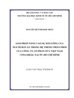
Circuit
Figure 2: Button circuit
Connect two wires to the Arduino board. The black wire connects ground to one leg of the pushbutton. The
second wire goes from digital pin 2 to the other leg of the pushbutton.
Pushbuttons or switches connect two points in a circuit when you press them. When the pushbutton is open
(unpressed) there is no connection between the two legs of the pushbutton. Because the internal pull-up on
pin 2 is active and connected to 5V, we read HIGH when the button is open. When the button is closed, the
Arduino reads LOW because a connection to ground is completed.
Code
In the program below, the very first thing that you do will in the setup function is to begin serial
communications, at 9600 bits of data per second, between your Arduino and your computer with the line:
Serial.begin(9600);
Next, initialize digital pin 2 as an input with the internal pull-up resistor enabled:
pinMode(2,INPUT_PULLUP);
The following line make pin 13, with the onboard LED, an output :
pinMode(13, OUTPUT);
Now that your setup has been completed, move into the main loop of your code. When your button is not
pressed, the internal pull-up resistor connects to 5 volts. This causes the Arduino to report "1" or HIGH.
When the button is pressed, the Arduino pin is pulled to ground, causing the Arduino report a "0", or LOW.
The first thing you need to do in the main loop of your program is to establish a variable to hold the
information coming in from your switch. Since the information coming in from the switch will be either a "1"
or a "0", you can use an int datatype. Call this variable sensorValue, and set it to equal whatever is being
read on digital pin 2. You can accomplish all this with just one line of code:
int sensorValue = digitalRead(2);
Once the Arduino has read the input, make it print this information back to the computer as a decimal (DEC)
value. You can do this with the command Serial.println() in our last line of code:
Serial.println(sensorValue, DEC);
Now, when you open your Serial Monitor in the Arduino environment, you will see a stream of "0"s if your
switch is closed, or "1"s if your switch is open.
The LED on pin 13 will illuminate when the switch is HIGH, and turn off when LOW.
void setup() {
//start serial connection
Serial.begin(9600);
//configure pin2 as an input and enable the internal pull-up resistor
pinMode(2, INPUT_PULLUP);
pinMode(13, OUTPUT);
}
void loop() {
//read the pushbutton value into a variable
int sensorVal = digitalRead(2);
//print out the value of the pushbutton
Serial.println(sensorVal);
// Keep in mind the pullup means the pushbutton's
// logic is inverted. It goes HIGH when it's open,
// and LOW when it's pressed. Turn on pin 13 when the
// button's pressed, and off when it's not:
if (sensorVal == HIGH) {
digitalWrite(13, LOW);
}
else {
digitalWrite(13, HIGH);
}
}
5. Button - Digital Read Serial - Read a switch, print the state out to the Arduino Serial
Monitor
This example shows you how to monitor the state of a switch by establishing serial communication between
your Arduino or Genuino and your computer over USB.
Hardware Required
Arduino or Genuino Board
A momentary switch, button, or toggle switch
10k ohm resistor
hook-up wires
breadboard
Circuit
Code
In the program below, the very first thing that you do will in the setup function is to begin serial
communications, at 9600 bits of data per second, between your board and your computer with the line:
Serial.begin(9600);
Next, initialize digital pin 2, the pin that will read the output from your button, as an input:
pinMode(2,INPUT);
Now that your setup has been completed, move into the main loop of your code. When your button is
pressed, 5 volts will freely flow through your circuit, and when it is not pressed, the input pin will be
connected to ground through the 10k ohm resistor. This is a digital input, meaning that the switch can only be
in either an on state (seen by your Arduino as a "1", or HIGH) or an off state (seen by your Arduino as a "0",
or LOW), with nothing in between.
The first thing you need to do in the main loop of your program is to establish a variable to hold the
information coming in from your switch. Since the information coming in from the switch will be either a "1"
or a "0", you can use an int datatype. Call this variable sensorValue, and set it to equal whatever is being
read on digital pin 2. You can accomplish all this with just one line of code:
int sensorValue = digitalRead(2);
Once the bord has read the input, make it print this information back to the computer as a decimal value. You
can do this with the command Serial.println() in our last line of code:
Serial.println(sensorValue);
Now, when you open your Serial Monitor in the Arduino Software (IDE), you will see a stream of "0"s if
your switch is open, or "1"s if your switch is closed.
// digital pin 2 has a pushbutton attached to it. Give it a name:
int pushButton = 2;
// the setup routine runs once when you press reset:
void setup() {
// initialize serial communication at 9600 bits per second:
Serial.begin(9600);
// make the pushbutton's pin an input:
pinMode(pushButton, INPUT);
}
// the loop routine runs over and over again forever:
void loop() {
// read the input pin:
int buttonState = digitalRead(pushButton);
// print out the state of the button:
Serial.println(buttonState);
delay(1);
// delay in between reads for stability
}
6. Button – Digital input - Use a pushbutton to control an LED
Pushbuttons or switches connect two points in a circuit when you press them. This example turns on the
built-in LED on pin 13 when you press the button.
Hardware
Arduino or Genuino Board
Momentary button or Switch
220 ohm, 10K ohm resistor
hook-up wires
breadboard
LED
Circuit
LED circuit: Connect LED as in 2. or you can use the LED available for pin 13.
Button circuit:
Connect three wires to the board. The first two, red and black, connect to the two long vertical rows on the
side of the breadboard to provide access to the 5 volt supply and ground. The third wire goes from digital pin
2 to one leg of the pushbutton. That same leg of the button connects through a pull-down resistor (here 10K
ohm) to ground. The other leg of the button connects to the 5 volt supply.
When the pushbutton is open (unpressed) there is no connection between the two legs of the pushbutton, so
the pin is connected to ground (through the pull-down resistor) and we read a LOW. When the button is
closed (pressed), it makes a connection between its two legs, connecting the pin to 5 volts, so that we read a
HIGH.
You can also wire this circuit the opposite way, with a pullup resistor keeping the input HIGH, and going
LOW when the button is pressed. If so, the behavior of the sketch will be reversed, with the LED normally
on and turning off when you press the button.
If you disconnect the digital I/O pin from everything, the LED may blink erratically. This is because the
input is "floating" - that is, it will randomly return either HIGH or LOW. That's why you need a pull-up or
pull-down resistor in the circuit.
Code
const int buttonPin = 2;
const int ledPin = 13;
int buttonState = 0;
// the setup routine runs once when you press reset:
void setup() {
// declare pin 9 to be an output:
pinMode(ledPin, OUTPUT);
pinMode(buttonPin, INPUT);
}
// the loop routine runs over and over again forever:
void loop() {
buttonState = digitalRead(buttonPin);
if (buttonState == HIGH){
digitalWrite(ledPin, HIGH);
}
else {
digitalWrite(ledPin, LOW);
}
}
Tweaking
- Đổi sao cho khi nhấn thì LED tắt, thả thì LED sáng
C1: Reverse HIGH to LOW to revert the state
C2: đổi cực của mạch trên
Instead of connecting pin 2 to a resistor and then GND, connect that resistor to 5V and move the GND wire
to the other side of the button
7. Button – Debounce - Read a pushbutton, filtering noise
Pushbuttons often generate spurious open/close transitions when pressed, due to mechanical and physical
issues: these transitions may be read as multiple presses in a very short time fooling the program. This
example demonstrates how to debounce an input, which means checking twice in a short period of time to
make sure the pushbutton is definitely pressed. Without debouncing, pressing the button once may cause
unpredictable results. This sketch uses the millis() function to keep track of the time passed since the
button was pressed.
Circuit
Like 3b
Code
The sketch below is based on Limor Fried's version of debounce, but the logic is inverted from her
example. In her example, the switch returns LOW when closed, and HIGH when open. Here, the switch
returns HIGH when pressed and LOW when not pressed.
// constants won't change. They're used here to
// set pin numbers:
const int buttonPin = 2;
// the number of the pushbutton pin
const int ledPin = 13;
// the number of the LED pin
// Variables will change:
int ledState = HIGH;
int buttonState;
int lastButtonState = LOW;
// the current state of the output pin
// the current reading from the input pin
// the previous reading from the input pin
// the following variables are long's because the time, measured in miliseconds,
// will quickly become a bigger number than can be stored in an int.
long lastDebounceTime = 0; // the last time the output pin was toggled
long debounceDelay = 50;
// the debounce time; increase if the output flickers
void setup() {
pinMode(buttonPin, INPUT);
pinMode(ledPin, OUTPUT);
// set initial LED state
digitalWrite(ledPin, ledState);
}
void loop() {
// read the state of the switch into a local variable:
int reading = digitalRead(buttonPin);
// check to see if you just pressed the button
// (i.e. the input went from LOW to HIGH), and you've waited
// long enough since the last press to ignore any noise:
// If the switch changed, due to noise or pressing:
if (reading != lastButtonState) {
// reset the debouncing timer
lastDebounceTime = millis();
}
if ((millis() - lastDebounceTime) > debounceDelay) {
// whatever the reading is at, it's been there for longer
// than the debounce delay, so take it as the actual current state:
// if the button state has changed:
if (reading != buttonState) {
buttonState = reading;
// only toggle the LED if the new button state is HIGH
if (buttonState == HIGH) {
ledState = !ledState;
}
}
}
// set the LED:
digitalWrite(ledPin, ledState);
// save the reading. Next time through the loop,
// it'll be the lastButtonState:
lastButtonState = reading;
}
8. Button – State Change Detection (Edge Detection) for pushbuttons – Digital input &
output
Once you've got a pushbutton working, you often want to do some action based on how many times the
button is pushed. To do this, you need to know when the button changes state from off to on, and count how
many times this change of state happens. This is called state change detection or edge detection. In this
tutorial we learn how to check the state change, we send a message to the Serial Monitor with the relevant
information and we count four state changes to turn on and off an LED.
Circuit
Like 3b
Code
The sketch below continually reads the button's state. It then compares the button's state to its state the last
time through the main loop. If the current button state is different from the last button state and the current
button state is high, then the button changed from off to on. The sketch then increments a button push
counter.
The sketch also checks the button push counter's value, and if it's an even multiple of four, it turns the LED
on pin 13 ON. Otherwise, it turns it off.
// this constant won't change:
const int buttonPin = 2;
// the pin that the pushbutton is attached to
const int ledPin = 13;
// the pin that the LED is attached to
// Variables will change:
int buttonPushCounter = 0;
int buttonState = 0;
int lastButtonState = 0;
// counter for the number of button presses
// current state of the button
// previous state of the button
void setup() {
// initialize the button pin as a input:
pinMode(buttonPin, INPUT);
// initialize the LED as an output:
pinMode(ledPin, OUTPUT);
// initialize serial communication:
Serial.begin(9600);
}
void loop() {
// read the pushbutton input pin:
buttonState = digitalRead(buttonPin);
// compare the buttonState to its previous state
if (buttonState != lastButtonState) {
// if the state has changed, increment the counter
if (buttonState == HIGH) {
// if the current state is HIGH then the button
// wend from off to on:
buttonPushCounter++;
Serial.println("on");
Serial.print("number of button pushes: ");
Serial.println(buttonPushCounter);
}
else {
// if the current state is LOW then the button
// wend from on to off:
Serial.println("off");
}
// Delay a little bit to avoid bouncing
delay(50);
}
// save the current state as the last state,
//for next time through the loop
lastButtonState = buttonState;
//
//
//
//
if
turns on the LED every four button pushes by
checking the modulo of the button push counter.
the modulo function gives you the remainder of
the division of two numbers:
(buttonPushCounter % 4 == 0) {
digitalWrite(ledPin, HIGH);
} else {
digitalWrite(ledPin, LOW);
}
}
9. Analog Input Pins
A description of the analog input pins on an Arduino chip (Atmega8, Atmega168, Atmega328, or
Atmega1280).
A/D converter
The Atmega controllers used for the Arduino contain an onboard 6 channel analog-to-digital (A/D) converter.
The converter has 10 bit resolution, returning integers from 0 to 1023. While the main function of the analog
pins for most Arduino users is to read analog sensors, the analog pins also have all the functionality of
general purpose input/output (GPIO) pins (the same as digital pins 0 - 13).
Consequently, if a user needs more general purpose input output pins, and all the analog pins are not in use,
the analog pins may be used for GPIO.
Pin mapping
The analog pins can be used identically to the digital pins, using the aliases A0 (for analog input 0), A1, etc.
For example, the code would look like this to set analog pin 0 to an output, and to set it HIGH:
pinMode(A0, OUTPUT);
digitalWrite(A0, HIGH);
Pullup resistors
The analog pins also have pullup resistors, which work identically to pullup resistors on the digital pins. They
are enabled by issuing a command such as
digitalWrite(A0, HIGH);
// set pullup on analog pin 0
while the pin is an input.
Be aware however that turning on a pullup will affect the values reported by analogRead().
Details and Caveats
The analogRead command will not work correctly if a pin has been previously set to an output, so if this is
the case, set it back to an input before using analogRead. Similarly if the pin has been set to HIGH as an
output, the pullup resistor will be set, when switched back to an input.
The Atmega datasheet also cautions against switching analog pins in close temporal proximity to making
A/D readings (analogRead) on other analog pins. This can cause electrical noise and introduce jitter in the
analog system. It may be desirable, after manipulating analog pins (in digital mode), to add a short delay
before using analogRead() to read other analog pins.
10.
Analog Input – Variable Resistor or Photoresistor
In this example we use a variable resistor (a potentiometer or a photoresistor), we read its value using one
analog input of an Arduino or Genuino board and we change the blink rate of the built-in LED accordingly.
The resistor's analog value is read as a voltage because this is how the analog inputs work.
Hardware Required
Arduino or Genuino Board
Potentiometer or
10K ohm photoresistor and 10K ohm resistor
built-in LED on pin 13 or
220 ohm resistor and red LED
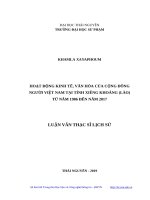
Circuit
With a photoresistor
Connect three wires to the Arduino or Genuino board. The first goes to ground from one of the outer pins of
the potentiometer. The second goes from 5 volts to the other outer pin of the potentiometer. The third goes
from analog input 0 to the middle pin of the potentiometer.
For this example, it is possible to use the board's built in LED attached to pin 13. To use an additional LED,
attach its longer leg (the positive leg, or anode), to digital pin 13 in series with the 220 ohm resistor, and it's
shorter leg (the negative leg, or cathode) to the ground (GND) pin next to pin 13.
The circuit based on a photoresistor uses a resistor divider to allow the high impedence Analog input to
measure the voltage. These inputs do not draw almost any current, therefore by Ohm's law the voltage
measured on the other end of a resistor connected to 5V is always 5V, regardless the resistor's value. To get a
voltage proportional to the photoresistor value, a resistor divider is necessary. This circuit uses a variable
resistor, a fixed resistor and the measurement point is in the middle of the resistors. The voltage measured
(Vout) follows this formula:
Vout=Vin*(R2/(R1+R2))
where Vin is 5V, R2 is 10k ohm and R1 is the photoresistor value that ranges from 1M ohm in darkness to
10k ohm in daylight (10 lumen) and less than 1k ohm in bright light or sunlight (>100 lumen).
Code
At the beginning of this sketch, the variable sensorPin is set to to analog pin 0, where your potentiometer is
attached, and ledPin is set to digital pin 13. You'll also create another variable, sensorValue to store the
values read from your sensor.
The analogRead() command converts the input voltage range, 0 to 5 volts, to a digital value between 0 and
1023. This is done by a circuit inside the microcontroller called an analog-to-digital converter or ADC.
By turning the shaft of the potentiometer, you change the amount of resistance on either side of the center pin
(or wiper) of the potentiometer. This changes the relative resistances between the center pin and the two
outside pins, giving you a different voltage at the analog input. When the shaft is turned all the way in one
direction, there is no resistance between the center pin and the pin connected to ground. The voltage at the
center pin then is 0 volts, and analogRead() returns 0. When the shaft is turned all the way in the other
direction, there is no resistance between the center pin and the pin connected to +5 volts. The voltage at the
center pin then is 5 volts, and analogRead() returns 1023. In between, analogRead() returns a number
between 0 and 1023 that is proportional to the amount of voltage being applied to the pin.
That value, stored in sensorValue, is used to set a delay() for your blink cycle. The higher the value, the
longer the cycle, the smaller the value, the shorter the cycle. The value is read at the beginning of the cycle,
therefore the on/off time is always equal.
int sensorPin = A0;
int ledPin = 13;
int sensorValue = 0;
// select the input pin for the potentiometer
// select the pin for the LED
// variable to store the value coming from the sensor
void setup() {
// declare the ledPin as an OUTPUT:
pinMode(ledPin, OUTPUT);
}
void loop() {
// read the value from the sensor:
sensorValue = analogRead(sensorPin);
// turn the ledPin on
digitalWrite(ledPin, HIGH);
// stop the program for <sensorValue> milliseconds:
delay(sensorValue);
// turn the ledPin off:
digitalWrite(ledPin, LOW);
// stop the program for for <sensorValue> milliseconds:
delay(sensorValue);
}
Tweaking
By putting an if statement around the digitalWrite part of the loop, you are able to set a threshold.
void loop() {
// read the value from the sensor:
sensorValue = analogRead(sensorPin);
if (sensorValue > 511){
// turn the ledPin on
digitalWrite(ledPin, HIGH);
// stop the program for <sensorValue> milliseconds:
delay(sensorValue);
// turn the ledPin off:
digitalWrite(ledPin, LOW);
// stop the program for for <sensorValue> milliseconds:
delay(sensorValue);
}
}
11. Analog Read Serial, Read Analog Voltage - Read a potentiometer, print its state out
to the Arduino Serial Monitor
This example shows you how to read analog input from the physical world using a potentiometer. A
potentiometer is a simple mechanical device that provides a varying amount of resistance when its shaft is
turned. By passing voltage through a potentiometer and into an analog input on your board, it is possible to
measure the amount of resistance produced by a potentiometer (or pot for short) as an analog value. In this
example you will monitor the state of your potentiometer after establishing serial communication between
your Arduino or Genuino and your computer running the Arduino Software (IDE).
Hardware Required
Arduino or Genuino Board
10k ohm Potentiometer
Circuit
Connect the three wires from the potentiometer to your board. The first goes from one of the outer pins of the
potentiometerto ground . The second goes from the other outer pin of the potentiometer to 5 volts. The third
goes from the middle pin of the potentiometer to the analog pin A0.
By turning the shaft of the potentiometer, you change the amount of resistance on either side of the wiper,
which is connected to the center pin of the potentiometer. This changes the voltage at the center pin. When
the resistance between the center and the side connected to 5 volts is close to zero (and the resistance on the
other side is close to 10k ohm), the voltage at the center pin nears 5 volts. When the resistances are reversed,
the voltage at the center pin nears 0 volts, or ground. This voltage is the analog voltage that you're reading as
an input.
The Arduino and Genuino boards have a circuit inside called an analog-to-digital converter or ADC that
reads this changing voltage and converts it to a number between 0 and 1023. When the shaft is turned all the
way in one direction, there are 0 volts going to the pin, and the input value is 0. When the shaft is turned all
the way in the opposite direction, there are 5 volts going to the pin and the input value is 1023. In between,
analogRead() returns a number between 0 and 1023 that is proportional to the amount of voltage being
applied to the pin.
Code
In the sketch below, the only thing that you do in the setup function is to begin serial communications, at
9600 bits of data per second, between your board and your computer with the command:
Serial.begin(9600);
Next, in the main loop of your code, you need to establish a variable to store the resistance value (which will
be between 0 and 1023, perfect for an int datatype) coming in from your potentiometer:
int sensorValue = analogRead(A0);
Finally, you need to print this information to your serial monitor window. You can do this with the command
Serial.println() in your last line of code:
Serial.println(sensorValue)
Now, when you open your Serial Monitor in the Arduino Software (IDE) (by clicking the icon that looks like
a lens, on the right, in the green top bar or using the keyboard shortcut Ctrl+Shift+M), you should see a
steady stream of numbers ranging from 0-1023, correlating to the position of the pot. As you turn your
potentiometer, these numbers will respond almost instantly.
// the setup routine runs once when you press reset:
void setup() {
// initialize serial communication at 9600 bits per second:
Serial.begin(9600);
}
// the loop routine runs over and over again forever:
void loop() {
// read the input on analog pin 0:
int sensorValue = analogRead(A0);
// print out the value you read:
Serial.println(sensorValue);
delay(1);
// delay in between reads for stability
}
Tweaking
To change the values from 0-1023 to a range that corresponds to the voltage the pin is reading, you'll need to
create another variable, a float, and do a little math. To scale the numbers between 0.0 and 5.0, divide 5.0
by 1023.0 and multiply that by sensorValue :
float voltage= sensorValue * (5.0 / 1023.0);
12. Analog In, Out Serial - Read an analog input pin, map the result, and then use that
data to dim or brighten an LED.
This example shows you how to read an analog input pin, map the result to a range from 0 to 255, use that
result to set the pulse width modulation (PWM) of an output pin to dim or brighten an LED and print the
values on the serial monitor of the Arduino Software (IDE).
Hardware Required
Arduino or Genuino Board
Potentiometer
Red LED
220 ohm resistor
Circuit
Connect one pin from your pot to 5V, the center pin to analog pin 0 and the remaining pin to ground. Next,
connect a 220 ohm current limiting resistor to digital pin 9, with an LED in series. The long, positive leg (the
anode) of the LED should be connected to the output from the resistor, with the shorter, negative leg (the
cathode) connected to ground.
Code
In the sketch below, after declaring two pin assignments (analog 0 for our potentiometer and digital 9 for
your LED) and two variables, sensorValue and outputValue, the only things that you do in the setup()
function is to begin serial communication.
Next, in the main loop, sensorValue is assigned to store the raw analog value read from the potentiometer.
Arduino has an analogRead range from 0 to 1023, and an analogWrite range only from 0 to 255, therefore
the data from the potentiometer needs to be converted to fit into the smaller range before using it to dim the
LED.
In order to convert this value, use a function called map():
outputValue = map(sensorValue, 0, 1023, 0, 255);
outputValue
is assigned to equal the scaled value from the potentiometer. map() accepts five arguments:
The value to be mapped, the low range and high values of the input data, and the low and high values for that
data to be remapped to. In this case, the sensor data is mapped down from its original range of 0 to 1023 to 0
to 255.
The newly mapped sensor data is then output to the analogOutPin dimming or brightening the LED as the
potentiometer is turned. Finally, both the raw and scaled sensor values are sent to the Arduino Software
(IDE) serial monitor window, in a steady stream of data.
// These constants won't change. They're used to give names
// to the pins used:
const int analogInPin = A0; // Analog input pin that the potentiometer is attached to
const int analogOutPin = 9; // Analog output pin that the LED is attached to
int sensorValue = 0;
int outputValue = 0;
// value read from the pot
// value output to the PWM (analog out)
void setup() {
// initialize serial communications at 9600 bps:
Serial.begin(9600);
}
void loop() {
// read the analog in value:
sensorValue = analogRead(analogInPin);
// map it to the range of the analog out:
outputValue = map(sensorValue, 0, 1023, 0, 255);
// change the analog out value:
analogWrite(analogOutPin, outputValue);
// print the results to the serial monitor:
Serial.print("sensor = " );
Serial.print(sensorValue);
Serial.print("\t output = ");
Serial.println(outputValue);
// wait 2 milliseconds before the next loop
// for the analog-to-digital converter to settle
// after the last reading:
delay(2);
}