steel buildings in europe single - storey steel building p06 Detailed design of built up columns
Bạn đang xem bản rút gọn của tài liệu. Xem và tải ngay bản đầy đủ của tài liệu tại đây (309.55 KB, 41 trang )
STEEL BUILDINGS IN EUROPE
Single-Storey Steel Buildings
Part 6: Detailed Design of
Built-up Columns
Single-Storey Steel Buildings
Part 6: Detailed Design of
Built-up Columns
6 - ii
Part 6: Detailed Design of Built-up Columns
FOREWORD
This publication is part six of the design guide, Single-Storey Steel Buildings.
The 11 parts in the Single-Storey Steel Buildings guide are:
Part 1:
Part 2:
Part 3:
Part 4:
Part 5:
Part 6:
Part 7:
Part 8:
Part 9:
Part 10:
Part 11:
Architect’s guide
Concept design
Actions
Detailed design of portal frames
Detailed design of trusses
Detailed design of built-up columns
Fire engineering
Building envelope
Introduction to computer software
Model construction specification
Moment connections
Single-Storey Steel Buildings is one of two design guides. The second design guide is
Multi-Storey Steel Buildings.
The two design guides have been produced in the framework of the European project
“Facilitating the market development for sections in industrial halls and low rise
buildings (SECHALO) RFS2-CT-2008-0030”.
The design guides have been prepared under the direction of Arcelor Mittal, Peiner
Träger and Corus. The technical content has been prepared by CTICM and SCI,
collaborating as the Steel Alliance.
6 - iii
Part 6: Detailed Design of Built-up Columns
6 - iv
Part 6: Detailed Design of Built-up Columns
Contents
Page No
FOREWORD
iii
SUMMARY
vi
1
INTRODUCTION
1
2
TYPES OF BUILT-UP MEMBERS AND THEIR APPLICATION
2.1 General
2.2 Laced built-up columns
2.3 Battened built-up columns
2
2
5
7
3
DETAILED CALCULATIONS
3.1 General
3.2 Design methodology for laced built-up columns
3.3 Design methodology for battened built-up columns
3.4 Buckling length
REFERENCES
APPENDIX A
9
9
9
14
17
19
Worked Example: Design of a laced built-up column
6-v
21
Part 6: Detailed Design of Built-up Columns
SUMMARY
This guide covers the structural arrangements and the calculations for built-up columns
fabricated from hot rolled sections.
The calculations refer to the European Standard EN 1993-1-1, with complementary
information where necessary.
The design procedures of EN 1993-1-1 are presented to verify a built-up column with
lacing or battening using simplified equations and formulas.
A worked example is given in Appendix A.
6 - vi
Part 6: Detailed Design of Built-up Columns
1
INTRODUCTION
Built-up columns are used in steel construction when the column buckling
lengths are large and the compression forces are relatively low. This guide
covers two types of built-up columns:
Built-up columns with lacing
Built-up columns with battens.
This document includes an overview of common details for such members. It
describes the design method according to EN 1993-1-1[1] for the determination
of the internal forces and the buckling resistance of each member (chords,
diagonals, etc) of built-up columns made of hot rolled profiles.
It should be noted that due to the shear deformation, battened built-up columns
are more flexible than solid columns with the same inertia; this must be taken
into account in the design.
In order to derive the axial resistance of a steel built-up column, the following
must be addressed:
Analysis of the built-up column to determine the internal forces by taking
into account an equivalent initial imperfection and the second order effects
Verification of the chords and bracing members (diagonals and battens)
Verification of the connections.
A fully worked example of a built-up column with an N-shape arrangement of
lacings is given in Appendix A, which illustrates the design principles.
6-1
Part 6: Detailed Design of Built-up Columns
2
TYPES OF BUILT-UP MEMBERS AND THEIR
APPLICATION
2.1
General
In general, built-up columns are used in industrial buildings, either as posts for
cladding when their buckling length is very long, or as columns supporting a
crane girder.
When used as a post for cladding with pinned ends, the column is designed to
support the horizontal forces, mainly due to wind. Hence the bending moment
in such a built-up column is predominant compared to the compression force.
Figure 2.1
Post for cladding with pinned ends
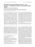
A typical built-up column that supports a crane girder is shown in Figure 2.2.
They usually have a fixed base and a pinned end at the top, and are designed to
resist:
The compression forces that result either from the frame or from the crane
rail
The horizontal forces that result from the effects of the crane applied on the
internal chord and the wind loads applied to the external one.
In this case, the compression forces are predominant compared to the bending
moment.
6-2
Part 6: Detailed Design of Built-up Columns
1N
Ed
= 900 kN
MEd = 450 kNm
1
Crane girder
Figure 2.2
Built-up column supporting a crane girder
The built-up columns are composed of two parallel chords interconnected by
lacings or battens – see Figure 2.1. In general, the truss system concentrates
material at the structurally most efficient locations for force transfer.
In an industrial building and for a given height, built up columns theoretically
have the least steel weight of any steel framing system.
Any hot rolled section can be used for the chords and the web members of
built-up columns. However, channels or I-sections are most commonly used as
chords. Their combination with angles presents a convenient technical solution
for built-up columns with lacing or battens. Flat bars are also used in built-up
column as battens.
This guide covers two types of built-up columns with pinned ends that are
assumed to be laterally supported:
Laced columns
Battened columns.
6-3
Part 6: Detailed Design of Built-up Columns
Laced column
Figure 2.3
Battened column
Built-up columns
The difference between these two types of built-up columns comes from the
mode of connection of the web members (lacings and battens) to the chords.
The first type contains diagonals (and possibly struts) designed with pinned
ends. The second type involves battens with fixed ends to the chords and
functioning as a rectangular panel.
The inertia of the built-up column increases with the distance between the
chord axes. The increase in stiffness is counterbalanced by the weight and cost
increase of the connection between members.
Built-up columns provide relatively light structures with a large inertia. Indeed,
the position of the chords, far from the centroid of the built-up section, is very
beneficial in producing a great inertia. These members are generally intended
for tall structures for which the horizontal displacements are limited to low
values (e.g. columns supporting crane girders).
The axial resistance of built-up columns is largely affected by the shear
deformations. The initial bow imperfection is significantly amplified because
of the shear strains.
It is possible to study the behaviour of built-up columns using a simple elastic
model.
6-4
Part 6: Detailed Design of Built-up Columns
2.2
Laced built-up columns
2.2.1
General
There is a large number of laced column configurations that may be
considered. However, the N-shape and the V-shape arrangements of lacings are
commonly used.
Figure 2.4
Built-up column with lacings in an industrial building
The selection of either channels or I-sections for chord members provides
different advantages. I-sections are more structurally efficient and therefore are
potentially shallower than channels. For built-up columns with a large
compressive axial force (for example, columns supporting cranes), I or
H sections will be more appropriate than channels. Channels may be adequate
in order to provide two flat sides.
Tee sections cut from European Column sections are also used for the chord
members. The web of the Tee sections should be sufficiently deep to permit
easy welding of the bracing members.
The angle web members of the laced column allow use of gusset-less welded
connections, which minimises fabrication costs. Other member types require
either gussets or more complex welding.
The centroidal axes of the compression and tension web members are not
necessarily required to meet at the same point on the chord axes. In fact, laced
columns with an eccentricity at the joints can be as efficient as those without
eccentricity. The chord-web joint can be separated without an increase in steel
weight. Although eccentric joints require that local moments be designed for,
there are several advantages in doing so. Eccentric joints provide additional
6-5
Part 6: Detailed Design of Built-up Columns
space for welding, hence reducing fabrication complexity. In addition, the
reduced length of the compression chord provides enhanced buckling and
bending resistance which partly compensates for the additional moments
generated by the joint eccentricity. For single angles, it is recommended that
joint eccentricity is minimised.
2.2.2
Various lacing geometries
The N-shape arrangement of lacings, as shown in Figure 2.5(a), can be
considered as the most efficient truss configuration, for typical frames in
industrial buildings. The web of the N-shape arrangement comprises diagonals
and posts that meet at the same point on the chord axes.
This arrangement reduces the length of the compression chords and diagonals.
It is usually used in frames with a significant uniform compressive force.
The V-shape arrangement of lacings increases the length of the compression
chords and diagonals and provides a reduction of buckling resistance of the
members. This arrangement is used in frames with a low compressive force.
The X-shape configurations are not generally used in buildings because of the
cost and the complexity of fabrication.
(a) N-Shape
Figure 2.5
(b) V-shape
Different shape arrangements of lacing
6-6
(c) X-shape
Part 6: Detailed Design of Built-up Columns
2.2.3
Construction details
Single lacing systems on opposite faces of the built-up member with two
parallel laced planes should be corresponding systems as shown in
Figure 2.6(a) (EN 1993-1-1 § 6.4.2.2(1)).
When the single lacing systems on opposite faces of a built-up member with
two parallel laced planes are mutually opposed in direction, as shown in
Figure 2.6(b), the resulting torsional effects in the member should be taken into
account. The chords must be designed for the additional eccentricity caused by
the transverse bending effect, which can have a significant influence on the
member size.
Tie panels should be provided at the ends of lacing systems, at points where the
lacing is interrupted and at joints with other members.
1
1
1
A
B
2
1
2
2
2
2.3
B
2
1
Lacing on face A
Lacing on face B
(a) Corresponding lacing system
(Recommended system)
Figure 2.6
1
A
1
2
2
2
1
Lacing on face A
Lacing on face B
(b) Mutually opposed lacing system
(Not recommended)
Single lacing system on opposite faces of a built-up member with
two parallel laced planes
Battened built-up columns
Battened built-up columns are not appropriate for frames in industrial
buildings. They are sometimes used as isolated frame members in specific
conditions, where the horizontal forces are not significant.
Channels or I-sections are mostly used as chords and flat bars are used as
battens. The battens must have fixed ends on the chords.
6-7
Part 6: Detailed Design of Built-up Columns
Battened built-up columns are composed of two parallel planes of battens
which are connected to the flanges of the chords. The position of the battens
should be the same for both planes. Battens should be provided at each end of
the built-up member.
Battens should also be provided at intermediate points where loads are applied,
and at points of lateral restraint.
a) Chords made of channels
b) Chords made of I sections
Figure 2.7
Battened compression members with two types of chords
6-8
Part 6: Detailed Design of Built-up Columns
3
DETAILED CALCULATIONS
3.1
General
The design methodology described hereafter can be applied to verify the
resistance of the various components of a built-up member with pinned ends,
for the most critical ULS combination. The design axial force, NEd, and the
design bending moment, MEd, about the strong axis of the built-up member are
assumed to have been determined from analysis in accordance with
EN 1993-1-1[1].
This methodology is applicable to built-up columns where the lacing or
battening consists of equal modules with parallel chords. The minimum
number of modules in a member is three.
The methodology is summarized in the flowchart in Figure 3.2 for laced
built-up columns, and in Figure 3.4 for battened built-up columns. It is
illustrated by the worked example given in Appendix A.
3.2
Design methodology for laced built-up columns
3.2.1
Step 1: Maximum compression axial force in the chords
Effective second moment of area
The effective second moment of area is calculated using the following
expression (EN 1993-1-1 § 6.4.2.1(4)):
I eff 0,5 h02 Ach
where:
h0
is the distance between the centroids of chords.
Ach
is the cross-sectional area of one chord.
Shear stiffness
For the stability verification of a laced built-up column, the elastic elongations
of the diagonals and the posts must be considered in order to derive the shear
stiffness Sv. Formulae for the shear stiffness Sv are given in Table 3.1 for
different arrangements of lacing.
Initial bow imperfection
The built-up column is considered as a column with an initial bow imperfection
of e0, as shown in Figure 3.1:
e0 =L/500
where:
L
is the length of the built-up member
6-9
Part 6: Detailed Design of Built-up Columns
Table 3.1
Shear stiffness Sv of built-up columns
N-shape
V-shape
K-shape
X-shape
d
d
d
d
Ad
a
Ad
a
a
a
Ad
Ad
Av
Av
Ad
Av
h0
SV
n
Ad
Av
d
h0
nEAd ah03
A h3
d 3 1 d 03
Ad d
SV
nEAdah02
2d 3
h0
SV
nEAd ah02
d3
h0
SV
2nEAd ah02
d3
is the number of planes of lacing
is the section area of a diagonal
is the section area of a post
is the length of the diagonal
NEd
L/2
e0 = L/500
L/2
Figure 3.1
Initial bow imperfection
Maximum axial compression force in the chords
Verifications should be performed for chords using the design forces Nch,Ed
resulting from the applied compression force NEd and the bending moment MEd
at mid-height of the built-up column.
For a member with two identical chords, the design force Nch,Ed is determined
from the following expression (EN 1993-1-1 § 6.4):
Nch,Ed =
N Ed M Ed h0 Ach
2
2 I eff
6 - 10
Part 6: Detailed Design of Built-up Columns
where:
MEd is the maximum bending moment at mid-height of the built-up column
including the equivalent imperfection e0 and the second order effects:
I
N Ed e0 M Ed
MEd =
N
N
1 Ed Ed
N cr
Sv
is the effective critical force of the built-up column:
Ncr
N cr
π ² EI eff
L2
NEd is the design compression axial force applied to the built-up column.
I
M Ed
is the design value of the maximum moment at mid-height of the
built-up column without second order effects.
3.2.2
Step 2:
In-plane buckling resistance of the chord
Classification of the cross-section of the chord
The cross-section of the chord must be classified according to EN 1993-1-1
Table 5.2.
Buckling resistance of a chord about z-z axis
The resistance of the chord has to be verified for flexural buckling in the plane
of the built-up member, i.e. about the weak axis of the cross-section of the
chord (z-z axis). The buckling verification is given by (EN 1993-1-1 § 6.4.2):
N ch,Ed
N b,z,Rd
1
where:
Nb,z,Rd is the design buckling resistance of the chord about the weak axis of
the cross-section, calculated according to EN 1993-1-1 § 6.3.1.
Information on the buckling length Lch of the chord is given in Section 3.4 of
this guide.
3.2.3
Step 3: Out-of-plane buckling resistance of the chords
Out-of-plane buckling of the member, i.e. buckling about the strong axis of the
cross-section of the chords (y-y axis), has to be considered. The buckling
verification is given by:
N ch,Ed
N b, y,Rd
1
where:
Nb,y,Rd is the design buckling resistance of the chord about the strong axis
of the cross-section, calculated according to EN 1993-1-1 § 6.3.1.
The buckling length depends on the support conditions of the built-up member
for out-of-plane buckling. At the ends of the member, the supports are
6 - 11
Part 6: Detailed Design of Built-up Columns
generally considered as pinned. However intermediate lateral restraints may be
provided.
3.2.4
Step 4: Maximum shear force
The verification of the web members of a built-up column with pinned ends is
performed for the end panel by taking into account the shear force as described
below.
For a built-up member subject to a compressive axial force only, the expression
for the shear force is:
M Ed
L
VEd
where:
I
MEd is the bending moment as calculated in Step 2, with: M Ed
0
For a built-up member subject to a uniformly distributed load, the expression
for the shear force is:
VEd 4
M Ed
L
where:
MEd is the maximum bending moment due to the distributed load.
Built-up columns are often subjected to a combination of a compressive axial
force NEd and a uniformly distributed load. Thus the coefficient varies between
π/L and 4/L. As a simplification, the shear force may be calculated by linear
interpolation:
VEd
eo N Ed
1
4 (4 )
M Ed
I
L
eo N Ed M Ed
where:
MEd is the maximum bending moment as calculated in Step 2. The bending
I
is the maximum moment due to the distributed load.
moment M Ed
3.2.5
Step 5:
Buckling resistance of the web members in compression
Maximum compressive axial force
The maximum axial force NEd in the web members adjacent to the ends is
derived from the shear force VEd.
Classification of the web members in compression
The cross-section of the web member is classified according to EN 1993-1-1
Table 5.2.
Buckling resistance
The buckling verification of the web members should be performed for
buckling about the weak axis of the cross-section, using the following criterion:
6 - 12
Part 6: Detailed Design of Built-up Columns
N ch,Ed
N b,Rd
1
where, Nb,Rd is the design buckling resistance of the web member about the
weak axis of the cross-section, calculated according to EN 1993-1-1 § 6.3.1.
Information about the buckling length of web members is given in Section 3.4.
3.2.6
Step 6: Resistance of the web members in tension
The resistance of the cross-section of the web members should be verified
according to EN 1993-1-1 § 6.2.3 for the tensile axial force which is derived
from the maximum shear force VEd as described in Step 3.
3.2.7
Step 7: Resistance of the diagonal-to-chord connections
The resistance of the connections between the web members and the chords has
to be verified according to EN 1993-1-8[2]. This verification depends on the
details of the connection: bolted connection or welded connection. This
verification should be performed using the internal forces calculated in the
previous steps.
The worked example in Appendix A includes the detailed verification of a
welded connection.
3.2.8
Flowchart
Global dimensions
Of the built-up member
Loads
ULS load combination
Start
Step 1: Maximum compression axial force
in the chords
Section properties
of the chords
Section properties
of the web members
Effective second moment of area Ieff
EN 1993-1-1 6.4.2.1(4)
Shear stiffness Sv
EN 1993-1-1 Figure 6.9
Initial bow imperfection e0
EN 1993-1-1 §6.4.1(1)
Maximum compression force in the chord Nch
EN 1993-1-1 §6.4.1(6)
Step 2: In-plane buckling resistance
of the chords
Step 3: Out-of-plane buckling resistance
of the chords
Step 4: Maximum shear force VEd
EN 1993-1-1 §6.4.2.1(2)
and §6.3.1
EN 1993-1-1 §6.3.1
EN 1993-1-1 §6.4.1(7)
Step 5: Buckling resistance of the web members
in compression
EN 1993-1-1 §6.3.1
Step 6: Resistance of the web members
In tension
EN 1993-1-1 §6.2.3
Step 7: Design of the web members-to-chord
connections
EN 1993-1-8
End
Figure 3.2
Flowchart of the design methodology for laced built-up columns
6 - 13
Part 6: Detailed Design of Built-up Columns
3.3
Design methodology for battened built-up
columns
3.3.1
Step 1:
Maximum compressive axial force in the chords
Effective second moment of area
The effective second moment of area is calculated using the following
expression (EN 1993-1-1 § 6.4.3.1(3)):
I eff 0,5 h02 Ach 2 I ch
where:
h0
is the distance between the centroids of chords
Ach
is the cross-sectional area of one chord
Ich
is the in-plane second moment of area of one chord
is the efficiency factor according to Table 3.2.
Table 3.2
Efficiency factor (EN 1993-1-1 Table 6.8)
Criterion
Efficiency factor
≥ 150
0
75 < < 150
2 – /75
≤ 75
1,0
where:
L
i0
i0
I1
2Ach
I t 0,5h02 Ach 2I ch
Shear stiffness
For the stability verification of a battened built-up column, the elastic
deformations of the battens and the chords must be considered in order to
derive the shear stiffness Sv using the following expression (EN 1993-1-1
§ 6.4.3.1(2)):
Sv
24 EI ch
2 π ² EI ch
a²
2I h
a ² 1 ch 0
nI b a
But Sv should not be taken greater than
2π ² EI ch
a²
where:
a
is the distance between the battens
n
is the number of planes of battens
Ib
is the in-plane second moment of area of one batten.
6 - 14
Part 6: Detailed Design of Built-up Columns
VEd a/2
a/2
VEd a/4
VEd a/4
a/2
VEd a/2
h0
Bending moment diagram
VEd/2
VEd/2
VEd a/h0
VEd a/h0
VEd/2
a/2
a/2
VEd/2
h0
Shear forces
Figure 3.3
Bending moments and shear forces in a panel of a battened
built-up column
Initial bow imperfection
The initial bow imperfection e0 is:
e0 =L/500
where:
L
is the length of the built-up member
Maximum axial compressive force in the chords
The maximum axial compression Nch,Ed in the chords is calculated from the
expression given in 3.2.1.
3.3.2
Step 2:
In-plane buckling resistance of a chord
Classification of the cross-section of the chord
The cross-section of the chord is classified according to EN 1993-1-1
Table 5.2.
Buckling resistance of a chord about z-z axis
The resistance of the chord has to be verified for bending and axial
compression and for buckling in the plane of the built-up member, i.e. about
the weak axis of the cross-section of the chord (z-z axis), according to
6 - 15
Part 6: Detailed Design of Built-up Columns
EN 1993-1-1 § 6.3.3. Depending on the geometry of the battened built-up
member, the verifications should be performed for different segments of the
chord:
For an end panel with the maximum shear force and thus the maximum
local bending moment
For a panel located at mid-height where the compression axial force may be
maximum in the chord.
3.3.3
Step 3: Out-of-plane buckling resistance of the chords
The out-of-plane buckling resistance is verified using the following criterion:
N ch,Ed
N b, y,Rd
1
where:
Nb,y,Rd is the design buckling resistance of the chord about the strong axis
of the cross-section, calculated according to EN 1993-1-1 § 6.3.1.
The buckling length depends on the support conditions of the built-up member
for out-of-plane buckling. At the ends of the member, the supports are
generally considered as pinned. However intermediate lateral restraints may be
provided.
3.3.4
Step 4: Shear force
The shear force VEd is calculated from the maximum bending moment as for a
laced built-up member, according to §3.2.4 of this guide.
3.3.5
Step 5: Resistance of the battens
As shown in Figure 3.3, the battens should be designed to resist the shear force:
VEd
a
h0
And the bending moment:
M Ed
VEd a
2
The cross-section classification should be determined according to
EN 1993-1-1 Table 5.2, for pure bending. The section resistance should be
verified using the appropriate criteria given EN 1993-1-1 § 6.2.
3.3.6
Step 5: Resistance of the batten-to-chord connections
The resistance of the connections between the battens and the chords has to be
verified according to EN 1993-1-8. This verification depends on the details of
the connection: bolted connection or welded connection. This verification is
performed using the internal forces calculated in the previous steps.
6 - 16
Part 6: Detailed Design of Built-up Columns
3.3.7
Flowchart
Start
Global dimensions
Of the built-up member
Loads
ULS load combination
Step 1: Maximum compression axial force
in the chords
Section properties
of the chords
Effective second moment of area Ieff
EN 1993-1-1 §6.4.3.1(3)
Section properties
of the battens
Shear stiffness Sv
EN 1993-1-1 §6.4.3.1(2)
Initial bow imperfection e0
EN 1993-1-1 §6.4.1(1)
Maximum compression force in the chord Nch
EN 1993-1-1 §6.4.1(6)
Step 2: In-plane buckling resistance
of the chords (M-N interaction)
EN 1993-1-1 §6.3.3
Step 3: Out-of-plane buckling resistance
of the chords
EN 1993-1-1 §6.3.1
Step 4: Maximum shear force VEd
Step 5: Section resistance of the battens
Step 6: Design of the batten-to-chord connections
EN 1993-1-1 §6.4.1(7)
EN 1993-1-1 §6.2
EN 1993-1-8
End
Figure 3.4
Flowchart of the design methodology for battened built-up
columns
3.4
Buckling length
3.4.1
Laced compression members
Chords
According to EN 1993-1-1 Annex BB, the buckling length Lcr of a rolled I or H
section chord member of built-up columns is taken as 0,9L for in-plane
buckling and 1,0L for out-of-plane buckling. These values may be reduced if it
is justified through detailed analysis.
L is the distance in a given plane between two adjacent points at which a
member is braced against displacement in this plane, or between one such point
and the end of the member.
Web members
Angles are mostly used as web members.
Provided that the chords supply appropriate end restraint to web members in
compression made of angles and the end connections supply appropriate fixity
(at least 2 bolts if bolted), the buckling length Lcr for in-plane buckling is taken
as 0,9L, where L is the system length between joints.
6 - 17