Introduction of industrial building
Bạn đang xem bản rút gọn của tài liệu. Xem và tải ngay bản đầy đủ của tài liệu tại đây (17.91 MB, 9 trang )
NATIONAL UNIVERSITY OF CIVIL ENGINEERING
SINGLE
SINGLE-STOREY
STOREY STEEL INDUSTRIAL BUILDING,
FACULTY OF INDUSTRIAL & CIVIL ENGINEERING
INTRODUCTION
CONTENTS
I. COLUMN DETAILS ................................................................
................................................................................................
......................................................................
...................................... 2
................................................................
................................................................
...........................................................
1. Column base................................
................................
................................
........................... 2
bracket
2. Column brac
ket ( Console) ................................
................................................................
................................................................
.....................................................................
..................................... 4
!Unexpected End of Formula
1. Joint which is connected truss and column at the bottom chord ..........................................
.......................................... 7
2. Design joint which is connected truss and column at the top chord ...... Error! Bookmark not
defined.
a. Step 1: Design fillet weld connecting each truss bar and gusset plate ............................... 8
..............................................................
b. Step 2: Design preliminary shape of gusset plate ................................
.............................. 8
c. Design fillet weld connec
connecting
ting gusset plate and end plate ..................................................
.................................................. 9
Eng. Vy Son Tung – Division of Steel and Timber Structure
1
NATIONAL UNIVERSITY OF CIVIL ENGINEERING
SINGLE
SINGLE-STOREY
STOREY STEEL INDUSTRIAL BUILDING,
FACULTY OF INDUSTRIAL & CIVIL ENGINEERING
INTRODUCTION
I. COLUMN DETAILS
1. Column base
Eng. Vy Son Tung – Division of Steel and Timber Structure
2
NATIONAL UNIVERSITY OF CIVIL ENGINEERING
SINGLE
SINGLE-STOREY
STOREY STEEL INDUSTRIAL BUILDING,
FACULTY OF INDUSTRIAL & CIVIL ENGINEERING
INTRODUCTION
Eng. Vy Son Tung – Division of Steel and Timber Structure
3
NATIONAL UNIVERSITY OF CIVIL ENGINEERING
SINGLE
SINGLE-STOREY
STOREY STEEL INDUSTRIAL BUILDING,
FACULTY OF INDUSTRIAL & CIVIL ENGINEERING
INTRODUCTION
2. Column bracket ( Console)
Eng. Vy Son Tung – Division of Steel and Timber Structure
4
NATIONAL UNIVERSITY OF CIVIL ENGINEERING
SINGLE
SINGLE-STOREY
STOREY STEEL INDUSTRIAL BUILDING,
FACULTY OF INDUSTRIAL & CIVIL ENGINEERING
INTRODUCTION
Eng. Vy Son Tung – Division of Steel and Timber Structure
5
NATIONAL UNIVERSITY OF CIVIL ENGINEERING
SINGLE
SINGLE-STOREY
STOREY STEEL INDUSTRIAL BUILDING,
FACULTY OF INDUSTRIAL & CIVIL ENGINEERING
INTRODUCTION
Eng. Vy Son Tung – Division of Steel and Timber Structure
6
NATIONAL UNIVERSITY OF CIVIL ENGINEERING
SINGLE
SINGLE-STOREY
STOREY STEEL INDUSTRIAL BUILDING,
FACULTY OF INDUSTRIAL & CIVIL ENGINEERING
INTRODUCTION
II. TRUSS JOINTS
1. Joint
Joint which is connected
connected truss and column at the bottom chord
Eng. Vy Son Tung – Division of Steel and Timber Structure
7
NATIONAL UNIVERSITY OF CIVIL ENGINEERING
SINGLE
SINGLE-STOREY
STOREY STEEL INDUSTRIAL BUILDING,
FACULTY OF INDUSTRIAL & CIVIL ENGINEERING
INTRODUCTION
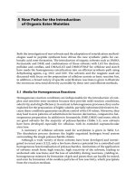
a. Step 1: Design fillet weld connecting each truss bar and gusset plate
The maximum normal load in a truss bar is N max (considering both tension and compression
load).
Based on [1] – chapter 2,
2, personally, the stages are
are:
The load acts to fillet weld is divided in to 2 component loads: N1 and N 2
With N1 = k × N and N 2 = (1- k)× N
election of electrode grade for fillet weld: N42 or N46, from that the value
From the sselect
election
( .f w ) min can be determined.
Select preliminary size of filet weld:
weld h f 1 andh f 2 which are satisfied requirements
about the allowable maximum and minimum sizes of filet weld.
Calculate required
required length for each fillet weld:
L w1
andL w 2
2(f w ) min h f 1 c
2(f w ) min h f 2 c
It is better if to reduce the sizes of gusset plate, required length for each fillet weld is as the
smallest value as possible (50 mm), and the corresponding size of fillet weld is adaptable.
Also, to increase the rat
ratee of welding process , the sizes of these fillet welds should be equal.
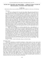
b. Step 2: Design preliminary shape of gusset plate
The shape of gusset plate depend on various factors including: section of truss bars, angles
between
between each bar with column and between each two truss bars, the required length of each
fillet weld which connecting
connecting truss bars and gusset plate, etc.
esigning
ing a good preliminary shape of gusset plate is shown as
My personal procedure for ddesign
esign
the following figure:
Eng. Vy Son Tung – Division of Steel and Timber Structure
8
NATIONAL UNIVERSITY OF CIVIL ENGINEERING
SINGLE
SINGLE-STOREY
STOREY STEEL INDUSTRIAL BUILDING,
FACULTY OF INDUSTRIAL & CIVIL ENGINEERING
INTRODUCTION
c. Design fillet weld connecting gusset plate and end plate
Determine
Determine load acts to fillet weld:
In this case, it is a resultant load of normal loads into the diagonal member and bottom
chord.
Eng. Vy Son Tung – Division of Steel and Timber Structure
9