Rolling bearing analysis
Bạn đang xem bản rút gọn của tài liệu. Xem và tải ngay bản đầy đủ của tài liệu tại đây (26.8 MB, 550 trang )
This book is printed on acid-free paper. @)
Copyright © 2001 by John Wiley & Sons, Inc. All rights resorvud.
Published simultaneously in Canada.
No part of this publication may be reproduced, stored in a retriuvnl My.tum ur transmitted in any
form or by any means, electronic, mechanical, photocopying, rl,corclinlC,IIcllnnlng or otherwise,
except as permitted under Sections 107 or 108 of the 1976 Unitod 8tlltUil Cupyright Act, without
either the prior written permission of the Publisher, or authorization through payment of the
appropriate per-copy fee to the Copyright Clearance Center, 222 Rosewood Drive, Danvers, MA
01923, (978) 750-8400, fax (978) 750-4744. Requests to the Publisher for permission should be
addressed to the Permissions Department, John Wiley & Sons, Inc., 605 Third Avenue, New York,
NY 10158-0012, (212) 850-6011, fax (212) 850-6008, E-Mail:
This publication is designed to provide accurate and authoritative information in regard to the
subject matter covered. It is sold with the understanding that the publisher is not engaged in
rendering professional services. If professional advice or other expert assistance is required, the
services of a competent professional person should be sought.
Library ofCongresB Cataloging-in-Publication
Data:
Harris, Tedric A.
Rolling bearing analysis / Tedric A. Harris. - 4th ed.
p. em.
Includes index.
ISBN 0-471-35457-0 (cloth: alk. paper)
1. Roller bearings. 2. Ball-bearings.
TJ1071.H35 2001
621.8'22-dc21
Printed in the United States of America.
10 9 8 7 6 5 4 3 2
PREFACE
1. ROLLING BEARING TYPES AND APPLICATIONS
Introduction to Rolling Bearings
Ball Bearings
Roller Bearings
Linear Motion Bearings
Bearings for Special Applications
Closure
2. ROLLING BEARING MACROGEOMETRY
00-038171
List of Symbols
General
Ball Bearings
Spherical Roller Bearings
Radial Cylindrical Roller Bearings
Tapered Roller Bearings
Closure
xiii
1
1
11
23
40
41
44
47
47
48
49
66
73
77
79
vi
CONTENTS
3. INTERFERENCE
FITTING AND CLEARANCE
List of Symbols
General
Industrial, National, and International Standards
Effect of Interference Fitting on Clearance
Press Force
Differential Expansion
Effect of Surface Finish
Closure
4. BEARING LOADS AND SPEEDS
List of Symbols
General
Concentrated Radial Loading
Concentrated Radial and Moment Loading
Shaft Speeds
Distributed Load Systems
Closure
5. BALL AND ROLLER LOADS
List of Symbols
General
Static Loading
Dynamic Loading
Roller Axial Loading in Radial Bearings
Closure
6. CONTACT STRESS AND DEFORMATION
List of Symbols
General
Theory of Elasticity
Surface Stresses and Deformations
Subsurface Stresses
Effect of Surface Shear Stress
Type of Contact
Roller End-Flange Contact Stress
Closure
81
81
83
84
86
123
123
125
130
133
133
134
135
143
150
153
153
155
155
157
157
161
177
181
183
183
185
185
189
204
215
218
225
228
7. DISTRIBUTION OF INTERNAL LOADING
IN STATICALLY LOADED BEARINGS
List of Symbols
231
?~1
CONTENTS
General
Load-Deflection Relationships
Bearings under Radial Load
Bearings under Thrust Load
Bearings under Combined Radial and Thrust Load
Ball Bearings under Combined Radial, Thrust, and
Moment Load
Misalignment of Radial Roller Bearings
Thrust Loading of Radial Cylindrical Roller Bearings
Radial, Thrust, and Moment Loading of Radial
Roller Bearings
Flexibly Supported Rolling Bearings
Closure
8. INTERNAL SPEEDS AND MOTIONS
List of Symbols
General
Simple Rolling Motion
Rolling and Sliding
Orbital, Pivotal, and Spinning Motions in Ball Bearings
Roller End-Flange Sliding in Roller Bearings
Closure
vii
233
234
235
245
256
266
272
280
289
291
302
307
307
308
309
313
317
330
335
9. DISTRIBUTION OF INTERNAL LOADING IN
HIGH SPEED BEARINGS
List of Symbols
General
High Speed Ball Bearings
High Speed Radial Cylindrical Roller Bearings
High Speed Tapered and Spherical Roller Bearings
Five Degrees of Freedom in Loading
Closure
10. BEARING DEFLECTION AND PRE LOADING
List of Symbols
General
Deflections of Bearings with Rigid Rings
Preloading
Limiting Ball Bearing Thrust Load
C,lmmrp
337
337
338
339
349
355
358
360
363
363
364
365
368
379
•..•
n ••
viii
CONTENTS
11. STATICALLY INDETERMINATE
SHAFT-BEARING
SYSTEMS
List of Symbols
General
Two-Bearing Systems
Three-Bearing Systems
Multiple-Bearing Systems
Closure
387
387
388
389
400
410
412
12. LUBRICANT FILMS IN ROLLING
ELEMENT-RACEWAY
List of Symbols
General
CONTACTS
Hydrodynamic Lubrication
Isothermal Elastohydrodynamic Lubrication
Very High Pressure Effects
Inlet Lubricant Frictional Heating Effects
Starvation of Lubricant
Surface Topography Effects
Grease Lubrication
Lubrication Regimes
Closure
13. FRICTION IN FLUID-LUBRICATED
ELEMENT-RACEWAY
List of Symbols
General
415
415
418
419
424
440
441
444
446
4151
4154
4156
ROLLING
CONTACTS
Microgeometry and Microcontacts
Asperity- and Fluid-Supported Load
Friction in the EHL Contact
Closure
14. FRICTION IN ROLLING BEARINGS
List of Symbols
General
Sources of Friction
Friction Forces and Moments in Rolling Element-Raceway
Contacts
Skidding and Cage Forces
Cage Motions and Forces
481
461
468
464
472
478
479
488
488
485
486
496
5115
529
CONTENTS
Roller Skewing
Bearing Friction Torque
Closure
15. ROLLING BEARING TEMPERATURES
List of Symbols
General
Heat Generation
Heat Transfer
Analysis of Heat Flow
High Temperature Considerations
Heat Transfer in a Rolling-Sliding Contact
Closure
16. BEARING STRUCTURAL MATERIALS
General
Rolling Bearing Steels
Steel Manufacture
Effects of Processing Methods on Steel Components
Heat Treatment of Steel
Rolling Contact Fatigue: Modes and Causes
Materials for Special Bearings
Cage Materials
Seal Materials
Surface Treatments for Bearing Components
Closure
17. LUBRICANTS AND LUBRICATION TECHNIQUES
List of Symbols
General
Types of Lubricants
Lubrication Methods
Liquid Lubricants
Grease Lubricants
Polymeric Lubricants
Solid Lubricants
Environmentally Acceptable Lubricants
Seals
Closure
ix
534
540
547
551
551
552
553
556
561
569
574
577
579
579
579
582
597
597
618
620
625
632
638
641
645
645
645
646
648
654
662
668
670
671
672
682
x
CONTENTS
18. FATIGUE LIFE: LUNDBERG-PALMGREN
THEORY AND RATING STANDARDS
List of Symbols
General
Fatigue Life Dispersion
Weibull Distribution
Dynamic Capacity and Life of a Rolling Contact
Fatigue Life of a Rolling Bearing
Effect of Steel Composition and Processing on Fatigue Life
Load Rating Standards
Closure
683
683
686
688
692
699
707
739
742
761
19. BEARING ENDURANCE TESTING AND ELEMENT
TESTING METHODS
List of Symbols
General
Theoretical Basis of Life Testing
Practical Testing Considerations
Test Samples
Test Rig Design Considerations
Element Testing
Rolling-Sliding Contact Friction Testing
Closure
20. STATISTICAL METHODS TO ANALYZE ENDURANCE
List of Symbols
General
The Two-Parameter Weibull Distribution
Estimation in Single Samples
Estimation in Sets of Weibull Data
Closure
21. PERMANENT
DEFORMATION
STATIC CAPACITY
List of Symbols
General
763
763
763
764
768
772
777
779
784
791
793
793
794
795
800
811
816
AND BEARING
Calculation of Permanent Deformation
Static Load Rating of Bearings
Static Equivalent Load
819
819
820
820
825
828
CONTENTS
x
Fracture of Bearing Components
Permissible Static Load
Closure
22. MATERIAL RESPONSE
TO ROLLING CONTACT
List of Symbols
General
Microstructures of Rolling Bearing Steels
Microstructural Alterations Due to Rolling Contact
Residual Stresses in Rolling Bearing Components
Effects of Bulk Stresses on Material Response to
Rolling Contact
Closure
23. APPLICATION
LOAD AND LIFE FACTORS
List of Symbols
General
Effect of Bearing Internal Load Distribution on Fatigue Life
Effect of Variable Loading on Fatigue Life
Fatigue Life of Oscillating Bearings
Reliability and Fatigue Life
Effect of Lubrication on Fatigue Life
Effect of Material and Material Processing on Fatigue Life
Effect of Contamination on Fatigue Life
Combining Fatigue Life Factors
Limitations of the Lundberg-Palmgren Theory
Ioannides- Harris Theory
The Stress-Life Factor
Closure
24. WEAR
List of Symbols
General
Structural Elements of a Lubricated Contact
Tribological Processes Associated with Wear
Phenomenological View of Wear
Interacting Tribological Processes and Failure Modes
Recommendations for Wear Protection
Closure
83J
83J
83~
83f
831
831
83(
834
84~
85~
854
86]
86]
86~
864
874
81£
88E
89C
894
89E
90~
904
90E
90~
93]
936
931
93E
937
939
949
953
955
958
xii
CONTENTS
25. VIBRATION, NOISE, AND CONDITION MONITORING
List of Symbols
General
Vibration and Noise-Sensitive Applications
The Role of Bearings in Machine Vibration
Nonroundness Effect and Its Measurement
Detection of Failing Bearings in Machines
Failure Detection-Condition Monitoring
Condition-Based Maintenance
Closure
26. ROTOR DYNAMICS AND CRITICAL SPEEDS
List of Symbols
General
Damped Forced Vibrations
Coupled Vibratory Motion (Rigid Shaft)
Multi-Degree-of-Freedom System (Flexible Shaft)
Bearing Stiffness
Characteristics of Bearing Stiffness
Rotor Dynamics Analysis
Closure
963
963
963
964
968
980
997
1003
1005
1010
1013
1013
1014
1015
1020
1024
1028
1033
1039
1042
27. INVESTIGATION
AND ANALYSIS OF BEARING
FAILURES
General
Preliminary Investigation
Disassembly of Bearings
Failure Mechanisms
Examination and Evaluation of Specific Conditions
Fractography
Closure
1043
1043
1043
1044
1044
1049
1063
1068
APPENDIX
1071
INDEX
1074
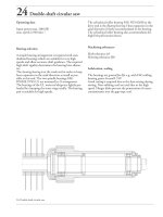
Ball and roller bearings, generically called rolling bearings, are commonly used machine elements. They are employed to permit rotary motion of, or about, shafts in simple commercial devices such as bicycles,
roller skates, and electric motors. They are also used in complex engineering mechanisms such as aircraft gas turbines, rolling mills, dental
drills, gyroscopes, and power transmissions. Until approximately 1940,
the design and application of these bearings could be considered more
art than science. Little was understood about the physical phenomena
that occur during their operation. Since 1945, a date which marks the
end of World War II and the beginning of the atomic age, scientific progress has occurred at an exponential pace. Since 1958, the date which
marks the commencement of manned space travel, continually increasing demands are being made of engineering equipment. To ascertain the
effectiveness of rolling bearings in modern engineering applications, it is
necessary to obtain a firm understanding of how these bearings perform
under varied and often extremely demanding conditions of operation.
Most information and data pertaining to the performance of rolling
bearings are presented in manufacturers' catalogs. These data are almost entirely empirical in nature, being either obtained from the testing
of products by the larger bearing manufacturing companies or, more
xiii
xiv
PREFACE
likely for smaller manufacturing companies, based on information contained in the American National Standards Institute (ANSI) or International Organization for Standards (ISO) publications or similar
publications. These data pertain only to applications involving slow
speed, simple loading, and nominal operating temperatures. If an engineer wishes to evaluate the performance of bearing applications operating beyond these bounds, it is necessary to return to the basics of
rolling and sliding motions over the concentrated contacts that occur in
rolling bearings.
One of the first books written on this subject was Ball and Roller
Bearing Engineering by Arvid Palmgren, Technical Director of ABSKF
for many years. It explained, more completely than had been done previously, the concept of rolling bearing fatigue life. Palmgren, together
with Gustav Lundberg, Professor of Mechanical Engineering at Chalmers Institute of Technology in Goteborg, Sweden, was the originator of
the theory and formulas on which the current ANSI and ISO standards
for the calculation of rolling bearing fatigue life are based. Also, A.
Burton Jones's book in two volumes, Analysis of Stresses and Deflections,
gave a good explanation of the static loading of ball bearings. Jones, who
worked in various technical capacities for New Departure Ball Bearings
Division of General Motors Corporation, Marlin-Rockwell Corporation,
and Fafnir Ball Bearing company, and also as a consulting engineer, pioneered the use of digital computers to analyze the performance of ball
and roller bearing shaft-bearing-housing
systems. The remainder of
other early and subsequent texts on rolling bearings were, and are,
largely empirical in their approaches to applications analysis. Particularly since 1960, much research has been conducted into rolling bearings
and rolling contact phenomena. The use of modern laboratory equipment
such as scanning and transmission electron microscopes, x-ray diffraction devices, and high speed digital computers has shed much light on
the mechanical, hydrodynamic, metallurgical, and chemical phenomena
involved in rolling bearing operation. Many significant technical papers
have been published by various engineering societies-for example, the
American Society of Mechanical Engineers, the Institution of Mechanical
Engineers, the Society of Tribologists and Lubrication Engineers, and
the Japan Society of Mechanical Engineers-analyzing the performance
of rolling bearings in exceptional applications involving high speed,
heavy load, and extraordinary internal design and materials. Since 1960,
substantial attention has been given to the mechanisms of rolling bearing lubrication and the rheology of lubricants. Notwithstanding the existence of the aforementioned literature, there remains a need for a
reference that presents a unified, up-to-date approach to the analysis of
rolling bearing performance. That is my intention in presenting this
book.
To accomplish this goal, I have attempted to review the most significant technical papers and texts covering the performance of rolling bear-
PREFACE
xv
ings, their constituent materials, and lubrication. The concepts and
mathematical presentations contained in the reviewed technical literature have been condensed and simplified in this book for rapidity and
ease of understanding. It should not be construed, however, that this
book supplies a complete bibliography on rolling bearings. Only those
data that I found most useful in practical analysis have been referenced.
Several of the references cited are my own works, since in some cases
these are the original or are among the most significant available on the
particular subject.
The format of Rolling Bearing Analysis is aimed at developing for the
reader a basic understanding of rolling bearing operation. Thus, the initial chapters discuss the simplest concepts of rolling bearings, such as
basic bearing types, geometries, applied loading, loading of single balls
and rollers, and contact stresses and deformations. Then, the complex
analysis of load distribution among the rolling elements, component
speeds, and velocities, elastohydrodynamic lubrication, friction, temperatures, statistics of bearing endurance, and fatigue life are considered.
Several topics depend almost entirely on the preceding discussions. As
nearly as possible, an attempt has been made to maintain continuity of
presentation. To amplify the discussion, numerical examples are presented in most chapters. For instance, numerical examples deal with a
209 radial ball bearing, a 209 cylindrical roller bearing, a 218 angularcontact ball bearing, and a 22317 spherical roller bearing in many chapters. Analytical data for each bearing are accumulated as the reader
progresses through the book. The examples are carried out in metric or
standard international (SI) system units (millimeters, Newtons, seconds,
°C, and so on); however, the results are also given parenthetically in
English system units. In the Appendix, the numerical constants for equations presented in SI or metric system units are provided in English
system units as well.
The material covered herein spans many scientific disciplines, such as
geometry, elasticity, statics, dynamics, hydrodynamics, statistics, and
heat transfer. Thus, many mathemathical symbols have been employed.
In some cases, the same symbol has been chosen to represent different
parameters in different chapters. To help avoid confusion, a list of symbols is presented at the beginning of most chapters. In the interest of
clarity, however, certain symbols have been retained for singular usage.
For example, D is always ball or roller diameter, dm is always bearing
pitch diameter, and a is always contact angle.
Because of the several scientific disciplines that this book spans, the
treatment of each topic may vary somewhat in scope and manner. Where
feasible, analytical solutions to problems have been presented. On the
other hand, empirical approaches to problems have been used where it
seemed more practical. The wedding of analytical and empirical techniques is particularly evident in the chapters covering lubrication, friction, and fatigue life.
xvii
PREFACE
particularly in the area of rolling contact fatigue. This has afforded me
the opportunity to continue development of the Ioannides-Harris fatigue
life theory; the results of this development are presented in Chapter 23.
This material represents not only the results of my research, but also
the substantial collaborative efforts of the ASME Tribology Division
Technical Committee on Life Ratings for Modern Rolling Bearings. In
addition to myself, contributing significantly to the results of this committee are the following members: Roger Barnsby, Pratt and Whitney,
United Technologies Corporation; Dr. Stathis Ioannides, SKF Engineering and Research Centre, the Netherlands; Dr. Thomas Losche, FAG
Bearings, Germany; Dr. Kikua Maeda, NTN, Japan; Dr. Yasuo Murakami, NSK, Japan; Harvey Nixon and Michael Hoeprich, the Timken
Company; and Dr. Martin Webster, Mobil Oil Company.
As stated previously, the material presented herein exists substantially in other publications, The purpose of this text is to concentrate
that knowledge in one place for the benefit of both the student and the
rolling bearing user who need or want a broader understanding of the
technical field and/or product. The references provided at the end of each
chapter enable the curious reader to go into further detail.
Because of my longtime association with the SKF company, as with
the previous editions of this text, several of the illustrations in this 4th
edition have previously appeared in SKF publications; for such illustrations, appropriate references are identified. In this edition, however, I
have included photographs and illustrations from other rolling bearing
manufacturers as well. I would like to express my appreciation to the
following companies for contributing photographic material: FAG OEM
und Handel AG, Schweinfurt, Germany; NSK Corporation; NTN Bearing
Corporation of America; the Timken Company, Canton, Ohio; Torrington
Bearings Division, Ingersoll Rand Corporation, Torrington, Connecticut.
The contributor of each such illustration is identified.
TEDRIC
Professor of Mechanical Engineering
The Pennsylvania State University
University Park, Pennsylvania
A.
HARRIS
INTRODUCTION
TO ROLLING BEARINGS
After the invention of the wheel, it was learned that less effort was required to move an object on rollers than to slide the object over the same
surface. Even after lubrication was discovered to reduce the work required in sliding, rolling motion still required less work when it could be
used. For example, archeological evidence shows that the Egyptians, ca.
2400 BC, employed lubrication, most likely water, to reduce the manpower required to drag sledges carrying huge stones and statues. The
Assyrians, ca. 1100 BC, however, employed rollers under the sledges to
achieve a similar result with less manpower. It was therefore inevitable
that bearings using rolling motion would be developed for use in complex
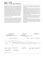
machinery and mechanisms. Figure 1.1 depicts, in a simplistic manner,
the evolution of rolling bearings. Dowson [1.1] provides a comprehensive
presentation on the history of bearings and lubrication in general; his
coverage on ball and roller bearings is extensive. Although the concept
of rolling motion was known and used for thousands of years, and simple
forms of rolling bearings were in use ca. 50 AD during the Roman civilization, the general use of rolling bearings did not occur until the industrial revolution. Reti [1.2], however, shows that Leonardo da Vinci
1
4
ROLLING BEARING TYPES AND APPLICATIONS
rior rolling bearing steels and constant improvement in manufacturing,
providing extremely accurate geometry, long-lived rolling bearing assemblies. Initially this development was triggered by the bearing requirements for high speed aircraft gas turbines; however, competition between
ball and roller bearing manufacturers for worldwide markets increased
substantially during the 1970s, and this has served to provide consumers
with low-cost, standard design bearings of outstanding endurance. The
term rolling bearings includes all forms of bearings that utilize the rolling action of balls or rollers to permit minimum friction, constrained
motion of one body relative to another. Most rolling bearings are employed to permit rotation of a shaft relative to some fixed structure. Some
rolling bearings, however, permit translation, that is, relative linear motion, of a fixture in the direction provided by a stationary shaft, and a
few rolling bearing designs permit a combination of relative linear and
rotary motion between two bodies.
This book is concerned primarily with the standardized forms of ball
and roller bearings that permit rotary motion between two machine elements. These bearings will always include a complement of balls or
rollers that maintain the shaft and a usually stationary supporting structure, frequently called a housing, in a radially or axially spaced-apart
relationship. Usually, a bearing may be obtained as a unit, which includes two steel rings each of which has a hardened raceway on which
hardened balls or rollers roll. The balls or rollers, also called rolling elements, are usually held in an angularly spaced relationship by a cage,
whose function was anticipated by Leonardo. The cage may also be called
a separator or retainer.
Balls, rollers, and rings of good quality, rolling bearings are normally
manufactured from steels that have the capability of being hardened to
a high degree, at least on the surface. In universal use by the ball bearing
industry is AISI 52100, a steel moderately rich in chromium and easily
hardened throughout (through-hardened) the mass of most bearing components to 61-65 Rockwell C scale hardness. This steel is also used in
roller bearings by some manufacturers. Miniature ball bearing manufacturers, whose bearings are used in sensitive instruments such as
gyroscopes, prefer to fabricate components from stainless steels such as
AISI 440C. Roller bearing manufacturers frequently prefer to fabricate
rings and rollers from case-hardening steels such as AISI 3310, 4118,
4620, 8620, and 9310. For some specialized applications, such as automotive wheel hub bearings, the rolling components are manufactured
from induction-hardening steels. In all cases, at least the surfaces of the
rolling components are extremely hard. In some high speed applications,
to minimize inertial loading of the balls or rollers, these components are
fabricated from lightweight, high compressive strength ceramic materials such as silicon nitride. Also, these ceramic rolling elements tend to
INTRODUCTION
TO ROLLING BEARINGS
5
endure longer than steel at ultrahigh temperatures and in applications
with dry film or minimal fluid lubrication.
Cage materials, as compared to materials for balls, rollers, and rings,
are generally required to be relatively soft. They must also possess good
strength-to-weight ratio; therefore, materials as widely diverse in physical properties as mild steel, brass, bronze, aluminum, polyamide (nylon),
polytetrafluoroethylene (teflon or PTFE), fiberglass, and plastics filled
with carbon fibers find use as cage material.
In this modern age of deep-space exploration and cyberspace, many
different kinds of bearings have come into use, such as gas film bearings,
foil bearings, magnetic bearings, and externally pressurized (hydrostatic)
bearings. Each of these bearing types excels in some specialized field of
application. For example, hydrostatic bearings are excellent for applications in which size is no problem, an ample supply of pressurized fluid
is available, and extreme rigidity under heavy loading is required. Selfacting gas bearings may be used for applications in which loads are light,
speeds are high, a gaseous atmosphere exists, and friction must be minimal. Rolling bearings, however, are not quite so limited in scope. Consequently, miniature ball bearings such as shown in Fig. 1.3 are found
in precision applications such as inertial guidance gyroscopes and high
speed dental drills, large roller bearings, such as shown in Fig. 1.4, are
utilized in metal rolling mill applications, and even larger slewing bearings, as illustrated in Fig. 1.5, were used in tunneling machines for the
"Chunnel" (English Channel tunneling) project.
Moreover, rolling bearings find use in diverse precision machinery operations; for example, the high load, high temperature, dusty environment of steel-making (Fig. 1.6), the dirty environments of earthmoving
and farming (Figs. 1.7 and 1.8), the life-critical applications in aircraft
power transmissions (Fig. 1.9), and the extreme low-high temperature
and vacuum environments of deep space (Fig. 1.10). They perform well
in all of these applications. Specifically, rolling bearings have the following advantages compared to other bearing types:
• They operate with much less friction torque than hydrodynamic
bearings and therefore considerably less power loss and friction heat
generation .
· Starting friction torque is only slightly greater than moving friction
torque.
• Bearing deflection is less sensitive to load fluctuation than in hydrodynamic bearings.
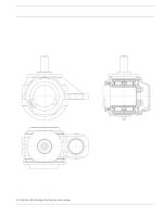
(b)
FIGURE 1.5. Large slewing bearing used in an English Channel tunneling machine.
Photograph; (b) schematic drawing of the assembly (courtesy of SKF).
(a)
. They require only small quantities of lubricant for satisfactory operation and have the potential for operation with a self-contained, life-long
supply of lubricant.
. They occupy shorter axial length than conventional hydrodynamic
bearings.
• Combinations of radial and thrust loads can be supported simultaneously.
• Individual designs yield excellent performance over a wide load-speed
range.
• Satisfactory performance is relatively insensitive to fluctuations in
load, speed, and operating temperature.
Notwithstanding the foregoing advantages, rolling bearings have been
considered to have a single disadvantage compared to hydrodynamic
bearings. Tallian [1.3] defined three eras of modern rolling bearing development: an "empirical" era extending through the 1920s, a "classical"
era lasting through the 1950s, and the "modern" era occurring thereafter.
Through the empirical, classical, and even into the modern era, it was
said that even if rolling bearings are properly lubricated, properly
mounted, protected from dirt and moisture, and otherwise properly operated, they will eventually fail because of fatigue of the surfaces in rolling contact. Historically, as shown in Fig. 1.11, rolling bearings have
been considered to have a life distribution statistically similar to that of
light bulbs and human beings.
Research in the 1960s [1.4] demonstrated that rolling bearings exhibit
a minimum fatigue life; that is, "crib deaths" due to rolling contact
fatigue do not occur when the foregoing criteria for good operation are
achieved. Moreover, modern manufacturing techniques enable producGionof bearings with extremely accurate component internal and exter-
nal geometries and extremely smooth rolling contact surfaces, modern
steel-making processes can provide rolling bearing steels of outstanding
homogeneity with few impurities, and modern sealing and lubricant filtration methods act to minimize the incursion of harmful contaminants
into the rolling contact zones. These methods, which are now being used
in combination in many applications, can virtually eliminate the occurrence of rolling contact fatigue, even in some applications involving very
heavy applied loading. In many lightly loaded applications, for example,
most electric motors, fatigue life need not be a major design consideration.
There are many different kinds of rolling bearings, and before embarking on a discussion of the theory and analysis of their operation, it
is necessary to become somewhat familiar with each type. In the succeeding pages a description is given for each of the most popular ball
and roller bearings in current use.
BALL BEARINGS
Radial Ball Bearings
Single-Row Deep-Groove Conrad Assembly Ball Bearing.
This ball bearing is shown in Fig. 1.12, and it is the most popular rolling bearing. The
inner and outer raceway grooves have curvature radii between 51.5 and
53% of the ball diameter for most commercial bearings.
To assemble these bearings, the balls are inserted between the inner
and outer rings as shown by Figs. 1.13 and 1.14. The assembly angle 1>
is given as follows:
1>
=
2(Z - 1) D/dm
(1.1)
in which Z is the number of balls, D is ball diameter, and d m is pitch
diameter. The inner ring is then snapped to a position concentric with
the outer ring, the balls are separated uniformly, and a riveted cage as
shown in Fig. 1.14 or a plastic cage as illustrated by Fig. 16.25a is inserted to maintain the separation. Because of the high osculation and an
appropriate ball diameter and ball complement to substantially fill the
bearing pitch circle, the deep-groove ball bearing has comparatively high
load-carrying capacity when accurately manufactured from good-quality
steel and operated in accordance with good lubrication and contaminantexclusion practices. Although it is designed to carry radial load, it performs well under combined radial and thrust load and under thrust
alone. With proper caged design, deep-groove ball bearings can with-
14
ROLLING BEARING TYPES AND APPLICATIONS
stand misaligning loads (moment loads) of small magnitude. By making
the bearing outside surface a portion of a sphere as illustrated in Fig.
1.15, however, the bearing can be made externally self-aligning and,
thus, incapable of supporting a moment load.
The deep-groove ball bearing can be readily adapted with seals as
shown in Fig. 1.16 or shields as shown by Fig. 1.17 or both as illustrated
by Fig. 1.18. These components function to keep lubricant in the bearing
and exclude contaminants. Seals and shields come in many different configurations to serve general or selective applications; those shown in
Figs. 1.16-1.18 should be taken only as examples. In Chapter 17, seals
are discussed in greater detail.
Deep-groove ball bearings perform well at high speeds provided adequate lubrication and cooling are available. Speed limits shown in manufacturers' catalogs generally pertain to bearing operation without the
benefit of external cooling capability or special cooling techniques.
Conrad assembly bearings can be obtained in different dimension series according to ANSI and ISO* standards. Figure 1.19 shows the relative dimensions of various ball bearing series.
Single-Row Deep-Groove Filling-Slot Assembly Ball Bearings. This
bearing as illustrated in Fig. 1.20 has a slot machined in the side wall
of each of the inner and outer ring grooves to permit the assembly of
more balls than the Conrad type does, and thus it has more radial loadcarrying capacity. Because the slot disrupts the groove continuity, the
bearing is not recommended for thrust load applications. Otherwise, the
bearing has characteristics similar to those of the Conrad type.
Double-Row Deep-Groove Ball Bearings. This ball bearing as shown in
Fig. 1.21 has greater radial load-carrying capacity than the single-row
types. Proper load sharing between the rows is a function of the geometrical accuracy of the grooves. Otherwise, these bearings behave similarly to single-row ball bearings.
Instrument Ball Bearings. In metric design, the standardized form of
these bearings ranges in size from 1.5-mm CO.05906-in.)bore and 4-mm
CO.
15748-in.) o.d. to 9-mm (0.35433-in.) bore and 26-mm (1.02362-in.) o.d.
See reference [1.5].As detailed in reference [1.6], standardized form, inch
design instrument ball bearings range from 0.635-mm CO.0250-in.)bore
and 2.54-mm (O.IOO-in.)o.d. to 19.050-mm (O.7500-in.) bore and 41.275mm C1.6250-in.)o.d. Additionally, instrument ball bearings have extra
thin series that range up to 47.625-mm C1.8750-in.)o.d. and thin series
that range up to lOO-mm C3.93701-in.)o.d. Those bearings having less
than 9-mm CO.3543-in.)o.d. are classified as miniature ball bearings according to [1.6]; such bearings can use balls as small as O.6350-mm
CO.0250-in.)diameter. Figure 1.3 illustrates this type of bearing. They
are fabricated according to more stringent manufacturing standards,
such as for cleanliness, than are any of the bearings previously described.
This is because minute particles of foreign matter can significantly increase the friction torque and negatively affect the smooth operation of
the bearings. For this reason, they are assembled in a white room as
illustrated in Fig. 1.22.
Groove radii of instrument ball bearings are usually not smaller than
57% of the ball diameter. The bearings are usually fabricated from stainless steels since corrosion particles will seriously deteriorate bearing performance.
Angular-Contact Ball Bearings
Single-Row Angular-Contact Ball Bearings. Angular-contact ball bearings as shown in Fig. 1.23 are designed to support combined radial and
thrust loads or heavy thrust loads depending on the contact angle magnitude. The bearings having large contact angles can support heavier
thrust loads. Figure 1.24 shows bearings having small and large contact
angles. The bearings generally have groove curvature radii in the range
of 52-53% of the ball diameter. The contact angle does not usually exceed
40°. The bearings are usually mounted in pairs with the free endplay
removed as shown in Fig. 1.25. These sets may be preloaded against each
other to stiffen the assembly in the axial direction. The bearings may
also be mounted in tandem as illustrated in Fig. 1.26 to achieve greater
thrust-carrying capacity.
Double-Row Angular-Contact Ball Bearings. These bearings as depicted
in Fig. 1.27 can carry thrust load in either direction or a combination of
radial and thrust load. Bearings of the rigid type are able to withstand
moment loading effectively. Essentially, the bearings perform similarly
to duplex pairs of single-row angular-contact ball bearings.
Self Aligning Double-Row Ball Bearings. As illustrated in Fig. 1.28, the
outer raceway of this bearing is a portion of a sphere. Thus, the bearings
are internally self-aligning and cannot support a moment load. Because
the balls do not conform well to the outer raceway (it is not grooved), the
outer raceway has reduced load-carrying capacity. This is compensated
somewhat by use of a very large ball complement that minimizes the
load carried by each ball. The bearings are particularly useful in applications in which it is difficult to obtain exact parallelism between the
shaft and housing bores. Figure 1.29 shows this bearing with a tapered
sleeve and locknut adapter. With this arrangement the bearing does not
require a locating shoulder on the shaft.
Split Inner Ring Ball Bearings. These bearings are illustrated in Fig.
1.30. As can be seen, the inner ring consists of two axial halves such
that a heavy thrust load can be supported in either direction. They may
also support, simultaneously, moderate radial loading. The bearings have
found extensive use in supporting the thrust loads acting on high speed,
gas turbine engine mainshafts. Figure 1.31 shows the compressor and
turbine shaft ball bearing locations in a high-performance aircraft gas
turbine engine. Obviously, both the inner and outer rings must be locked
up on both axial sides to support a reversing thrust load. It is possible
with accurate flush grinding at the factory to utilize these bearings in
tandem as shown in Fig. 1.32 to share a thrust load in a given direction.
Thrust Ball Bearings
The thrust ball bearing illustrated in Fig. 1.33 has a 90° contact angle;
however, ball bearings whose contact angles exceed 45° are also classified
as thrust bearings. As for radial ball bearings, thrust ball bearings are
suitable for operation at high speeds. To achieve a degree of externally
aligning ability, thrust ball bearings are sometimes mounted on spherical
seats. This arrangement is demonstrated by Fig. 1.34. A thrust ball bearing whose contact angle is 90° cannot support any radial load.
ROLLER BEARINGS
General
Roller bearings are usually used for applications requiring exceptionally
large load-supporting capability, which cannot be feasibly obtained using
a ball bearing assembly. Roller bearings are usually much stiffer structures (less deflection per unit loading) and provide greater fatigue endurance than do ball bearings of a comparable size. In general, they also
cost more to manufacture, and hence purchase, than comparable ball
bearing assemblies. They usually require greater care in mounting than
do ball bearing assemblies. Accuracy of alignment of shafts and housings
can be a problem in all but self-aligning roller bearings.
Radial Roller Bearings
Cylindrical Roller Bearings. Cylindrical roller bearings as illustrated
in Fig. 1.35 have exceptionally low friction torque characteristics that
make them suitable for high speed operation. They also have high radialload-carrying capacity. The usual cylindrical roller bearing is free to float
axially. It has two roller-guiding flanges on one ring and none on the
other, as shown in Fig. 1.36. By equipping the bearing with a guide flange
on the opposing ring (illustrated by Fig. 1.37), the bearing can be made
to support some thrust load.
To prevent high stresses at the edges of the rollers the rollers are
usually crowned as shown in Fig. 1.38. This crowning of rollers also gives
the bearing protection against the effects of slight misalignment. The
crown is ideally designed for only one condition ofloading. Crowned raceways may be used in lieu of crowned rollers.
To achieve greater radial-load-carrying capacity, cylindrical roller
bearings are frequently constructed of two or more rows of rollers rather
than of longer rollers. This is done to reduce the tendency of the rollers
to skew. Figure 1.39 shows a small double-row cylindrical roller bearing
designed for use in precision applications. Figure 1.40 illustrates a large
multirow cylindrical roller bearing for a steel rolling mill application.
Needle Roller Bearings. A needle roller bearing is a cylindrical roller
bearing having rollers of considerably greater length than diameter. This
bearing is illustrated in Fig. 1.41. Because of the geometry of the rollers,
they cannot be manufactured as accurately as other cylindrical rollers,
nor can they be guided as well. Consequently, needle roller bearings have
relatively greater friction than other cylindrical roller bearings.
Needle roller bearings are designed to fit in applications in which radial space is at a premium. Sometimes to conserve space the needles
bear directly on a hardened shaft. They are useful for applications in
which oscillatory motion occurs or in which continuous rotation occurs
but loading is light and intermittent. The bearings may be assembled
without a cage, as shown in Fig. 1.42. In this full-complement-type bearing, the rollers are frequently retained by turned-under flanges that are
integral with the outer shell. The raceways are frequently hardened but
not ground.
Tapered Roller Bearings
The single-row tapered roller bearing shown in Fig. 1.43 has the ability
to carry combinations of large radial and thrust loads or to carry thrust
load only. Because of the difference between the inner and outer raceway
contact angles, there is a force component that drives the tapered rollers
the outer ring the cup. Depending on the magnitude of the thrust load
to be supported, the bearing may have a small or steep contact angle, as
shown in Fig. 1.44. Since tapered roller bearing rings are separable, the
bearings are mounted in pairs as indicated in Fig. 1.45, and one bearing
is adjusted against the other. To achieve greater radial load-carrying capacity and eliminate problems of axial adjustment due to distance between bearings, tapered roller bearings may be combined as shown in
Fig. 1.46 into two-row bearings. Fig. 1.47 shows a typical double-row
tapered roller bearing assembly for a railroad car wheel application.
Double-row bearings may also be combined into four-row or quad bearings for exceptionally heavy radial load applications such as rolling mills.
Figure 1.48 shows a quad bearing having integral seals.
As with cylindrical roller bearings, tapered rollers or raceways are
usually crowned to relieve heavy stresses on the axial extremities of the
rolling contact members.
By equipping the bearing with specially contoured flanges, a special
cage, and lubrication holes as shown by Fig. 1.49, a tapered roller bearing can be designed to operate satisfactorily under high load-high speed
conditions. In this case, the cage is guided by lands on both the cone rib
and the cup, and oil is delivered directly by centrifugal flow to the roller
end-flange contacts and cage rail-cone land contact.
Spherical Roller Bearings
Most spherical roller bearings have an outer raceway that is a portion
of a sphere; hence, the bearings, as illustrated by Fig. 1.50, are internally
self-aligning. Each roller has a curved generatrix in the direction transverse to rotation that conforms relatively closely to the inner and outer
raceways. This gives the bearing high load-carrying capacity. Various executions of double-row, spherical roller bearings are shown in Fig. 1.51.
Fig. 1.5Ia shows a bearing with asymmetrical rollers. This bearing,
similar to tapered roller bearings, has force components that drive the
rollers against the fixed central guide flange. Bearings such as illustrated
in Fig. 1.5Ib and 1.5Ic have symmetrical (barrel- or hourglass-shape)
rollers, and these force components tend to be absent except under high
speed operation. Double-row bearings having barrel-shape, symmetrical
rollers frequently use an axially floating central flange as illustrated by
Fig. 1.5Id. This eliminates undercuts in the inner raceways and permits
use of longer rollers, thus increasing the load-carrying capacity of the
bearing. Roller guiding in such bearings tends to be accomplished by