NX 10 mechatronics concept design
Bạn đang xem bản rút gọn của tài liệu. Xem và tải ngay bản đầy đủ của tài liệu tại đây (1.34 MB, 122 trang )
Mechatronics Concept Designer
What is it?
Mechatronics Concept Designer is an application that you use to simulate the complex
motion of mechanical systems interactively. It is designed to support the early machine
design phase that provides the basic machine concept including the mechanical, electrical,
fluid, and software aspects. It is a solution that transforms the machine creation process into
an efficient mechatronics design approach.
This application is built on the following principles:
Functional machine design
One of the main instruments in this is the functional model, which forms the foundation to
provide an interdisciplinary view of the mechatronics system machine. It lets you lay the
foundation for collaboration in detailed design by supporting the early design phase with a
functional design approach.
The functional model provides the link between the data management of the different
disciplines and the requirements. This enables the traceability of the customer demand data
down to the design departments. Further, the functional model provides a supporting
structure to come up with initial design concepts and has the features to perform an
evaluation of design alternatives.
Early system validation
Mechatronics Concept Designer introduces a verification technology that is built on a new
simulation engine. It helps validate concept designs at a very early stage of the
development process.
Multidisciplinary support
Mechatronics Concept Designer facilitates interdisciplinary concept design up front. The
following disciplines can jointly work on a project:
Mechanical engineer creates the design based on 3D shapes and kinematics.
Electrical engineer help select and position sensors and actuators.
Automation programmer designs the basic logical behavior of the machine. He
starts with time based behavior and then defines the event based control.
Modularity and reuse
Mechatronics Concept Designer provides the ability to capture knowledge in components
and store them in a library to enable the reuse of this knowledge in other projects. Since the
library components are based on already proven concepts, it improves the design quality
and speeds up development.
Mechatronics Concept Designer supports the definition of functional units such as those in
the VDW Standard Funktionsbeschreibung.
Where do I find it?
Application
Mechatronics Concept Designer
Mechatronics Concept Design workflow
The following represents a typical machine design workflow using Mechatronics Concept
Designer:
1. Define and manage design requirements.
o Gather and structure requirements.
o Add derived requirements.
o Link requirements to each other.
o Add more details to requirements using embedded tools like Microsoft
Word.
2. Create a functional model.
o Define basic functions of the system.
o Create a hierarchy based on a functional decomposition.
o Create and maintain alternatives for the functional design.
o Reuse functional units.
3. Create a logical model.
o Define the basic logical model of the system.
o Create a hierarchy based on the logical decomposition of the system.
4. Create tracelinks between the functional model and the logical model.
5. Define the mechanical concept.
o Define a rough 3D outline of the basic solution concept.
o Assign mechanical implementation objects to functional and logical tree.
o Add kinematics and dynamics.
6. Add basic physics and signals.
o Add basic physics and speed constraint and position constraint actuators.
o Add signal adaptors.
o Assign signal adaptor object to function and logical tree.
7. Define time based operations.
o Define how the actuators are controlled by operations.
o Arrange the sequence of operation with a time based notion.
o Assign operations to the corresponding functions in the function tree.
o Assign operations to the corresponding logics in the logical tree.
8. Add sensors.
o Add sensors that are triggered by collisions of system elements with sensor
objects, or sensors that are defined by a signal adapter.
9. Define event based operations.
o Define operations that are triggered by events that are generated by sensors
or other objects in the mechatronics systems, such as the position of an
actuator.
o Assign operations to the corresponding functions in the function tree.
10. Replace concept model with detailed model and transfer physics objects from the
rough geometries to the detailed ones.
11. Align sensors and actuators with ECAD.
12. Export sequence of operation in PLCOpen XML format to a PLC engineering tool
like STEP 7.
13. Test PLC program via OPC connection.
Identify mechatronics tool bars and navigators
You will use multiple tool bars, navigators, groups and commands in this course. Use this
topic to identify them properly and navigate through course instructions.
Main tool bar
The main tool bar refers to the tabs along the top of the NX window. Tabs include:
File
Home
Modeling
Assemblies
Curve
Analysis
View
Render
In this course, you will be directed to main tool bar functions with the following direction:
Choose File→All Applications→Machine Tool Builder.
Mechatronics tool bar
The Mechatronics tool bar is used to divide commands into groups based on their function.
Mechatronics groups include:
Systems Engineering -- Use this group to apply requirements, functions, logical
models, and dependencies.
Mechanical Concept -- Use this group to add or change model features.
Simulate -- Use this group to start and control simulations in mechatronics.
Mechanical -- Use this group to apply physics features to models.
Electrical -- Use this group to apply electrical features that are active during
simulations.
Automation -- Use this group to control kinematics and physical properties during
simulations.
Design Collaboration -- Use this group to interact with external programs by
importing and exporting data.
In this course, you will be directed through groups with the following direction:
Choose Home tab→Design Collaboration group→Replace Component
.
Resource bar
The Resource bar is the set of tabs located along the edge of the NX window. The tabs
displayed on the bar vary depending on your specific configuration and active application.
The resource bar is divided into four main categories:
1. Navigators
2. HD3D Tools
3. Integrated Browser Window (Windows only)
4. Palettes
Tabs commonly used in mechatronics include:
System Navigator
-- Use the System Navigator tab to view the requirements,
functional and logical models of a product. You can use the System Navigator to
attach dependent objects that help navigate across the requirements, functional,
logical models and the physical representations such as mechanical components,
electrical devices, operations or physics objects. Expanded functionality is available
when using NX in Teamcenter Integration mode.
Physics Navigator
-- Use the Physics Navigator tab to display the physical and
logical properties of mechanical elements.
Runtime Expression
-- Use the Runtime Expression tab to view expressions
that you created to apply equations, ratios and relationships between physics
properties.
Assembly Navigator
-- Use the Assembly Navigator tab to view components
used in the assembly and access assemblies commands.
Sequence Editor
-- You can create time based and event based operations.
After you create operations, use the Sequence Editor to view and create a sequence
of operations, similar to sequential function logic.
On the Resource Bar, choose Sequence Navigator
.
Activity: Run a simulation and monitor values
Estimated time to complete: 5-10 minutes
In this activity, you will use simulations to apply physics properties and motion to
mechatronics models. You can monitor motion and values that are introduced using
actuators, mechatronics signals, and external signals. You will use runtime simulation and
runtime inspector to run simulations and monitor values. You will apply basic simulation
commands including:
Play
Pause
Stop
Restart
Run a simulation
You will use simulation commands to simulate a robotic cell in Mechatronics Concept
Designer.
1. Open mcd01_training_plant_e.
2. Choose File tab→All Applications→Mechatronics Concept Designer.
3. Choose Home tab→Simulate group→Play
.
When the simulation is active, physics and motion characteristics that have been
assigned become active. If the simulation is active, many Mechatronics Concept
Designer commands are unavailable.
4. Choose Home tab→Simulate group→Stop
.
Notice that when the simulation is stopped the geometry returns to the positioning
established in the model.
5. Play the simulation and while it is running, in the Simulate group, select Restart
.
The simulation returns to the positioning established in the model and immediately
begins moving again.
6. In the Simulate group, select Pause
.
If the simulation is paused, it is still considered to be running. Stop the simulation to
access all of the mechatronics commands.
7. Stop the simulation.
Monitor simulation values
Use the runtime inspector to monitor the values of physics objects.
1. Choose Home tab→Simulate group→Play
.
2. In the Simulate group, click Runtime Inspector.
3. In the Physics Navigator, in the Sensors and Actuators group, select arm motor.
The runtime inspector dialog box lists the characteristics of the selected object.
4. Verify the motor speed in the Runtime Inspector dialog box.
5. To pause the simulation and view the current values, in the Simulate group, click
Pause
6. Click Stop
.
.
Set simulation preferences
Use the runtime inspector to monitor the values of physics objects.
1. Choose File tab→All Preferences→Mechatronics Concept Designer.
2. Click the Physics Engine tab.
3. In the Runtime Parameters group, set the following:
o Collision Precision = 3
o Step Time = 0.1
4. Click OK.
5. Run the simulation to see the results and then stop the simulation.
Adjusting the preference values for the simulation can have either positive or
negative results. In this activity, the adjustments are detrimental. Use these
parameters to optimize a simulation that does not run smoothly. The step time is a
refresh rate for updating the model. The collision precision value adjusts the
accuracy of the collision shapes.
6. Return the values to the default values:
o Collision Precision = 0.0039 inches
o Step Time = 0.001
7. Run the simulation to see the results and then stop the simulation.
8. Close the file without saving.
You completed the activity.
Use joints to direct motion
Use joints to create motion restrictions between pieces of geometry. You can create joints
with force and torque limitations. You can use the following joints:
Hinge joint
Use the Hinge Joint command to create a joint between two bodies that allows one
rotational degree of freedom along an axis. A hinge joint does not allow translational
movement in any direction between the two bodies.
Sliding joint
Use the Sliding Joint command to create a joint that allows one translational degree of
freedom between two bodies along a vector. A sliding joint does not allow the bodies to
rotate with respect to each other.
Cylindrical joint
Use the Cylindrical Joint command to create a joint between two bodies that allows two
degrees of freedom: one translational and one rotational. With a cylindrical joint, the two
bodies are free to rotate and translate relative to each other about and along a vector.
Ball joint
Use the Ball Joint command to create a joint between two bodies that allows three
rotational degrees of freedom. Ball joints are also known as spherical joints.
Fixed joint
Use fixed joints to attach geometry to the coordinate system or to another piece of
geometry. Use fixed joints when you do not want motion between objects such as weld
joints.
Activity: Apply gravity and motion restrictions
Estimated time to complete: 15-23 minutes
In this activity, you will apply gravity to objects in a model. You will use joints to restrict
the motion of geometry. You will use the following:
Fixed joint
Hinge joint
Throughout this activity, you will run simulations to see the results of the commands.
Start de activity
Apply gravity to geometry
1. Open mcd01_training_plant_a.
Choose File tab→All Applications→Mechatronics Concept Designer.
On the Resource bar, select the Physics Navigator.
Note This will display the features you are about to add.
Choose Home tab→Simulate group→Play
.
Note Several commands become unavailable when you play the simulation. Currently,
there are no physics properties applied to this model so no motion is displayed.
Choose Home tab→Simulate group→Stop
.
Choose Home tab→Mechanical group→Rigid Body
.
In the graphics window, select Solid body in MCD01_PLANT FLOOR.
When you hover the mouse over a group of features in the graphics window, the icon
changes to
. If you left-click with this icon, a list of nearby features appears for you to
choose from. The list is referred to as QuickPick.
In the Mass and Inertia group, verify that Mass Properties are set to Automatic.
In the Name group, type plant floor.
Click OK.
Play the simulation
.
Notice that by applying the rigid body to the plant floor geometry is now affected by
gravity.
Stop the simulation
.
The plant floor has returned to the original coordinate system.
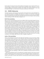
Repeat steps 6 through 10 and use the table and image to name the geometry as follows:
Part number
Name
1
bin
2
robot base
3
long arm
4
short arm
5
long conveyor
6
short conveyor
7
rectangle part
8
Note
Do not assign a rigid body to item 8.
Click Apply to create an object without closing a dialog box.
Run the simulation to see the results and then stop the simulation.
Notice all of the assigned geometry is now affected by gravity.
Prevent floors and surfaces from falling
To prevent a rigid body from falling you need to create a fixed joint. Fixed joints can be
used to:
Fix geometry in the coordinate system.
Attach two pieces of geometry and not allow movement.
1. Choose Home tab→Mechanical group→Fixed Joint
.
2. In the Rigid Bodies group, highlight Select Attachment.
3. In the graphics window, select Rigid Body: plant floor.
Note Do not select a base for this example.
4.
5. In the Name group, type floor bolts.
6. Click OK.
7. Run the simulation to see the results and then stop the simulation.
The plant floor is now fixed in the coordinate system and will not fall due to
gravity. The falling objects will pass through the floor until the collision body
command is used later.
8. Repeat steps 1 through 4 and name the fixed joints as follows:
Part number
Name
5
long conveyor bolts
6
short conveyor bolts
9.
10. Run the simulation to see the results and then stop the simulation.
The conveyors and floor remain in place. All other components are affected by
gravity and pass through the fixed objects
Fix model components together
Use the fixed joint command to connect geometry. In the fixed joint dialog box, assign both
an attachment and a base object to link the pieces together.
1. Choose Home tab→Mechanical group→Fixed Joint
.
2. In the Rigid Bodies group, highlight Select Attachment.
3. In the graphics window, select Rigid Body: robot base.
4. In the Rigid Bodies group, highlight Select Base.
5. In the graphics window, select Rigid Body: plant floor.
6. In the Name group, type robot bolts.
7. Run the simulation to see the results and then stop the simulation.
The rigid bodies robot base and plant floor are now physically linked together.
Create rotational motion joints
Use a hinge joint to create rotating joints. The motion of the joint is restricted to rotating
around a single axis that you select. You will create hinge joints for the robot arms in the
model.
1. Choose Home tab→Mechanical group→Hinge Joint
.
2. In the Rigid Bodies group, highlight Select Attachment.
3. In the graphics window, select Rigid Body: long arm.
4. In the Rigid Bodies group, highlight Select Base.
5. In the graphics window, select Rigid Body: robot base.
6. In the Axis and Angle group, use the Specify Axis Vector drop-down to select XC.
7. In the Axis and Angle group, highlight Specify Anchor Point.
8. In the graphics window, select the center point of the hole in long arm.
9. In the Name group, type base joint.
10. Click OK.
11. Run the simulation to see the results and then stop the simulation.
The motion of the long arm is now restricted to revolving around the joint axis.
12. Repeat steps 1 through 10 to create a second hinge joint. Use the following:
o In the Rigid Bodies group, set short arm as the attachment and long arm as
the base.
o
In the Axis and Angle group, set the Axis Vector to --XC and set the Anchor
Point to the center point of the hole in long arm.
o Name the joint arm joint.
13. Run the simulation to see the results and then stop the simulation.
Both robot joints are limited to rotational motion. Gravity will still cause the joints
to collapse until you add actuators in the next lesson.
Create linear motion joints
Use a sliding joint to create a joint that is restricted to linear motion along one axis.
1. Choose Home tab→Mechanical group→Sliding Joint
2. In the Rigid Bodies group, highlight Select Attachment.
3. In the graphics window, select Rigid Body: bin.
4. In the Rigid Bodies group, highlight Select Base.
5. In the graphics window, select Rigid Body: plant floor.
.
6. In the Axis and Offset group, highlight Specify Axis Vector, use the Specify Axis
Vector drop-down to select XC.
7. In the Name group, type bin track.
8. Click OK.
9. Run the simulation.
10. Drag and drop the bin to verify its motion is restricted to motion in the X direction.
11. Stop the simulation.
12. Close the part without saving.
You completed the activity.