Volume 4 fuel cells and hydrogen technology 4 02 – current perspective on hydrogen and fuel cells
Bạn đang xem bản rút gọn của tài liệu. Xem và tải ngay bản đầy đủ của tài liệu tại đây (9.67 MB, 35 trang )
4.02
Current Perspective on Hydrogen and Fuel Cells
K Burke, NASA Glenn Research Center, Cleveland, OH, USA
Published by Elsevier Ltd.
4.02.1
4.02.1.1
4.02.1.1.1
4.02.1.1.2
4.02.1.1.3
4.02.1.1.4
4.02.1.1.5
4.02.1.1.6
4.02.1.2
4.02.1.3
4.02.1.4
4.02.1.4.1
4.02.1.4.2
4.02.2
4.02.2.1
4.02.2.2
4.02.2.3
4.02.3
4.02.3.1
4.02.3.1.1
4.02.3.1.2
4.02.3.1.3
4.02.3.1.4
4.02.3.1.5
4.02.3.2
4.02.3.2.1
4.02.3.2.2
4.02.3.2.3
4.02.3.2.4
4.02.3.2.5
4.02.4
References
Space Applications of Hydrogen
Space Propulsion
Atlas–Centaur
Apollo Saturn
Space Shuttle
Delta IV
Other LH2/LOX-powered rockets
Advanced space propulsion technology
Space Battery Power and Energy Storage – NiH2 Batteries
Astronaut Environmental Control and Life Support
Scientific Instrument Cooling
Wide-Field Infrared Survey Explorer
Planck
Space Applications of Fuel Cells
Gemini
Apollo
Space Shuttle
Other Current Uses of Hydrogen and Fuel Cells
Current Uses of Hydrogen
Ammonia production
Oil refinery use
Methanol production
Other chemical manufacturing
Other uses
Current Uses of Fuel Cells
Electric power generation
Backup power supplies
Portable electronics
Motor vehicles
Other markets
Conclusion
29
30
30
30
32
34
36
37
39
42
42
43
43
45
45
48
49
50
51
52
52
53
53
54
56
58
58
58
59
61
62
62
4.02.1 Space Applications of Hydrogen
The general public in recent years has been exposed more and more to the topics of hydrogen and fuel cells, and with good reason.
Worldwide concern about the diminishing supply of hydrocarbon fuels that play a fundamental role in the world energy mix and an
equally worldwide concern over the effects on the world’s environment of burning hydrocarbon fuels are two compelling reasons
why hydrogen and fuel cells are frequent topics in the world’s daily news.
Even though hydrogen is produced in great quantities industrially, the general public has little or no direct experience with hydrogen,
so the public’s general knowledge is limited to film footage of the Hindenburg burning and crashing and rockets violently leaving the
launch pad. The gap in knowledge is filled with instinctual suspicion and fear of the unknown. This current public perspective on
hydrogen is changing as more information about hydrogen and a ‘hydrogen economy’ is available. Over time, the image of hydrogen as
a future potential fuel in the public mindset is becoming less fearsome and more appreciated for its unique and beneficial characteristics.
Hydrogen is the ‘cleanest’ of all fuels because as it is oxidized (burned), it produces only water. Hydrogen is abundant over the
entire planet, but because of hydrogen’s reactivity, it is rarely found in its pure gaseous state. Hydrogen is readily produced from
methane, or by the electrolysis of water. For its mass, hydrogen packs a lot of energy; a fact that makes it a highly used fuel for
rockets. The public is largely unaware of how critical hydrogen is to the production of commonly used commodities such as
gasoline and fertilizer. This is probably because the hydrogen is produced where it is used, at industrial sites well beyond public view
and awareness. Hydrogen today is largely produced from natural gas which is primarily obtained from nonrenewable sources as are
other hydrocarbon fuels.
One of hydrogen’s uses that has been widely appreciated is its use for space travel. Hydrogen has been critical to both the
propulsion of spacecraft and the generation of electrical power while in space. Hydrogen is widely used by the United States,
Comprehensive Renewable Energy, Volume 4
doi:10.1016/B978-0-08-087872-0.00402-9
29
30
Current Perspective on Hydrogen and Fuel Cells
Table 1
Rocket propellant performance comparison
Oxidizer
Fuel
Mixture ratio
fuel to oxidizer
Specific impulse
(s, sea level)
Density impulse
(kg-s l−1, SL)
Liquid Oxygen
Liquid hydrogen
Liquid methane
Ethanol + 25% water
Kerosene
Hydrazine
Monomethyl hydrazine
Unsymmetrical dimethyl hydrazine
5.00
2.77
1.29
2.29
0.74
1.15
1.38
381
299
269
289
303
300
297
124
235
264
294
321
298
286
Notes: Specific impulses are theoretical maximum assuming 100% efficiency; actual performance will be less.
All mixture ratios are optimum for the operating pressures indicated, unless otherwise noted.
LO2/LH2 mixture ratios are higher than optimum to improve density impulse.
Where kerosene is indicated, the calculations are based on n-dodecane.
Europe, and Japan for rocket propulsion, and will continue to be in the future. Hydrogen’s use in fuel cells to make electrical
power for spacecraft for nearly 40 years has been and continues for many to be a fascinating and mysterious process. The current
development of commercial uses for fuel cells that use hydrogen has captured the public’s attention and hopes that the
combination of hydrogen and fuel cells might one day help reduce the concerns about the world’s future energy and
environment.
4.02.1.1
Space Propulsion
Hydrogen use as a chemical propellant is unquestionably the most important space application of hydrogen. In terms of mass of
hydrogen used, the use of hydrogen propellant dwarfs all other space applications of hydrogen combined. The reason for the use of
hydrogen is that hydrogen is the most efficient propellant. Specific impulse is a measure of the change of momentum per unit
weight of the propellant on Earth. The higher the specific impulse, the less the weight of propellant needed. Table 1 shows a
comparison of liquid fuel rocket propellants [1]
4.02.1.1.1
Atlas–Centaur
The Atlas–Centaur rocket was the first rocket to use the combination of liquid hydrogen/oxygen (LH2/LOX) for propulsion. This
rocket’s second stage, Centaur, used the RL10 LH2/LOX rocket engine shown in Figure 1. The RL10 manufactured by Pratt and
Whitney was the first engine to use LH2/LOX. Figure 2 shows a simplified flow schematic of the RL10 engine. The RL10 used liquid
hydrogen to cool the engine nozzle, and the heat absorbed by the liquid hydrogen caused the hydrogen to expand, after which it
flowed through a turbine. The rotation of the turbine was mechanically coupled to the LH2 and LOX pumps which pump the
propellants to the combustion chamber. This synergy of design made the engine lightweight and very reliable. The RL10 was first
run in July 1959, and was first flight tested with the Centaur on 27 November 1963. The test flight was delayed to allow for the
mourning of President Kennedy, who was shot days earlier [4]. Upgraded versions of the RL10 are used to currently launch
Atlas–Centaur rockets and on the upper stage of the Delta IV rocket being used currently.
Figure 3 shows a cutaway view of the Centaur rocket. The Centaur rocket uses helium to pressurize the hydrogen and oxygen
propellants. The pressurized propellants rigidize the structure of the rocket which minimizes the mass of the rocket structure. Using
pressurized propellants to rigidize a rocket’s structure was initially demonstrated during a US Air Force missile project called
MX-774. Although this project was cancelled before the development was completed, Charlie Bossart, the MX-774 designer, applied
this knowledge to the design of the Atlas. Later, this ‘pressure-stabilized’ approach was used by Krafft Ehricke as a key design element
of the Centaur [4]. Figure 4 shows the dual engine version of the Centaur upper stage.
Together, the RL10 LH2/LOX rocket engine and the lightweight Centaur structure gave NASA a lightweight powerful upper stage.
The powerful Centaur upper stage when mated to the lightweight Atlas provided NASA with a launch vehicle capable of putting
payloads beyond low Earth orbit (LEO; 160–2000 km altitude) and out into space (>2000 km altitude). Figure 5 shows an
exploded view of an Atlas–Centaur rocket.
4.02.1.1.2
Apollo Saturn
The Apollo missions to the moon used the Saturn V rocket. The Saturn V was a three-stage rocket. The first stage was to carry the
Saturn rocket to an altitude of ∼200 000 feet (61 km). It used five engines that burned kerosene and liquid oxygen as propellant to
produce 7 600 000 lbs (34 000 000 N) of thrust. There were no LH2/LOX engines then (or now) capable of producing such
enormous thrust. Its second and third stages which burned sequentially used LH2/LOX. The payloads to be launched required
more powerful LH2/LOX engines (200 000 lbs/890 000 N of thrust) than the RL10 LH2/LOX engine (20 000 lbs/89 000 N of
thrust). This required the development of the J-2 LH2/LOX by Rocketdyne shown in Figure 6.
Current Perspective on Hydrogen and Fuel Cells
31
Figure 1 Pratt and Whitney RL10 [2].
LH2 pump
Turbine
LOX pump
Control
valves
Combustion
Chamber
Heat
exchanger
Nozzle
Figure 2 RL10A-3 rocket engine flow schematic [3].
The second stage of the Saturn V, called SII, used five J-2 engines to provide 1 million pounds of thrust. The SII stage had a
diameter of 10 m and a length of ∼24.9 m. Filled with propellants, its gross mass was ∼480 000 kg, and when empty, a mass of
∼36 000 kg. The burn time for the second stage was 367 s [9]. Figure 7 shows an illustration of the SII stage, and Figure 8 shows the
SII stage being hoisted into a test stand at the NASA Stennis Space Center.
The third stage of the Saturn V used one J-2 engine, which provided ∼200 000 lbs of thrust. The SIII stage had a diameter of 6.6 m
and a length of ∼17.8 m. Filled with propellants, its gross mass was 119 900 kg, and when empty, a mass of ∼11 000 kg. The burn
time for the second stage was 475 s [12].
An upgraded version of the J-2 engine, called J-2X, is being currently developed for NASA for further exploration of the Moon and
Mars. The J-2X with 294 000 lbs of thrust will be more powerful than the J-2 engine. The J-2X engine requirements call for an exit
32
Current Perspective on Hydrogen and Fuel Cells
Equipment
module
Stub adapter
LH2 tank
Fuel slosh
Radiation
shield
LOX tank
Baffle
Intermediate
bulkhead
Propellant
utilization
probe
Intermediate
adapter
Helium
bottle
RL10 engines
Figure 3 Cutaway view of Centaur upper stage [5].
Figure 4 Dual engine Centaur upper stage. From NASA Image Exchange, ID No. KSC-00PP-0426, NASA Kennedy Space Center (dual engine Centaur
Photo). [6].
diameter of ∼47 cm, a length of 72.8 cm, and a mass of 2477 kg [13]. The J-2X is to be used in the upper stage of the NASA Space Launch
System (SLS) which will launch a crew and cargo into LEO. The NASA SLS will also be used to lift exploration craft beyond Earth orbit.
4.02.1.1.3
Space Shuttle
The Space Shuttle was launched using a combination of two solid rocket motors and three LH2/LOX engines. The solid rocket
motors burn a solid propellant and cannot adjust their level of thrust, whereas the LH2/LOX engines use liquid propellants and
Current Perspective on Hydrogen and Fuel Cells
Juno
spacecraft
Forward
load
reactor
RL10
Centaur
engine
Payload
fairing
Launch
vehicle
adapter
Atlas V booster
Solid rocket
boosters
33
Centaur
Boat tail
Centaur interstage adapter
Booster interstage adapter
RD-180
engine
Figure 5 Atlas–Centaur rocket [7].
Vehicle effectivity
J-2 engine
11.1 FT
6.8 FT
SA-201
THRU
SA-203
SA-204 THRU
SA-207&SA-501
THRU SA-503
SA-208 &
subsequent;
and SA-504 &
subsequent
Thrust (altitude)
200 000 lb 225 000 lb 230 000 lb
Thrust duration
500 s
500 s
500 s
Specific impulse
421 min
418 min
419 min
(lb-s/lb)
3 480 lb
3 492 lb
3 480 lb
Engine weight dry
Engine weight
3 609 lb
3 609 lb
3 621 lb
burnout
Exit to throat area
27.5:1
27.5:1
27.5:1
ratio
LOX and LH2 LOX and LH2 LOX and LH2
Propellants
5.00 ± 2(%) 5.50 ± 2(%) 5.50 ± 2(%)
Mixture ratio
Contractor: NAA/Rocketdyne
Vehicle application:
SAT IB/S-IVB STAGE (one engine)
SAT V/S-II STAGE (five engines)
SAT V/S-IVB STAGE (one engine)
Figure 6 Rocketdyne J-2 rocket engine. From NASA Image Exchange, ID No. MSFC-9801770, NASA Marshall Space Flight Center (J2 Engine Slide).
[8].
have their thrust adjusted during the ascent. Unlike the Saturn V where the first stage is nearly complete with its burn when the
second stage starts its burn, the Space Shuttle’s propulsion combination propelled the Space Shuttle simultaneously until the solid
rocket motors completed their burn. The solid rocket motors then separated from the Space Shuttle and fell back to Earth where they
were recovered, refurbished, and reused. The three LH2/LOX engines then continued to burn, eventually lifting the Space Shuttle
into LEO. Figure 9 shows the Space Shuttle shortly after liftoff with both the solid rocket motors and the LH2/LOX engines
operating. The large orange tank shown in Figure 9 is the LH2/LOX storage tank. This tank was the only expendable portion of the
Space Transportation System, separating from the Space Shuttle after the LH2/LOX engines completed their burn. Unlike the Saturn
V and all previous rockets, the Space Shuttle was reusable. Following its 1–2-week mission, the Space Shuttle reentered the Earth’s
atmosphere, glided, and then landed on a landing strip.
34
Current Perspective on Hydrogen and Fuel Cells
Second stage (S-II)
Saturn V
Manhole cover
LH2 Tank
pressure line
Cable tunnel
Gas distributor
LOX vent line
Mast
Second
separation
plane
Work
platform
Fuel level sensor
J-2 engine
Heat shield
Ring slosh baffle
LOX sump
LH2 suction line
Ullage rocket
Saturn V
Figure 7 Saturn V second stage, SII. From Marshall Space Flight Center Image Exchange, Photo No. 9801810. />MEDIUM/9801810.jpg [10].
Figure 8 SII lifted into test stand. From NASA Image Exchange, ID No. 67-701-c, NASA Stennis Space Center (SII stage of Saturn V rocket photo). http://
www.ssc.nasa.gov/sirs/photos/history/low/67-701-c.jpg [11].
The Space Shuttle Main Engine (SSME) was unique, in that it was the only reusable LH2/LOX engine in the world. It was
designed for 7.5 h of operation over an average life span of 55 starts [15]. The SSME was much more powerful than the J-2 engine
(470 000 lbs of thrust (at vacuum) vs. 200 000 lbs). The SSME consumed 4420 kg per minute of LH2 and 26 450 kg per minute of
LOX for ∼8.5 min. The SSME had an exit diameter of 230 cm, a length of 427 cm, and a mass of 3526 kg [16, 17]. Figures 10 and 11
show the SSME [18, 19]. The SSME is one of the rocket engines being considered for the first stage of NASA’s new SLS.
4.02.1.1.4
Delta IV
The Delta family of rockets started with the first launch of a Delta rocket on 13 May 1960. The early Delta rockets did not use LH2 as
a propellant. The Delta rocket evolved through continuous improvement from a Delta A rocket in 1962 through a Delta N rocket in
Current Perspective on Hydrogen and Fuel Cells
35
Figure 9 Space Shuttle after Liftoff. From NASA Image Exchange, ID No. STS062(S)055, NASA Johnson Space Center. />STS062(S)055.jpg [14].
Figure 10 Space Shuttle Main Engine. From NASA Image Exchange, ID No. KSC-04PD-1643, NASA Kennedy Space Center. />photos/2004/low/KSC-04PD-1643.gif [18].
36
Current Perspective on Hydrogen and Fuel Cells
Figure 11 Test firing of the SSME. From NASA Image Exchange, Photo No. MSFC-7995081. />MEDIUM/7995081.jpg [19].
1972. This improvement continued through 1972–89 with Delta Series 904, 1000, 2000, 3000, 4000, and 5000. This in turn was
followed by the Delta II Series 6000 and 7000 from 1989 through 2000. After two failures, a Delta III was successfully launched on
23 August 2000 [20]. The Delta III used the Pratt and Whitney RL10 LH2/LOX engine for the upper stage. This was however the only
successful launch of the Delta III as it was quickly replaced by the higher performance Delta IV. The first Delta IV was launched on 20
November 2002 [21]. The Delta IV series continues to be launched. The Delta IV series uses the RS-68 LH2/LOX engine for its first
stage. The Delta IV-4M (Medium Lift) uses a single RS-68 LH2/LOX engine, whereas the Heavy Lift version uses three RS-68 LH2/
LOX engines [22].
The RS-68 LH2/LOX rocket engine was developed by Rocketdyne in 1998. The RS-68 is the largest and most powerful LH2/LOX
engine in the world. The RS-68 is more powerful than the SSME engine (758 000 lbs of thrust vs. 470 000 lbs). The RS-68 is ∼244 cm
in diameter and 521 cm in length, and has a mass of 6761 kg [23]. Figure 12 shows the RS-68 being test fired [24].The RS-68 is a
candidate for possible use in NASA’s new SLS.
4.02.1.1.5
Other LH2/LOX-powered rockets
Only recently, nations other than the United States have started to produce LH2/LOX engines. The Japanese have produced two
engines which are used for first and second stages. The LE-5 is used for the second stage, and had its first flight in 1986. The LE-5
produces 23 100 lbs of thrust and has a diameter of 2.49 m, a length of 2.68 m, and a mass of 245 kg [25]. Figure 13 shows the LE-5
[26]. Japan also produced the LE-7 designed for a first stage, and had its first flight in 1994. The LE-7 produces 242 000 lbs of thrust
and has a diameter of 4 m, a length of 3.4 m, and a mass of 1714 kg [27]. Figure 13 also shows the LE-7 [26]. Japan’s H-II unmanned
expendable launch vehicle uses one LE-7A engine in its first stage and one LE-5 is used on the upper stage.
Snecma Moteurs (France) has produced the Vulcain, an LH2/LOX engine designed for a first stage, and had its first successful
flight in 1997 [28]. The Vulcain produces 256 760 lbs of thrust and has a diameter of 1.76 m, a length of 3.0 m, and a mass of
1700 kg [29]. Figure 14 shows the Vulcain [28]. The Ariane 5 launch vehicle uses a single Vulcain as its first stage engine.
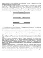
The Energia–Buran shown in Figure 15(a) is a Russian-built launch system whose second stage (shown in Figure 15(b)) is fueled
by LH2/LOX. The second stage is powered by four RD-0120 engines shown in Figure 16. The RD-0120 was similar in performance
to the US-built SSME used in the US Space Shuttle. The Energia flew only two flights. The first of these was on 15 May 1987 with
Polyus spacecraft as the payload. The second and final launch was with the Russian shuttle vehicle, Buran, on 15 November 1988.
The fall of the Soviet Union ended the flights of the Energia and the use of the RD-0120 engines. In the 1990s, several other
launchers were designed with an Energia core stage, but none were ever built. Starting in 2001, another Russian LH2/LOX engine,
the RD-0146, was developed, but as of 2010 had not yet flown.
Current Perspective on Hydrogen and Fuel Cells
37
Figure 12 RS-68 test firing. From NASA Image Exchange, Photo No. MSFC-0700063. />148709main_d4_testing_08.jpg [24].
LE-5/5A/5B
(LOX/LH)
LE-7
(LOX/LH)
Figure 13 Japan’s LE-7 LH2/LOX engine [25].
4.02.1.1.6
Advanced space propulsion technology
Unlike all previous mentioned rocket engines that use hydrogen, advanced space propulsion that uses hydrogen does not combust
the hydrogen. Instead, the hydrogen is heated to high temperatures from high-energy sources and then the hydrogen exits the engine
at a high velocity. The specific impulse from these engines varies depending on the temperature to which the hydrogen is heated, but
in general the specific impulse is much higher than that of conventional hydrogen/oxygen engines. One common drawback to this
38
Current Perspective on Hydrogen and Fuel Cells
Figure 14 Vulcaine rocket engine [28].
(a)
Figure 15 (a) Energia–Buran. (b) Energia second stage [30, 31].
(b)
Current Perspective on Hydrogen and Fuel Cells
39
Figure 16 RD-0120 rocket engine [32].
propulsion technology is that a high-power, high-energy source is needed to heat the hydrogen. There are several types of advanced
rocket engines that take this approach.
Hydrogen arcjet engines use an electric arc to directly heat the hydrogen which is then expanded through a rocket nozzle. The
engines have been operated with electric power sources ranging from 0.5 to 30 kW and have a characteristic specific impulse in the
range of 1000–1500 s [33]. Unlike chemical rockets which burn powerfully for short periods of time, these engines operate by
providing small amounts of thrust over long periods of operation. These engines minimize the amount of propellant needed for an
overall mission, but are unsuitable for lifting rockets from the Earth’s surface. Instead, these engines provide efficient propulsion
after the payload is already in space. This technology was investigated in the 1960s and more recently in the 1990s, and has been
considered for orbital transfer and for satellite attitude control and orbit maintenance.
Nuclear thermal rocket (NTR) engines use heat from a nuclear reactor to heat the hydrogen which is then expanded through a
rocket nozzle. In 1959, the first ground test of NTR technology was the test of ‘Kiwi-A’, a proof-of-concept test engine named after
the New Zealand flightless bird [34, 35]. Nuclear Engine for Rocket Vehicle Application (NERVA), shown in Figure 17, was
developed during the 1960s as an upper stage engine to the Apollo Saturn V booster. The initial test run of the engine was in
September 1964. The engine had a specific impulse of 850 s and produced a thrust of 75 000 lbf. A more powerful derivative,
Phoebus, was capable of producing a thrust of 250 000 lbf. In 1972, the development of a flight test model of the NERVA was
cancelled when US plans for manned Mars exploration were cancelled by President Nixon.
The Variable Specific Impulse Magnetoplasma Rocket (VASIMR) ionizes and heats a gas into a hot plasma using radiofrequency
energy. The heated plasma is then focused and directed using magnetic fields to generate thrust as shown in Figure 18. VASIMR is
capable of using different gases (including hydrogen). VASIMR has demonstrated a very high-specific impulse of 4000 to over
10 000 s depending on propellant used [38], indicating that 90% or more of the propellant weight could be saved, a tremendous
advantage, especially for long space voyages. Like the hydrogen arcjet, it provides a low amount of thrust over a long period of time.
One serious drawback to this promising technology is that the VASIMR requires a very high-power electric source, and the mass of
the power source offsets its propellant advantage. Long planetary trips to date have used electric power sources that are much less
powerful than what is needed by VASIMR. Future, possibly very high-power nuclear electric sources, may allow this technology to be
fully exploited. Figure 19 shows an artist’s illustration of a VASIMR-powered spacecraft concept.
4.02.1.2
Space Battery Power and Energy Storage – NiH2 Batteries
Nickel–hydrogen batteries were developed to increase energy density and capacity in rechargeable battery technology for aerospace
energy storage. The nickel–hydrogen cells are a hybrid technology, combining elements from both batteries and fuel cells. The
nickel–hydrogen cells utilize the nickel hydroxide electrode from nickel–cadmium cells and a platinum hydrogen electrode from
40
Current Perspective on Hydrogen and Fuel Cells
Shield
Pressure
vessel
Reflector
NERVA reactor
based on NRX A1
Graphite felt lateral support
Top-loaded core
Radial
support
Reactor
Figure 17 NERVA rocket engine. From NASA Image Exchange, Photo No. MSFC–9902054, [36].
50 kW VASIMR laboratory experiment
Magnetic nozzle directs plasma flow
Plasma heated to millions of degrees Kelvin
Magnetic coils confine the ionized plasma
Helicon antenna ionizes gas to plasma
Quartz tube confines gas
Gaseous H2 or He Injection
Figure 18 VASIMR engine test [37].
fuel cell technology to create a chemistry without the issues and limitations inherent with the cadmium electrode. The nickel–
hydrogen chemistry has better long-term cycle life and specific energy over the standard aerospace nickel–cadmium battery, though
having a poorer volumetric energy density.
The electrochemical reactions that occur during discharge are as follows:
NiOOH þ H2 O þ e− → Ni ðOHÞ 2 þ OH− ðat the nickel electrodeÞ
ðat the hydrogen electrodeÞ
=2 H2 þ OH− → H2 O þ e−
NiOOH þ 1 =2 H2 → Ni ðOH Þ 2
ðoverall reaction during dischargeÞ
1
Current Perspective on Hydrogen and Fuel Cells
41
Figure 19 VASIMR-powered rocket concept [39].
Seal
Positive feedthrough
Pressure vessel
Top-end plate
Negative bus bar
Positive bus bar
Electrode stack
Bottom-end plate
Weld ring
Insulating
washers
Negative feedthrough
Fill port
Figure 20 NTS-2 nickel–hydrogen cell. From Battery Workshop, NASA Technical Reports Server, p. 246. />nasa.gov/19940023606_1994023606.pdf [41].
The reactions are reversed during charge. As a nickel–hydrogen cell cycles, hydrogen is produced on charge and consumed during
discharge. The cell is contained within a hermetically sealed, Inconel pressure vessel that envelopes the electrodes and accommo
dates the pressurized hydrogen. Cells are typically designed to operate between 50 and 1000 psi. The nominal operating voltage for
a nickel–hydrogen cell is 1.25 VDC, about the same as for a nickel–cadmium cell.
The development of nickel–hydrogen cells was started by COMSAT Laboratories in 1970 [40]. After the initial demonstration of the
feasibility of the nickel–hydrogen cell, INTELSAT funded COMSAT Laboratories to develop a 50 A-h cell, and in 1975, this development
had progressed to the point that the US Naval Research Laboratory funded COMSAT Laboratories to develop a 35 A-h nickel–hydrogen
cell for use on the US Navy’s Navigation Technology Satellite (NTS-2) spacecraft shown in Figure 20 [40, 42]. The NTS-2, launched in
1977, was the first use of nickel–hydrogen battery technology in space. Nickel–hydrogen cells were then put in service on Intelsat V, VI,
and VII satellites from 1983 through 1996 [43, 44]. Separate designs evolved to address LEO operations. In 1990, the Hubble telescope
launched as the first LEO satellite using nickel–hydrogen batteries, after which nickel–hydrogen batteries were used for numerous LEO
missions. In the mid 1980s, the International Space Station (ISS) power system was designed with the largest ever series-connected
nickel–hydrogen battery Orbital Replacement Units (ORUs), as shown in Figure 21, to provide energy storage during the LEO eclipse
period [45]. The first set of ISS battery ORUs was launched in 2000. The ISS nickel–hydrogen batteries have an operational life of 6.5 years.
42
Current Perspective on Hydrogen and Fuel Cells
Deadface load
Top cover plate
Bus bar cell interconnect
Strain gauge
pressure sensor
Instrumentation harness
Enclosure
Graphite
cell sleeve
Heater
Fuse
assembly
Nickel hydrogen
battery cell
Acme screw
Power connector
Battery signal
conditioning and
control module
Data
connector
Status indicator
Multiple layer
insulation
EVA tether
Microhandle
Figure 21 ISS NiH2 battery ORU [45].
Early nickel–hydrogen cells were packaged in individual pressure vessels (IPVs) shown in Figure 20 [41].Subsequent develop
ment packaged multiple cells within a single pressure vessel (SPV). These designs addressed the low-energy density of
nickel–hydrogen systems. These were known as common pressure vessel (CPV) or SPV designs.
Nickel–hydrogen cell technology started to become obsolete in the 2000s with the introduction of lithium-ion battery
technology that had significantly better specific energy, energy density, lower self-discharge rates, and higher columbic efficiency.
Unlike nickel–hydrogen, which was almost exclusively an aerospace technology, the commercial development of lithium-ion
technology for small portable electronics provided the added push, advancing lithium-ion technology and accelerating the
displacement of nickel–hydrogen technology in space.
4.02.1.3
Astronaut Environmental Control and Life Support
As manned space missions have gradually increased in number of crew and length in time, the advantage of recycling life supporting
resources such as water and oxygen versus supplying these resources as expendable (not recycled) becomes more and more
compelling when comparing the mass of spacecraft using recycling system with the alternative expendable systems. The disadvan
tage to recycling systems is that they generally are not as reliable as expendable systems; they also tend to consume another valuable
resource, electrical power. Water electrolysis equipment that contributes to ‘closing the oxygen loop’ has been developed and is
being used on the ISS. Water electrolysis splits water into hydrogen and oxygen. The oxygen contained within the water is recycled,
while the hydrogen is either vented overboard into space or used to reduce carbon dioxide. The reduction of carbon dioxide with
hydrogen produces water and either methane or amorphous carbon black. The carbon dioxide reduction process that reduces
carbon dioxide to water vapor and methane is called the Sabatier CO2 reduction system [46]. Another alternative carbon dioxide
reduction process that reduces carbon dioxide to water vapor and carbon black is called the Bosch CO2 reduction system. The water
vapor produced during the reduction process is subsequently recovered and split into hydrogen and oxygen by water electrolysis. A
block diagram of the advanced life support system is shown in Figure 22.
4.02.1.4
Scientific Instrument Cooling
Cooling technologies are required for the high-performance detection of electromagnetic radiation of millimeter to nanometer
wavelengths. Radiation detectors are subject to background noise that unless substantially reduced can make precise detection
impossible. Radiation detectors are cooled to cryogenic temperatures to reduce the background noise, sometimes referred to as the
background limit, caused by thermal energy of the detectors themselves. This applies for many types of radiation detectors. For
infrared detectors looking through the Earth’s atmosphere, the background noise is frequently determined by the atmosphere, but
Current Perspective on Hydrogen and Fuel Cells
Shower,
handwasher,
etc.
Hygiene H2O
water
processor
Hygiene
water
storage
H2O
O2
generation
H2O
Habitat
Urine
processor
CO2
reduction
CO2
removal
Brine
Condensing
heat
exchanger
Potable
water
storage
O2
H2
Brine
Urinal
43
Potable
water
processor
H2O
Solid C
or CH4
Trace
contaminant
control
H2O
Process atmosphere
Figure 22 Advanced environmental control and life support for space [47].
for infrared instruments in space, above the atmosphere, the background limit is determined by the instrument itself which glows
with thermal infrared radiation. These infrared instruments are cooled to less than 1 K. To provide such low-temperature cooling
requires a refrigerant capable of working at these low temperatures, typically helium or hydrogen.
4.02.1.4.1
Wide-Field Infrared Survey Explorer
On 14 December 2009, NASA launched the Wide-Field Infrared Survey Explorer (WISE). The WISE, shown in Figure 23, circles the
Earth, from pole to pole, 15 times each day, taking pictures of the sky every 11 s. Its mission is to observe the universe in the 3–25 μm
wavelength [49]. The WISE cryostat, shown in Figure 24, is a two-stage, solid hydrogen cryostat that cools the satellite’s detectors to
7.6 K. The solid hydrogen cryostat is expected to last about 10 months after which the satellite’s mission will be finished. By cooling
the optics and detectors to such a low temperature, WISE will be able to measure the infrared glow of celestial objects with a
sensitivity hundreds of times more than any previous radiometer. WISE will be able to measure the infrared radiation of asteroids in
our solar system between Mars and Jupiter and provide the first good estimate of their size distribution.
4.02.1.4.2
Planck
The Planck spacecraft shown in Figure 25 was launched on 14 May 2009 by the European Space Agency (ESA). Planck’s instruments
will measure minute differences in the background radiation of space. The background radiation is residual radiation from the Big
Figure 23 WISE satellite. From Jet Propulsion Laboratory Photo Journal, Photo No. PIA12011. [48].
44
Current Perspective on Hydrogen and Fuel Cells
Figure 24 WISE hydrogen cryostat. From Jet Propulsion Laboratory Photo Journal, Photo No. PIA12316. />PIA12316_modest.jpg [50].
Figure 25 Planck spacecraft [51].
Bang creation of the universe. These minute differences are measured in millionths of a degree Kelvin about the observable
temperature difference measured from Earth of the heat of a rabbit sitting on the moon [52]. To obtain this extraordinary sensitivity,
the radiation detectors must be cooled to 0.1°K. The cooling system for the Planck spacecraft uses a three-stage cooler. The second
cooling stage of the Planck spacecraft shown in Figure 26 uses a hydrogen sorption cooler. Gaseous hydrogen at low pressure is
absorbed by a metal hydride sorbent bed. When the metal hydride sorbent bed has absorbed the hydrogen, the bed is then heated to
release the hydrogen, creating high pressure hydrogen. The high pressure hydrogen is precooled, then expanded through a
Joule–Thompson expander which cools the detectors to below 20 K. The expanded hydrogen is reabsorbed by the metal hydride
sorbent bed so that it can be recompressed at the start of another cooling cycle. The heat switch is activated to cool the sorbent bed
after the bed has been heated to release the hydrogen. Cooling the sorbent bed prepares it to reabsorb hydrogen at the start of the
next cooling cycle.
Current Perspective on Hydrogen and Fuel Cells
45
Radiator
Heat
switch
High pressure
hydrogen
Precooler
Sorbent bed
Gaseous
hydrogen at
low P
J-T
Liquid
refrigerant
Heat from sensors
Figure 26 Planck cooling system [53].
4.02.2 Space Applications of Fuel Cells
Fuel cell technology was put into the world public spotlight in dramatic fashion by NASA which chose to use hydrogen/oxygen fuel
cells to provide critical electrical power to its manned spacecraft. While earlier development efforts were looking at fuel cells for
various terrestrial power applications, these efforts gained little public notice, but the world public watched as astronauts were
launched into space, voyaged to the moon, and returned to Earth, powered in no small measure by a mysterious, new ‘space-age’
technology called fuel cells. NASA first used fuel cells for powering the Gemini spacecraft during takeoff and while in orbit. Besides
providing the electricity for the Gemini spacecraft, fuel cells were also used to provide power for the Apollo spacecraft and the Space
Shuttle. The choice of fuel cells as the power source was because fuel cells offered the lightest electrical power source. Also the water
produced by the fuel cells used for the Apollo and the Space Shuttle was suitable for astronauts to use which saved the weight of
bringing a separate source of water. For each spacecraft, the reactant use was ∼0.33 kg O2 h−1 and 0.04 kg H2 h−1 per kilowatt of
power produced. The water generation was ∼0.37 kg h−1 per kilowatt of power produced.
4.02.2.1
Gemini
On 21 August 1965, the Gemini 5 spacecraft launched the use of hydrogen–oxygen fuel cells for electrical power generation. The use
of fuel cells was still in doubt as late as November 1963 when fuel cell production was stopped due to technical problems. In
January 1964, a meeting at the Johnson Space Center was held to review the development status and decide what to do. It was
decided to redesign the fuel cells and have them ready for the fifth Gemini flight [54]. The Gemini fuel cell system was used on
Gemini 5, 7, 8, 9A, 10, 11, and 12. The Gemini fuel cells were constructed with a polymer membrane which served as the
ion-conductive electrolyte between the cells anode and the cathode plates. This technology served as the precursor for the proton
exchange membrane (PEM) fuel cells that are being developed for many of the fuel cell terrestrial applications that are currently
under development.
The Gemini fuel cell stack, shown in Figure 27, consisted of 32 cells in electrical series. Each cell contained an active area of
360 cm2 (20 cm 18 cm) and used an acid-based PEM as its electrolyte. Three fuel cell stacks were connected electrically in parallel,
shown in Figure 28, and housed in a fuel cell section shown in Figure 29. Each section was about 66 cm in length and 33 cm in
diameter and weighed about 31 kg and produced a maximum of 600 W. Two such fuel cell sections plus an associated reactant
supply system comprise the Gemini fuel cell system shown in Figure 30.
Hydrogen was distributed to each section, and within each section, the hydrogen was manifolded to each of the three cell
stacks. Oxygen was distributed to each section and within each section it was manifolded to each cell stack. The oxygen
compartments of the cells were open to the inside of the section container which was filled with oxygen. The hydrogen and
oxygen were not circulated through the cell stacks, but were ‘dead-ended’ and kept at a constant pressure so that as hydrogen
and oxygen was consumed by the cells, more hydrogen and oxygen was supplied to the cells to maintain the constant
pressure. The water produced by each cell was absorbed by a wick immediately adjacent to the oxygen compartment of each
46
Current Perspective on Hydrogen and Fuel Cells
Coolant out
Coolant in
Coolant tubes
H2 manifold
inlet
O2 current
collector
Cell wicks
(–) Terminal
plate
H2 feed
tubes
Stack tie
rod
Honeycombed
end plate
H2 current
collector
IEM electrode
assembly
(+) Terminal plate
Water separator basin
Hydrogen purge manifold
Figure 27 Gemini fuel cell stack [55].
Figure 28
Gemini stacks before loading into fuel cell section [56].
cell. These wicks transferred the water to the bottom of each cell stack where the water was absorbed by a porcelain gas/
water separator. The water was pushed out of the gas water separator and outside the fuel cell section by the pressure
difference that was controlled between the oxygen and the water. Water was collected in an accumulator so that the water
could be used by astronauts for drinking. Coolant was distributed to each section and within each section the coolant
circulated through the three stacks in series. The coolant was also used to preheat the reactants coming from the supercritical
reactant storage tanks. The Gemini 5 mission data showed that the fuel cell stack sections operated at 25.5–28.1 VDC, and
the current load varied from 9 to 24 A for each section [57].
Current Perspective on Hydrogen and Fuel Cells
Figure 29 Gemini fuel cell section [56].
Accumulator
Main busses
+
Bus
tie
+
H 2O
Electrical
control and monitoring
Water
+ –
Fuel cell section
three stacks
+ –
nt
Fuel
Coola
er
Wat
Coolant
Oxidizer
More sections as needed
Coolant
pump
Reactant
preheater
H2
O2
Radiator
Figure 30 Gemini fuel cell system [56].
47
48
Current Perspective on Hydrogen and Fuel Cells
4.02.2.2
Apollo
Three Apollo fuel cell systems powered the Apollo Command and Service Module until the command module separated from the
service module prior to the command module’s return to Earth. The technology of choice was based on a liquid potassium
hydroxide electrolyte rather than the acid-based PEM polymer that identified the Gemini fuel cells. The main reason for the
change was that the polymers of the early 1960s were not developed to the point at which the endurance demands of the Apollo
missions could be assured. However, since the 1960s, polymer membrane development has continued and advances have been
made to assure many thousands of hours of stable operation in the various terrestrial applications in which PEM fuel cells are
being applied. The first flight for the Apollo fuel cell system was flight AS-202 flown on 25 August 1966 [58]. AS-202 was the
second test flight of the Apollo Command/Service Module launched with the Saturn IB launch vehicle [59]. This flight was
successful and led to the first manned Apollo flight, AS-204. The AS-204 flight tragically claimed the lives of the first three Apollo
astronauts due to a fire in the crew capsule. The flight AS-204 was renamed Apollo 1 in honor of the fallen astronauts. The Apollo
fuel cell system flew on all subsequent Apollo missions, Skylab missions, and the Apollo–Soyuz mission. The fuel cell systems
were located inside the service module and were the only power source for the service module. An auxiliary battery was added to
the service module after the explosion on Apollo 13 disabled the fuel cell reactant system.
The Apollo fuel cell illustrated in Figures 31 and 32 consisted of two nickel plates separated by a Teflon gasket that prevented an
electrical short between the plates and prevented the electrolyte between the plates from leaking outside the cell. Ceramic insulators
in the reactant lines likewise prevented electrical shorting between the cells. A porous nickel electrode within each nickel plate
separated the electrolyte from the hydrogen and oxygen reactants. The reactant pressure was 10.5 psi above the electrolyte pressure
to maintain the separation between the liquid electrolyte and the gaseous reactants. The Apollo fuel cell system used an 85% KOH
electrolyte, and operated at a nominal temperature of 213 °C and a pressure of ∼4 atmospheres. The expansion and contraction of
the electrolyte was accommodated by the flexing of the diaphragm that was at the perimeter of each cell. The pressure of the
electrolyte was maintained by nitrogen which bathed the exterior of each cell. The Apollo fuel cell module shown in Figure 33
Nickel plus nickel
oxide electrode
Nickel backplate
diaphragm section
Reactant in
Oxygen
reactant
cavity
Weld
Reactant out
Hydrogen
reactant
cavity
Nickel electrode
Potassium
hydroxide
Electrolyte seal
Spacer
Electrode area
Diaphragm
Reactant out
Reactant in
Welds
Ceramic insulator
A
A
Figure 31 Apollo fuel cell – Cross section and top views. From Apollo program summary report. JSC-09423, NASA Lyndon B. Johnson Space Center,
April 1975, pp. 4–39. [59] and NASA Apollo Command Module news reference. North American Aviation, 1968,
p. 108. [60].
Current Perspective on Hydrogen and Fuel Cells
Nickel
backplate
diaphragm
section
49
Teflon seal
Oxygen
Nickel + nickel oxide
electrode
Nickel
electrode
Welds
Oxygen
Hydrogen
Potassium
hydroxide
Nitrogen
Nitrogen
Nitrogen
Spacer
Figure 32 Apollo fuel cell – Cross section (two cells). From NASA Apollo Command Module news reference. North American Aviation, 1968, p. 108.
[60].
consisted of a stack of 31 cells in electrical series. Each cell had a diameter of 20 cm. The stack of cells was placed inside a pressurized
nitrogen jacket. Above the stack was an accessory section that contained the hydrogen pump/separator, the coolant pump, the
coolant accumulator, and the reactant pressure controls.
The Apollo fuel cell system shown in Figures 34 and 35 was about 112 cm in length and 57 cm in diameter and weighed about
109 kg.
Three fuel cell systems were connected electrically in parallel to share the electrical load for the Apollo spacecraft. The Apollo fuel
cell system flow schematic is shown in Figure 36. Each fuel cell system was capable of steadily producing 1420 W within the normal
voltage range of the Command Module voltage bus (27–31 VDC).
The Apollo fuel cell system circulated the hydrogen through the cell stack which both removed the water that was formed as well
as the waste heat. The water was condensed from the circulating hydrogen and the condensed water was dynamically separated and
pumped out by hydrogen pump/separator. During the test flights AS202, AS501, AS502 and the flights of Apollo 7, 8 and 9, ∼450 kg
of potable water was produced by the fuel cell systems. Of this, about 60% was consumed directly by the crews. The average mission
power level required from each fuel cell system was 600W, so in the event of two system failures, a single fuel cell system could still
meet the power demands of the mission [65].
4.02.2.3
Space Shuttle
The Space Shuttle was a substantially larger, more versatile, and more complex spacecraft than the Apollo. The nominal power
consumption of the Space Shuttle was 7000 W (plus additional power required for payloads it was carrying) and that of the Apollo
was ∼1690–4260 W. A more highly developed and improved version of the Apollo fuel cell was selected to provide the on-board
power of the Space Shuttle because, while advances in membrane technology had been made by the early 1070s, the potassium
50
Current Perspective on Hydrogen and Fuel Cells
To regulator
Hydrogen regeneration
To
condenser
Oxygen
purge
manifold
Hydrogen
exhaust
manifold
Oxygen
intake
manifold
Hydrogen,
water
Primary
bypass
valve
Hydrogen
intake
manifold
Torsion
rod
Figure 33 Apollo fuel cell module. From NASA Apollo Command Module news reference. North American Aviation, 1968, p. 110. />alsj/CSMNewsRef-Boothman.html [61].
hydroxide fuel cell still offered the best option to meet the Space Shuttle life and performance requirements. The Space Shuttle fuel
cell is shown in Figures 37 and 38. Each cell contained an active area of 465 cm2 (21.6 cm  21.6 cm). The Space Shuttle fuel cell
used an alkaline 35% KOH electrolyte contained within an asbestos matrix, and operated at a nominal temperature of 93 °C and a
pressure of ∼4 atmospheres. To accommodate the changing volume of electrolyte, an electrolyte reservoir plate (ERP) made of
sintered nickel contacted the fuel cell anode (hydrogen consuming electrode for alkaline cells). The ERP also formed the hydrogen
compartment of the cell. The cell assembly consisted of the cell and two separator plates. The power section of the Space Shuttle fuel
cell power plant, shown in Figure 39, consisted of 96 cells, arranged in three substacks of 32 cells each. The 96 cells used common
hydrogen, oxygen, and coolant manifolds. The three substacks of 32 cells each were connected electrically in parallel as shown in
Figure 40.
At one end of the power section was an accessory section that contained the hydrogen pump/separator, the coolant pump, the coolant
accumulator, the coolant control valves, the reactant pressure controls, and the electrical control unit. Three fuel cell systems were
connected electrically in parallel to share the electrical load for the three power buses onboard the Space Shuttle. Each Space Shuttle fuel
cell system, shown in Figures 41 and 42, was about 101.6 cm long, 35.6 cm high, and 38.1 cm wide, and weighed about 116 kg. Each fuel
cell system is capable of steadily producing 7000 and 12 000 W for a 15 min period and still operates within the normal voltage range of
the Space Shuttle voltage bus (27.5–32.5 VDC). In the event of two fuel cell system failures, a single fuel cell system can provide sufficient
power to operate the Space Shuttle. The location of the fuel cell systems aboard the Space Shuttle is shown in Figure 43.
The Space Shuttle fuel cell system flow schematic is shown in Figure 44. Like the Apollo fuel cell system, the Space Shuttle fuel
cell system circulated the hydrogen through the cell stack which removed the water that was formed. The water was condensed from
the circulating hydrogen and the condensed water was dynamically separated and pumped out by hydrogen pump/separator. A
liquid coolant (FC-40) was circulated through the cell stack to remove heat. Each fuel cell system was serviced between flights and
reused until a total of 2000 h of online service time had been accumulated.
4.02.3 Other Current Uses of Hydrogen and Fuel Cells
Hydrogen and fuel cells are currently being used for purposes other than space applications. Hydrogen plays a key role in
agriculture (the production of ammonia), energy (oil refining), and other chemical production (methanol and other
Current Perspective on Hydrogen and Fuel Cells
Weight
245 lb
51
Efficiency
1 kw h electricity
per 0.77 lb
of reactant
Rating
1.42 kw
29 ± 2 V
Accessory
section
44 IN.
Shock
mount (3)
Module
support
assembly
Plumbing
connections
Electrical
connections
Pressure
jacket
22 in.
Figure 34 Apollo fuel cell system. From NASA Apollo Command Module news reference. North American Aviation, 1968, p. 100. />alsj/CSMNewsRef-Boothman.html [62].
chemicals). In many cases, the quantity of hydrogen used is great enough that it is generated on-site as opposed to being
delivered to the point of use by pipeline or bottles. This on-site generation and on-site usage is the norm rather than the
exception. Fortunately, hydrogen is easily and cheaply produced from either hydrocarbon sources (principally methane) or
electrolysis of water.
The fuel cell industry is a new industry that is in the process of commercializing fuel cells. The US Fuel Cell Council, a nonprofit
trade association dedicated to the commercialization of fuel cells, was formed in 1998 [71]. Much of the fuel cell industry effort has
been in research and development, prototype development, pilot-scale demonstrations, small fleet demonstrations, and the like.
Recently, true commercial deployments of fuel cell products have happened, but the industry still faces challenges with incumbent
power technologies, lack of public hydrogen infrastructure, underdeveloped municipal codes and safety standards, and a general
lack of awareness by the public and industry about the benefits of adopting this alternative power source. Fuel cells are finding use as
stationary electric power generation sources, as backup electrical power sources, in portable electronics, and in motor vehicles. The
quiet, nonpolluting characteristics of fuel cells and their ability to produce substantial amounts of power are key to their present
adoption.
4.02.3.1
Current Uses of Hydrogen
Figure 45 is a summary of the major applications of hydrogen use, the quantity of use, and the approximate value of the economic
market for hydrogen.
52
Current Perspective on Hydrogen and Fuel Cells
Nitrogen
storage tank
Glycol
accumulator
Bay 2
Nitrogen fill
valve
Glycol
pump
Negative
power
lead
Pressure
tank
Support
cone
Nitrogen pressure transducer
Bay 1
Bay 3
Nitrogen
pressure
regulator
Nitrogen
sampling
valve
Positive
power lead
Power
Glycol from radiator
Glycol to radiator
Hydrogen vent
Nitrogen fill
Water out
Oxygen vent
Oxygen supply
Hydrogen supply
Heaters
Controls
Instrumentation
Figure 35 Apollo fuel cell system accessories. From NASA Apollo Command Module news reference. North American Aviation, 1968, p. 106. http://
history.nasa.gov/alsj/CSMNewsRef-Boothman.html [63].
4.02.3.1.1
Ammonia production
Ammonia production is the largest consumer of hydrogen. Almost half of the hydrogen produced in the world is used for this
purpose [74]. Hydrogen is typically produced on-site from methane. Methane is reacted with steam in a process called steam
reforming. This reaction produces hydrogen and carbon monoxide. The carbon monoxide is then reacted with more steam in a
reaction called the water gas shift reaction to produce carbon dioxide and more hydrogen. The hydrogen produced by these
processes is used in a process called the Haber process, named after its inventor, Fritz Haber [75], which reacts the hydrogen with
nitrogen at high temperature and pressure to produce ammonia as shown below.
N2 ðgÞ þ 3 H2 ðgÞ is in equilibrium with 2 NH3 ðgÞ at 150−250 bar; 300−550 ˚C
The ammonia is for use primarily as a fertilizer. The demand for ammonia is expected to grow as the world population grows.
4.02.3.1.2
Oil refinery use
Hydrogen is used by oil refineries to break down the hydrocarbons in crude oil into lighter hydrocarbons, such as diesel and
gasoline. Hydrogen is also used by refineries to remove undesirable contaminants such as sulfur and nitrogen from the hydro
carbons that contain these elements. Hydrogen replaces the sulfur or nitrogen in the hydrocarbon and in the process produces
hydrogen sulfide (when removing sulfur) or ammonia (when removing nitrogen). The hydrogen used by refineries is typically
produced on-site by the same process used by the ammonia producers. Some hydrogen is also produced during the catalytic
reforming of naphtha.
The use of hydrogen is expected to increase because of the demand for low sulfur fuel, greater consumption of low-quality crude,
and greater consumption of hydrocarbons in developing economies [76].
Current Perspective on Hydrogen and Fuel Cells
Potable
water
pH sensor
53
Hydrogen pump Hydrogen regenerator
Inline heater circuit
− LOAD +
Hydrogen and
Fuel cell
water
(one shown - 31 in series)
Hydrogen
Check valve
Water separator
Temperature sensor
steam
Condensor
Nitrogen
Bypass
valve
Temper
ature
sensor
H2
steam
Nitrogen
sampling
(for test only)
KOH
O2
Oxygen
Purge valve
Hydrogen
Coolant
pump
Coolant
regenerator
Hydrogen
pre heater
Orifice
Fuel cell
module
Oxygen
regulator
Hydrogen
regulator
Oxygen
pre heater
Bypass
valve
Overboard
Glycol
Glycol
accumulator
Two step
nitrogen gas
regulator
Glycol
Tank
Glycol from radiator
Glycol to radiator
Reactant sov
Hydrogen
vent
N2
Hydrogen
feed
245 psi
Oxygen
feed
900 psi
Oxygen vent
Nitrogen
regulator
Nitrogen
vent
Nitrogen supply
solenoid valve
Nitrogen
Reactant sov
Oxygen flow sensor
Hydrogen flow sensor
Figure 36 Apollo fuel cell system flow schematic. From NASA Apollo Command Module news reference. North American Aviation, 1968, p. 109. http://
history.nasa.gov/alsj/CSMNewsRef-Boothman.html [64].
Cathode
Matrix
Anode
Cell
ERP
Moving electrolyte interface
Figure 37 Fuel cell and electrolyte reservoir plate. From Orbiter Fuel Cell Powerplant Review and Training course. Presented to United Space Alliance,
Houston, Texas [66].
4.02.3.1.3
Methanol production
Hydrogen is used to make methanol, with the hydrogen typically being produced from methane on-site in the same manner as for
ammonia production and oil refining. The mixture of hydrogen and carbon monoxide (called syngas) from the steam reforming
process is then reacted on a different catalyst to form methanol. Roughly, 4 million tons of methanol are produced in the United
States each year. Methanol is a widely used solvent and is used to produce paints, adhesives, inks, varnishes, paint strippers, and
other products. About 40% of the methanol is used to produce formaldehyde, which is used to produce plastics, plywood, paints,
explosives, and permanent press textiles.
4.02.3.1.4
Other chemical manufacturing
Hydrogen is used for other chemical manufacturing, most notably the hydrogenation of unsaturated carbon bonds. Unsaturated
carbon bonds are double bonds between two carbon atoms. The double carbon bond reduces the bonds that exist between carbon