Volume 3 solar thermal systems components and applications 3 19 – passive solar architecture
Bạn đang xem bản rút gọn của tài liệu. Xem và tải ngay bản đầy đủ của tài liệu tại đây (2.2 MB, 29 trang )
3.19
Passive Solar Architecture
D Kolokotsa, Technical University of Crete, Crete, Greece
M Santamouris, A Synnefa, and T Karlessi, National and Kapodistrian University of Athens, Athens, Greece
© 2012 Elsevier Ltd. All rights reserved.
3.19.1
3.19.1.1
3.19.1.2
3.19.1.3
3.19.1.3.1
3.19.1.3.2
3.19.2
3.19.2.1
3.19.2.2
3.19.2.3
3.19.2.4
3.19.2.5
3.19.2.6
3.19.3
3.19.3.1
3.19.3.2
3.19.3.2.1
3.19.3.2.2
3.19.3.2.3
3.19.4
References
Introduction
Energy and Urbanization
Solar Architecture – History and Concepts
Solar Architecture – Comprehensive Design and Operation
Passive solar heating
Passive cooling
Role of Solar Architecture in Urban Buildings
Development of Cool-Colored Materials
Use of Phase Change Materials to Enhance the Performance of Cool-Colored Coatings
Development of Thermochromic Coatings
Development and Testing of Colored Thin-Film Layers of Asphalt
Green Spaces for Urban Buildings
Discussion
Control Systems for Solar Architecture
Controlled Parameters and Control Variables in Passive Solar Architecture
Control Strategies in Solar Architecture
Conventional control for solar architecture
Advanced control
Intelligent systems
Conclusion and Future Prospects
Glossary
Cool materials Cool materials are materials with high
solar reflectance (high ability to reflect sunlight) and high
thermal emittance (high ability to radiate heat) and stay
cool in the sun.
Intelligent control systems in solar
architecture Intelligent control systems are defined as
intelligence in automation exhibited by an artificial entity.
Neural networks, genetic programming, fuzzy logic,
computer vision, heuristic search, etc. and combinations
of any of the above are some of the available
technologies used to optimize the performance of
solar buildings.
637
637
638
639
639
642
644
644
646
648
648
651
653
654
655
656
656
657
659
663
663
Urban heat island is a city region which is significantly
warmer than its surrounding suburban regions. By altering
the nature of the city’s surface and generating large
amounts of heat, urbanized areas modify the
microclimate and air quality. The urban heat island serves
as a trap for atmospheric pollutants, deteriorates the
quality of life and has a direct impact on the energy
demand.
Urbanization The increase of urban population and the
physical growth of urban areas as a result of global change.
Urbanization is also defined by the United Nations as
movement of people from rural to urban areas with
population growth equating to urban migration.
3.19.1 Introduction
3.19.1.1
Energy and Urbanization
In recent years, concerns regarding the shortage of traditional energy reserves, the rising demand for energy, fueled partly by the
development of new economies, and obvious concerns regarding the effect of irrational energy use and human activity on the
environment have made the topic of energy efficiency almost ubiquitous.
Population growth is commonly assumed to be a key issue of unsustainable consumption. The current world population is at
around 6 billion people, and is steadily growing by 220 000 each day. At the present rate, it is estimated to reach 8 billion by the year
2030. However, energy consumption is not simply determined by population growth, but also by economic activity, technology
choices, social values, institutions, and policies.
Migration of people from rural areas to cities has been on the rise and will likely continue unabated in the so-called less developed
countries as a result of increased opportunities being constantly offered in the urban environment and the degradation of the rural
Comprehensive Renewable Energy, Volume 3
doi:10.1016/B978-0-08-087872-0.00320-6
637
638
Applications
economies and societies. Nowadays, approximately 50–60% of the world’s population lives in cities and towns. The second half of the
last century was a period of more intensive urbanization that our planet had never experienced. In fact, urban population has increased
from 160 million to about 3 billion in just 100 years, and it is expected to increase to about 5 billion by 2025.
This has resulted in the energy consumed in buildings to account for 40% of the energy used worldwide, and it has become a
widely accepted fact that measures and changes in the building modus operandi can yield substantial energy savings. Evidently, even
very modest reductions can have a significant impact. Advances in the design, operational optimization, and control of
energy-influencing building elements (e.g., building design and services, solar energy, fuel cells, shading, and natural ventilation)
unleashed the potential for realization of significant energy savings and efficiencies in the operation of both new and existing
building sites worldwide.
Moreover, buildings constitute a major part of the economic sector in the world and the quality of buildings shapes the life of
citizens. Although there is an important and substantial increase in the budget allocation toward construction, the United Nations
estimates [1] that more than 1 billion urban citizens live in inappropriate houses – mostly in squatter and slum settlements – while
in most of the cities in the less developed countries, between one-third and two-thirds of the population live in poor quality and
overcrowded housing [2]. Even in the developed world, the percentage of people living in low-income households is quite high. The
average percentage of low-income households in the European Union is close to 15%, while in some countries like Ireland it may go
up to 21%. Inappropriate housing is characterized by poor indoor environmental conditions such as extremely low or high
temperatures and lack of ventilation. In parallel, heat-island conditions in dense urban areas increase ambient temperatures and
the thermal stress to buildings, especially during the summer period [3].
The aforementioned international framework along with the possibility of local energy generation with the exploitation of
renewable energy sources has led to the concept of solar architecture [4], that is, the design of buildings that consume less than
15 kWh m−2 energy by applying bioclimatic principles combined with locally installed (renewable) energy-generating sources to
produce part of their energy demands.
This leads to the ‘Passive House concept’, which aims to provide a satisfactory indoor environmental quality in terms of indoor
air quality (IAQ) and thermal comfort at minimum energy demand and cost [5]. Minimizing energy and costs at the same time is
not possible with conventional improvements. Significant energy efficiency and energy cost reduction can be achieved by the
integration of innovative design and operational aspects that contribute simultaneously to the required balance among indoor
quality and energy demand.
3.19.1.2
Solar Architecture – History and Concepts
Extensive research is recorded in the literature concerning solar techniques for the reduction of energy consumption in buildings.
The solar techniques can be categorized as passive and active solar systems.
Active solar systems incorporate electrical or mechanical equipment, such as pumps and fans, to forward the energy produced by the
sun to the buildings. Active thermal solar systems are systems using solar collectors (either flat or evacuated tubes), solar concentrators
(parabolic trough), and so on. Active cooling systems are solar devices coupled with chillers, solar-assisted air conditioners, and
roof-integrated water or air solar collectors (Figure 1). In any case, the production of electricity is performed via photovoltaics (PV).
Solar architecture and passive house concepts are not new. The solar insolation and path has always influenced a building’s
orientation, location, shape, constructional elements, and materials used. Climate is one of the major parameters that influenced
Figure 1 Active solar systems incorporated in the building fabric.
Passive Solar Architecture
639
Figure 2 The solar architectural concepts in Socrates solar house (470–399 BC).
the evolution of construction types and buildings’ design techniques. One example is the Socrates solar house [6], which
incorporates the following features as shown in Figure 2:
•
•
•
•
•
trapezoidal plan with increased south facade,
compact form,
solar zoning with cool rooms on the north side and warm rooms on the south side,
shading protection against solar radiation during the summer period, and
utilization of thermal mass.
3.19.1.3
Solar Architecture – Comprehensive Design and Operation
The basic guidelines for the design and operation of green buildings are as follows:
•
•
•
•
Enhance living by creating a comfortable environment for the building occupants and users.
Consume minimum energy and consider the damage that can be caused by the building to the natural environment over its life cycle.
Minimize the generation of buildings’ waste.
Use energy from renewable sources to cover the overall energy needs.
Passive solar architecture is a design-and-operational approach which seeks to make buildings and their adjacent spaces to function
in harmony with the environment by taking advantage of the sun’s energy for the heating and cooling of living spaces. In this
approach, the building itself takes advantage of natural energy characteristics in materials and air created by its exposure to the sun.
Passive solar features add little or even nothing to the overall cost, are simple, have few moving parts, and require minimal
maintenance as usually the mechanical parts are limited.
The main design-and-operational issues behind passive solar architecture are as follows:
• site analysis and building’s form and orientation [7];
• building fabric characteristics [8]; and
• appropriate services and control systems [9].
Some basic guidelines for passive buildings are as follows:
•
•
•
•
•
The building should be elongated on an east–west axis (Figure 3).
Interior spaces that require the most light, heating, and cooling should be along the south face of the building.
Less used spaces should be located on the north.
An open floor plan optimizes passive system operation.
Shading is recommended to prevent summer overheating.
In the following sections, passive heating and cooling technologies are analyzed.
3.19.1.3.1
Passive solar heating
For passive solar heating, the building should combine the following characteristics:
• increased insulation and air tightness to minimize heat losses,
• large south-facing glazing facade,
640
Applications
N
Worst
Good
Best
Figure 3 Orientation and building’s form.
• minimization of shading in winter,
• thermal mass to store solar heat, and
• responsive and efficient heating system.
Passive solar heating is accomplished via the following procedures:
• solar collection,
• thermal storage, and
• thermal energy distribution.
Solar collection depends upon the orientation and the surface area of glazings as well as the glazings’ light transmittance.
Thermal storage systems for passive solar heating are distinguished as direct systems, indirect systems, and sunspaces.
The direct gain/thermal storage system is the living space which acts as solar collector, heat absorber, and distribution system.
South-facing glass admits solar energy into the house, where it strikes directly and indirectly thermal mass materials in the house.
The direct system utilizes almost 60–75% of the sun’s energy striking the windows (Figure 4). In a direct storage system, the thermal
mass walls and floors are functional parts of the house. It is also possible to use water containers inside the house to store heat.
However, it is more difficult to integrate water storage containers in the design of the house. The thermal mass will absorb and store
the heat during the day. At night, the thermal mass will radiate the stored heat into the living space.
Indirect passive solar systems include solar walls. A solar wall is a south-facing wall specially designed to collect solar energy and
transmit it to the buildings. Although a number of configurations are available, the most representative are the mass wall and the
Trombe wall.
The mass wall (Figure 5) is a solid south-facing wall that absorbs solar radiation and transmits it into the building. These walls
may be of stone, concrete, or other materials, and they have a black mat surface to absorb solar radiation. These walls are glazed to
the outside to reduce heat losses to the environment. Mass walls should be well shaded during summer to protect the building from
overheating.
A Trombe wall, shown in Figure 6, is a mass wall with a vent at its top and bottom to allow air to circulate between the glass-wall
gap and the building. Vents should be open during the day and closed during the night to avoid reverse circulation, which may
reduce the indoor temperature of the heating space.
Sunspaces are isolated gain systems which are completely separate from the main living area. It is a glazed enclosure adjacent in
the south facade of the building. The isolated gain system will utilize 15–30% of the sunlight striking the glazing toward heating the
adjoining living areas. Solar energy is also retained in the sunroom itself.
Sunspaces or solar greenhouses, shown in Figure 7, employ a combination of direct gain and indirect gain system features.
Sunlight entering the sunroom is retained in the thermal mass and air of the room. Sunlight is brought into the house by means of
Summer
Winter
Figure 4 Direct passive solar systems.
Passive Solar Architecture
641
Summer
Winter
Figure 5 Mass wall.
Summer
Winter
Figure 6 Trombe wall.
Tsunspace
Tindoor
Tsunspace > Tindoor
Tsunspace
Tindoor
Tsunspace < Tindoor
Figure 7 The sunspaces operation as passive.
conduction through a shared mass wall in the rear of the sunroom, or by vents that permit the air between the sunroom and living
space to be exchanged by convection.
Recent developments in passive heating include mass walls, solar chimneys (Figure 8), increased insulation [11], innovative
glazing systems [12], double-skin facades [13], and so on.
Passive heating
mode
Warm air
Outdoor
air
Figure 8 Passive heating via solar chimney [10].
Natural ventilation
mode
Outdoor air
Thermal insulation
mode
642
Applications
3.19.1.3.2
Passive cooling
Passive cooling relies on the use of techniques for solar and heat control, heat amortization, and heat dissipation. Solar and heat
protection techniques may involve thermal improvement by the use of outdoor and semi-outdoor spaces, layout and external
finishing, solar control and shading of building surfaces, thermal insulation, control of internal gains, night ventilation strategies
(see Figure 11), radiative cooling, and evaporative cooling. Modulation of heat gains deals with the thermal storage capacity of the
building structure, while heat dissipation techniques deal with the potential for disposal of excess heat of the building to an
environmental sink of lower temperature, like the ground, water, ambient air, or the sky.
The main passive cooling techniques are tabulated in Table 1.
Evaporative cooling is realized by the interaction of hot air with water. Water vaporization causes a drop in air temperature and
an increase in humidity. This effect is maximized by establishing pools or fountains adjacent to the buildings. Evaporative cooling is
not suitable for humid climates (Figure 9).
Ground cooling is a certain procedure where air is cooled before entering the building by passing through underground ducts.
Since the temperature of the ground below a certain depth is lower than the ambient air temperature, cooling is achieved by
convection or even evaporation if the ground is damp (Figure 10).
Table 1
Figure 9 Evaporative cooling.
Figure 10 Ground cooling.
Main passive cooling techniques
Passive cooling technique
Heat sink
Heat transfer method
Radiative cooling
Evaporative cooling
Ventilation
Earth cooling
Space
Water–air
Air
Ground
Radiation
Convection
Convection
Conduction
Passive Solar Architecture
643
Figure 11 Passive cooling via ventilation.
Ventilation contributes to cooling by forwarding fresh air into the building either naturally (due to pressure or temperature
difference) or mechanically. Passive cooling via ventilation is performed by (1) side ventilation, where the air cross-ventilation and
the pressure difference move the air into the building; (2) cross-ventilation, where the air is passed through the building due to
pressure difference between two openings; or (3) stack ventilation, which allows the air to move into the building due to
temperature difference [14] (see Figure 11).
Radiative cooling occurs when two adjacent masses have different temperatures. Therefore, since the sky is usually colder than
the various building surfaces, a significant amount of heat which has gathered in the building during the day is radiated to the sky
during the night. The overall procedure is depicted in Figure 12.
State-of-the-art passive cooling technologies incorporate innovative glazing, light-colored walls and roofs, using high-albedo
cool materials [15], green roofs [16, 17] and shaded roof [18], cooled ceiling systems [19, 20], passive cooling of the buildings [21],
natural ventilation [22], solar control of buildings such as shading with plants and proper tree plantation [23], and insulating
envelopes and external surfaces of the buildings [24, 25], which are effective ways for reducing cooling loads of the buildings.
Moreover, advanced materials are used in the building fabric. This varies from the application of Fresnel lenses for temperature and
illumination control [26] to the incorporation of cool materials and green spaces [15, 23, 27–29]. The Fresnel lenses are
incorporated into the building as transparent material to separate the direct from the diffuse solar radiation and can be combined
Figure 12 Passive cooling via radiation.
644
Applications
with solar radiation absorbers (T), PV, or hybrid PV/T. The application of cool materials and green spaces in the building fabric has
become the object of serious research during the very last period. Integrated solar systems that combine heating and cooling are also
proposed [30]. The solution combines solar collectors with a hot water storage tank and a gas boiler backup to provide hot water,
which is used either for space heating or to drive an absorption chiller for space cooling.
Based on the above analysis, this chapter focuses on the recent technological developments in the improvement of the building
fabric and control systems for the solar architecture. The state of the art in the urban fabric and dynamic facade materials including
cool materials, thermochromic coatings, and green spaces are analyzed in Section 3.19.2. The evolution of control systems in the
solar architecture is discussed in Section 3.19.3. Section 3.19.4 analyzes the research trends and the state of the art is concluded.
3.19.2 Role of Solar Architecture in Urban Buildings
Increased urban temperatures have an important impact on the energy consumption of buildings, mainly during the summer
period. Heat island is the most documented phenomenon of climatic change. Heat island is related to the increase of urban
temperatures compared to the suburban areas because of the positive heat balance. Hundreds of studies have been performed all
over the world, and data for many European, American, and other cities are available [3].
Higher urban temperatures increase the peak electricity demand for cooling and the concentration of pollutants in cities.
Several techniques have been proposed to mitigate heat islands, of which two appear to be especially significant: the use of green
spaces and the use of appropriate materials in buildings and the urban fabric.
Heat island intensity can be considerably reduced by decreasing the amount of solar radiation absorbed by the urban fabric. The
use of proper materials for buildings and the urban fabric that present high reflectivity to solar radiation may contribute significantly
to a decrease in the temperature of cities. These ‘cool materials’ have become the subject of much research recently [31, 32].
In parallel, the development of dynamic facade materials, like the thermochromic coatings, may contribute to reduce the cooling
load of buildings and, in parallel, decrease the corresponding heating needs.
This section analyzes the role of passive cooling in the urban buildings and focuses on the techniques used to increase albedo,
such as the use of cool materials and green spaces in the urban structure.
3.19.2.1
Development of Cool-Colored Materials
The use of cool materials for heat-island mitigation has gained a lot of interest during the past few years. Cool materials are
characterized by high solar reflectance (SR) and infrared emittance values. These two properties mainly affect the temperature of a
surface. Increasing the reflectance and/or the emittance of the covering contributes to lower the surface temperature, which in turn
decreases the heat penetrating into the building, if it is a surface of the building envelope, or contributes to decrease the temperature
of the ambient air as heat convection intensity from a cooler surface is lower.
During the last year, the development of cool-colored materials has gained increasing acceptance, because in many cases the
aesthetics of darker colors is preferred. Cool nonwhite coatings absorb light in the visible range in order to appear having a specific
color, but they should be highly reflective in the near-infrared (NIR) part of the electromagnetic spectrum to maintain a high SR.
This is very important considering the fact that about half of all solar power arrives as invisible NIR radiation. Specialized, complex
inorganic color pigments that are dark in color but have the ability to reflect strongly the NIR portion of the solar spectrum have
been created by pigment manufacturers and they are used in order to develop cool-colored coatings with higher SR compared to
conventionally pigmented coatings.
Cool-colored coatings can be applied on building envelopes and other surfaces of the urban environment as exterior finishes and
paints or they can be used to manufacture building materials that reflect more sunlight than conventionally pigmented products.
City-scale application of cool materials will increase surface albedo. This means that surface temperatures will be lower as well as
near-surface air temperatures.
Ten prototype cool-colored coatings were created at the National and Kapodistrian University of Athens using special NIR
reflective color pigments and were tested in comparison to color-matched, conventionally pigmented coatings [27]. All coatings
tested are acryl-based coatings and they can be applied on building envelopes (roofs and walls) and other surfaces of the urban
environment. The coatings were applied on white concrete pavement tiles. The tiles had a size of 40 Â 40 cm. In order to study the
optical properties and the thermal performance of the coatings, the following parameters were measured:
1. The surface temperature of the samples on a 24 h basis. The basic experimental equipment consists of surface temperature
sensors (thermocouples type K) connected to a data logging system. Instantaneous values were measured and saved on a
computer hard disk every 10 min. The temperature sensors were placed on the center of the surface of each tile.
2. The infrared emittance of the samples, with the use of the Devices & Services emissometer model AE. This emittance device
determines the total thermal emittance, in comparison with standard high- and low-emittance materials.
3. The spectral reflectance of the samples, using UV/VIS/NIR spectrophotometer (Varian Cary 5000) fitted with a 150 mm-diameter
integrating sphere (Labsphere DRA 2500) that collects both specular and diffuse radiation. The reference standard reflectance
material used for the measurement was a polytetrafluoroethylene (PTFE) plate (Labsphere).
Passive Solar Architecture
645
Table 2
SR of cool and color-matched standard coatings and % increase
in SR between them
SR
(%)
Color
Cool
Standard
% Increase in SR(cool-standard)
Orange
Light blue
Blue
Green
Black (1)
Anthracite
Brown
Chocolate brown
Light brown
Black (2)
63
42
33
27
12
26
34
27
36
27
53
40
18
20
6
7
23
9
22
5
19
5
83
35
100
271
48
200
64
440
SR, solar reflectance.
During the experimental period, the ambient meteorological conditions were characterized by high temperatures, low relative
humidity, low wind speeds, and clear sky. The samples were placed on a horizontal platform, insulated from below in order to
eliminate the heat transfer effects between the platform and the samples. The experimental procedure took place during the months
of August to October of 2005.
Based on the results of the spectrophotometric measurements, the SR of each sample was calculated. The calculation was done by
the weighted averaging method, using a standard solar spectrum as the weighting function. The spectrum employed is that
suggested by American Society for Testing and Materials (ASTM) (ASTM E903-96, ASTM G159-98)). The values of SR for each
sample are shown in Table 2. All the coatings containing infrared reflective pigments have SR values higher than those of the
standard coatings. The highest difference in the SR was observed between cool black (2) coating (SR = 27%) and standard black (2)
(SR = 5%). The percentage increase of SR was 440%. In contrast, the smaller difference in the SR was observed between cool light
blue coating (SR = 42%) and standard light blue (SR = 40%), with a percentage increase of SR of only 5%. In general, the increase in
SR varies with the color of the coating, but it appears to be higher for dark colors.
Spectral reflectance measurements showed that the reflectance curves for each standard and its corresponding cool coating
coincide in the visible range, indicating that the coatings are color-matched, that is, they appear to have the same color. Furthermore,
almost all of the standard coatings exhibit low or modest reflectance in the NIR range, while the cool-colored coatings exhibit a
more selective absorption band, reflecting significantly the NIR radiation.
During the day, it was found that all the cool-colored coatings had surface temperatures lower than those of the color-matched
standard coatings. The best performing cool coatings were black (2), chocolate brown, blue, and anthracite, which maintained a
difference in mean daily surface temperature from their standard color-matched coatings by 5.2, 4.7, 4.7, and 2.8 °C, respectively,
for the month of August. The highest temperature difference was observed between cool and standard black (2) and was equal to
10.2 °C, corresponding to a difference in their SR of 22. The lowest temperature difference was observed between cool and standard
green (2) and was equal to 1.6 °C (for August), corresponding to a difference in their SR of 7%.
This temperature difference between the cool and the standard coatings can easily be explained. If a coating appears, for example,
black, this means that it must absorb in the entire range of the visible spectrum. The light energy that is absorbed is converted to heat
energy, resulting in an increase in the surface temperature of the sample. The same applies for the cool and standard black coatings
that both have strong absorptance in the visible range. In the NIR range, the standard black coating continues to show very low
reflectance, absorbing not only all the visible light that enters its surface but also the infrared part of the solar energy. In contrast, a
coating containing infrared reflective pigments exhibits a more selective absorption band (like the cool black). Therefore, although
it still absorbs all of the visible wavelengths, a large part of the NIR radiation is reflected rather than absorbed. If we consider the fact
that almost half of the solar energy that arrives to earth is infrared, it becomes evident that the black coating that absorbs this part
will become hotter than the coating that reflects it.
The temperature difference between the cool and standard coatings decreases from August to October, as the monthly average
daily global solar radiation decreases too, and the impact of the infrared reflective pigments in the coatings becomes less evident. It
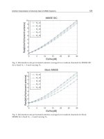
was found that the coatings with higher values of SR demonstrated lower surface temperatures. A strong correlation (R2 = 0.92) was
found between the maximum daily surface temperature and the SR of the samples. We can therefore assume that the main factor
affecting the thermal performance of the samples during the day is their SR.
During the night when there is no solar radiation, the surface temperature of the samples was found to be quite uniform due to
the fact that all the coatings have an emissivity of about 0.88. However, cool-colored coatings remain cooler (by 0.1–1.6 °C) than
the standard color-matched coatings, probably because they have absorbed smaller amounts of solar radiation during the day.
Small variations in the measured emissivity explain the variations in the night surface temperature.
646
3.19.2.2
Applications
Use of Phase Change Materials to Enhance the Performance of Cool-Colored Coatings
Phase change materials (PCMs) may store heat in their mass under the form of latent heat. PCMs are widely used in solar
applications as well as in building materials, like plaster, to absorb the excess heat in buildings. Microencapsulated PCMs are
commercially developed and are available at a particle size ranging between 17 and 20 μm. Microparticles include a phase change
ingredient, usually paraffins, in their core and a polymer or a plastic in the exterior shell. The melting temperature may vary
according to the specific needs.
Phase change microparticles have been used to further enhance the performance of cool color coatings. They have been used to
develop coatings based on infrared reflective pigments doped with PCMs [33]. Six different colored pigments have been tested while
investigations have been performed regarding the melting temperature of the microcapsules and the weight percentage of the
materials. The PCM-doped coatings as well as the conventional infrared reflective and the common coatings have been used to paint
concrete tiles, and their surface temperature has been measured during the summer of 2008 (Figure 13). Surface temperature
sensors and infrared thermography techniques have been used.
Measurements have shown that the PCM-doped materials present a peak daily temperature of up to 4 °C lower compared to
conventional infrared reflective coatings and up to 9 °C compared to common coatings.
Figure 14 shows the daily variation of the surface temperature of black tiles, coated with PCM-doped, conventional infrared
reflective, and common black coatings, for 10 consecutive days of measurements. As shown, during the whole measurement period,
the peak surface temperature of PCM-doped coatings was in all cases 2–4 °C lower than that of the conventional infrared reflective
Figure 13 Picture of the tested cool phase change coatings.
75
Common
Cool
PCM
Temperature (°C)
65
55
45
35
25
15
1
2
3
4
5
6
7
8
9
10
Period of measurements (days)
Figure 14 Daily variation of the surface temperature of black tiles coated with phase change material (PCM)-doped, conventional infrared reflective, and
common black coatings.
Passive Solar Architecture
647
78
TCOOL
68
Temperature (°C)
58
48
38
28
18
ΔT(COOL–PCM)
8
–2
1
2
3
4
5
6
7
8
9
10
Period
Period of
of measurements
measurements (days)
(days)
Figure 15 Daily variation of the surface temperature difference between the phase change material (PCM)-doped and the conventional infrared reflective
coatings. Also, the daily variation of the conventional infrared reflective material is shown.
coatings. During the night period, both the PCM-doped and the conventional infrared reflective coatings presented substantially
lower surface temperatures than the common black paints.
The measured temperature difference between the PCM-doped and the conventional infrared reflective coatings varies during the
day, presenting its maximum during the morning hours when the surface temperature approaches the melting point of the PCM.
Figure 15 shows the daily variation of the surface temperature difference between the PCM-doped and the conventional infrared
reflective coatings together with the daily variation of the temperature of the conventional infrared reflective material. As shown, the
maximum temperature difference between the two coatings is seen at about 9.30 a.m. when the temperature of the material reaches
the fusion temperature of the PCM. At that time, the temperature difference between the two materials varies between 8 and 10 °C.
Figure 16 shows the daily variation of both the PCM-doped and the conventional infrared reflective materials. During the night
period, both materials present a similar temperature. At about 8.00 a.m., the PCM starts to melt and the surface temperature of this
coating presents a much lower increase than that of the conventional one, until 9.30 a.m., when the maximum surface temperature
difference is achieved. At that time, convective phenomena between the tiles and the ambient air are much more intensive for the
PCM-doped coating as its surface temperature is considerably lower. Thus, the rate of increase of the surface temperature of the
PCM-doped material starts to be much higher than that of the conventional coating and this continues until the early afternoon period
when surface temperatures reach their maximum. In the afternoon period, the rate of decrease of the surface temperature of the
67
Common
Cool
PCM 24 C
57
Temperature (�C)
PCM 28 C
47
37
27
17
1
2
3
Period of measurement (days)
Figure 16 Daily variation of the surface temperature of the common, conventional infrared reflective, and phase change material (PCM) 28 ° C and PCM
24 ° C doped infrared reflective black coatings.
648
Applications
PCM-doped material is quite lower until the sunset when both materials present almost a similar temperature. During the night
period, latent heat released by the PCM-doped material does not have any significant impact on the surface temperature of the coating.
3.19.2.3
Development of Thermochromic Coatings
Highly reflective materials contribute substantially to decrease the cooling load of buildings; however, they may also increase
the heating needs during the winter period. The development of coatings that respond thermally to the environment and may
change reversibly their color could present high advantages. Materials that may present high absorptance during winter and
high reflectance during summer could contribute to decrease both the heating and cooling needs of buildings.
Thermochromic coatings present a thermally reversible transformation of their molecular structure that causes a spectral
change of visible color [34–36].
Thermochromic materials are based on organic leuco dye mixtures composed of three main components:
1. a solvent, which usually is an alcohol or an ester, the melting point of which defines the transition temperature at which the
coating changes its color;
2. a color former, which usually is a cyclic ester that defines the color of the coating in its colored state; and
3. a color developer, which is a weak acid responsible for the color intensity of the product.
To protect the thermochromic system from the chemicals used in a coating and to prevent aging and oxidation, the mixture is
encapsulated in microspheres of less than 15 μm [35–44]. However, aging is a major problem for thermochromic materials as
absorption of ultraviolet (UV) energy can cause the breaking and/or cross-linking of the polymer chains, leading to altered chemical
and mechanical properties [45].
Thermochromic coatings for the outdoor environment have been developed and tested by Ma et al. [46, 47]. It has been found
that for temperatures above the transition temperature of the thermochromic system, its surface temperature was 4 °C lower than
that of the ordinary colored coating. Karlessi et al. [33] have developed and tested thermochromic coatings for buildings and urban
structures. The color transition temperature of the coatings was 30 °C. Microencapsulated pigments having a particle size close to
5 μm have been used while the slurry form contained almost 50% of solid thermochromic compound. Two types of coatings have
been prepared and tested: the first comprised only the thermochromic pigments and the binder, while in the second, titanium
dioxide (TiO2) has been added to avoid transparency of the coating at the warm state. Coatings of six different colors with and
without TiO2 have been developed and tested.
Measurements of the spectral reflectance of all the prepared coatings, shown in Figure 17, in both the colored and colorless state,
have shown that in the visible range of the colored state, the thermochromic coatings present almost similar reflectance with the
cool and common coatings. In parallel, all thermochromic coatings presented a very high reflection in the NIR and a very strong
absorption in the near UV. Comparison between the reflectance curves of thermochromic coatings at their colored phase and their
colorless phase shows that thermochromic coatings can absorb solar energy at lower temperatures and reduce the absorption at
higher temperatures. The SR of each developed thermochromic coating, shown in Table 3, is higher in both the colored and
colorless phases than the cool and common coatings. In particular, green thermochromic coating with TiO2 presents an increase of
its SR at the white phase by 43%, while for the yellow coating the increase was only of 4%. The infrared emittance of all
thermochromic coatings range from 0.83 to 0.91 and no significant differences are observed against the cool and common coatings.
Comparative testing of the surface temperature of the developed thermochromic coatings against common and cool coatings has
shown that thermochromic materials present much lower surface temperatures, as shown in Figure 18. A detailed comparison of the
measured mean and maximum daily surface temperatures as well as of the mean nocturnal temperatures for the thermochromic as well
as for the cool and common coatings is given in Tables 4–6. As shown, temperature differences range from 2.2 °C for thermochromic
and cool yellow to 9.2 °C for thermochromic and cool brown and from 4.2 °C for thermochromic and common yellow to 11.4 °C
for thermochromic and common green. In parallel, thermochromic coatings demonstrate 10–15 °C lower mean maximum daily
temperatures than cool coatings, and 18–20 °C lower than common coatings. For yellow coatings, the ΔTmax(cool-thermo) was close to
1.5 °C, and ΔTmax(common-thermo) was 6.8 °C. Also, for blue coatings, the ΔTmax(common-thermo) was equal to 10.1 °C. Nocturnal
temperature differences between thermochromic, cool, and common coatings are not found to be significant. Figure 19 shows the
mean surface temperature profile of all the green coatings for August.
By applying statistical methods, it is found that the mean surface temperatures of both groups of thermochromic coatings (with
TiO2 and without TiO2) are significantly different from that of the cool and common coatings, at a significant level of 0.05.
Aging tests have been performed and various techniques have been tested to decrease the degradation of the thermochromic
coatings. Although an important improvement has been achieved, further research to stabilize the optimal properties of the
materials is necessary.
3.19.2.4
Development and Testing of Colored Thin-Film Layers of Asphalt
The reflectivity of asphalt may be increased and its surface temperature can be reduced significantly when colors are mixed with
binder or lighter colored aggregates are used. Also, chip seals and emulsions of lighter colors can be used to increase the reflectivity
of the asphaltic products.
Passive Solar Architecture
Thermo-colored phase
Thermo-white phase
100
Thermo-colored phase
Thermo-white phase
Common
Cool
UV
VIS
GREEN + TiO2
NIR
Reflectance (%)
Reflectance (%)
80
60
40
20
Cool
UV VIS
GREEN + TiO2
NIR
60
40
20
0
300
800
1300
1800
0
300
2300
800
Wavelength (nm)
Thermo-colored phase
Thermo-white phase
UV VIS
1300
1800
2300
Wavelength (nm)
Common
Thermo-colored phase
Thermo-white phase
Cool
GRAY + TiO2
NIR
Common
Cool
100
100
UV
VIS
GRAY + TiO2
NIR
80
Reflectance (%)
80
Reflectance (%)
Common
100
80
60
40
60
40
20
20
0
300
800
1300
1800
2300
0
300
Thermo-colored phase
Thermo-white phase
UV
VIS
800
1300
1800
2300
Wavelength (nm)
Wavelength (nm)
100
649
Common
Cool
NIR
BROWN+TiO 2
Reflectance (%)
80
60
40
20
0
300
800
1300
1800
2300
Wavelength (nm)
Figure 17 Spectral reflectance of thermochromic, cool, and common coatings of the same color.
Twenty-six asphalt pavements composed of different aggregates and of five different colors (whitish, green, red, yellow, and
natural) have been developed and tested to investigate their heat-island mitigation potential [48]. As shown in Figure 20, the
reflectivity of the developed asphalt pavements is much higher than that of the common asphalt. In particular, colored asphalt
materials present a reflectivity in the visible range between 20% and 70%, while the corresponding reflectivity of common asphalt is
not higher than 4%. In parallel, in the infrared spectrum, the reflectivity of the colored asphalt products varies between 40% and
55%, while the conventional material presents a reflectivity close to 6%. The measured reflectivity of representative colored asphalt
materials in the UV, visible, and infrared parts is given in Table 7. The total SR of the colored asphalt materials varies between 27%
and 55%, while the corresponding value for the conventional black asphalt is 4%.
All developed colored asphalt materials have been exposed to the outdoor environment during the summer of 2008 and their
surface temperature has been measured for about a month. The maximum daily temperature of representative colored and black
asphalt materials is given in Figure 21. As shown, colored asphalt products present a reduction of the maximum daily temperature,
which ranges between 5.6 and 16.5 °C. The daily variation of the surface temperature of representative colored and black asphalt
materials is given in Figure 22.
The use of colored asphalt materials may reduce the surface temperatures in the urban environment and contribute highly to
mitigate heat island in cities.
650
Table 3
Applications
SR and % increase in the SR of thermochromic, cool, and common coatings
SR
(%)
Green
Yellow
Brown
Black
Blue
Gray
With TiO2
Without TiO2
With TiO2
Without TiO2
With TiO2
With TiO2
Without TiO2
With TiO2
Without TiO2
With TiO2
Without TiO2
Thermochromic
% Increase
% Increase
% Increase
Colored
phase
Colorless
phase
SR (colorless-colored)
Cool
SR (thermocolored-cool)
Common
SR (thermocolored-common)
51
33
78
70
55
40
40
59
41
55
34
73
45
81
73
76
53
47
71
54
73
40
43
36
4
4
38
33
18
20
32
33
18
41
27
73
69
41
17
12
53
32
44
25
24
22
7
1
34
135
233
11
28
25
36
18
4
64
64
18
3
3
51
21
13
13
183
725
22
9
206
1233
1233
16
95
323
162
SR, solar reflectance.
(a)
(b)
Thermochromic
60.0 °C
Cool
50
40
Common
30
AR01
28.4 °C
(c)
(d)
65.7 °C
60
Cool
50
Thermochromic
40
Common
30
20
19.9 °C
Figure 18 Visible (a), (c) and infrared (b), (d) images of blue with TiO2 and black without TiO2 thermochromic, cool, and common coatings, respectively.
Table 4
Mean daily surface temperatures (°C) for thermochromic, cool, and common
coatings in August
Mean daily surface temperature (°C) in August
Thermochromic
Green
Yellow
Brown
Black
Blue
Gray
Cool
Common
With TiO2
Without TiO2
With TiO2
Without TiO2
Light
Dark
33.2
32.2
31.0
37.6
33.1
34.1
36.0
32.5
40.9
34.4
40.2
44.6
38.7
40.4
43.8
35.3
44.6
36.4
42.3
48.5
38.4
37.4
35.5
45.2
42.4
44.4
39.0
45.1
47.5
43.9
Passive Solar Architecture
651
Table 5
Mean maximum daily surface temperatures (°C) for thermochromic, cool, and
common coatings in August
Mean maximum daily surface temperature (°C) in August
Thermochromic
Green
Yellow
Brown
Black
Blue
Gray
Cool
Common
With TiO2
Without TiO2
With TiO2
Without TiO2
Light
Dark
44.2
42.5
40.2
50.3
42.7
44.3
49.5
43.8
57.0
44.0
54.9
63.8
52.3
56.1
61.1
46.7
63.6
49.3
59.2
69.8
51.5
49.6
46.7
64.4
59.2
63.0
52.8
64.3
68.0
62.6
Table 6
Mean nocturnal surface temperatures (°C) for thermochromic, cool, and common
coatings in August
Mean nocturnal surface temperature (°C) in August
Thermochromic
Green
Yellow
Brown
Black
Blue
Gray
3.19.2.5
Cool
Common
With TiO2
Without TiO2
With TiO2
Without TiO2
Light
Dark
18.0
18.5
18.6
21.3
20.0
21.0
17.8
18.0
20.2
17.6
21.0
20.4
20.7
20.2
21.6
20.5
20.2
20.2
20.6
20.7
21.1
20.6
20.5
20.6
20.5
20.8
20.9
20.3
21.1
20.2
Green Spaces for Urban Buildings
The importance of green spaces to mitigate urban heat island has been stressed by many researchers. Trees create a favorable
thermal balance for humans and enhance outdoor thermal comfort [49]. Papadakis et al. [29] have conducted measurements to
investigate the ability of trees to control solar radiation on vertical facades in Greece. It is reported that almost 70–85% of the
incident radiation was intercepted by the trees while the ambient temperature behind the shaded area was relatively lower than
those without the trees.
Building-integrated green spaces are mainly green rooftops. A typical green roof consists of a soil mixture and a drainage layer
(see Figure 23). Green roofs can be categorized as intensive and extensive, depending upon the use, the depth of plantation, and the
required maintenance. Intensive green roofs are usually traditional roof gardens that require a relatively thick soil to grow large
plants and they require increased irrigation, feeding, and other maintenance. They are normally accessible as a recreation space for
residents and so incorporate areas of paving, seating, and other architectural features. In contrast, extensive green roofs feature a
lightweight growing medium and self-generative plants. They are designed to be self-sustaining and require only a minimum of
maintenance, perhaps a once-yearly weeding or an application of slow-release fertilizer to boost growth. Extensive roofs are usually
only accessed for maintenance.
Planted roofs can contribute highly to mitigate heat island. Planted roofs present much lower temperatures than hard surfaces
and contribute to decrease the ambient temperature through convection and evapotranspiration.
Eumorfopoulou and Aravantinos have simulated various planted roof elements with different heights of plants and different
drainage and they have performed comparisons between a bare roof and a planted roof. It is concluded that the planted roof
contributes highly to the thermal protection of buildings but cannot replace the thermal insulation layer [50].
Niachou et al. have reported extensive measurements of a planted roof in Greece and they concluded that it contributes to reduce
seriously the cooling load of buildings. The application of the green roof reduced the percentage of maximum indoor air
temperature exceeding 30 °C to 15% from 68% without the green rooftop. The energy efficiency due to green roofs for a
noninsulated building was 37–48%, while for an insulated building it was quite low (5%) [22].
The benefits of an intensive rooftop garden installation in a tropical environment were investigated by Wong et al. through field
measurements carried out in Singapore. The analysis reveals that the temperature measured under the vegetation depends upon the
plants’ leaf area index. Lower temperatures were measured under vegetation with increased leaf area index. The cooling effect of
plants was also confirmed by the ambient air temperature reduction observed at different heights. A maximum temperature
difference of 4.2 °C was obtained between the locations with and without the plants [51].
652
Applications
(a)
Common
Cool
Tamb
Thermochromic
80
with TiO2
Temperature (°C)
70
60
50
40
30
20
10
0
0:00
4:48
9:36
14:24
19:12
0:00
Time (hh:mm)
(b)
Common
Cool
Tamb
Thermochromic
80
without TiO2
70
Temperature (°C)
60
50
40
30
20
10
0
0:00
4:48
9:36
14:24
19:12
0:00
Time (hh:mm)
Figure 19 Mean daily surface temperature profile of ambient temperature (Tamb) and of green-colored thermochromic, cool, and common coatings with
TiO2 (a) and without TiO2 (b) in August.
80
Reflectivity SR (%)
Whitish
60
Yellow
Black
40
Green
20
Natural
0
300
Red
800
1300
1800
2300
Wave Length (nm)
Figure 20 Spectral reflectance of various colored asphalt surfaces and of the conventional black asphalt.
Wong et al. also carried out energy simulations to estimate the energy savings for a commercial building in Singapore with an
intensive green roof. The annual energy savings were estimated to be around 15%. Increase of soil thickness contributes to the
increase of energy savings and more than 60% of heat gain was intercepted by the rooftop system [52].
It is therefore more than obvious that green spaces and green rooftops constitute a feasible mitigation strategy for urban heat
island leading to a substantial decrease in energy consumption.
Passive Solar Architecture
Table 7
materials
653
Measured reflectivity of colored and conventional asphalt
Product
SR
(%)
SRUV
(%)
SRVIS
(%)
SRNIR
(%)
Whitish
Yellow
Green
Black conventional
Natural
Red
55
40
27
4
45
27
10
8
8
4
10
6
45
26
10
3
31
10
63
51
39
4
56
40
Maximum daily surface temperature (°C)
SR, solar reflectance; SRNIR, solar reflectance in the near-infrared region; SRUV, solar
reflectance in the ultraviolet region; SRVIS, solar reflectance in the visible region.
80
70
ΔT = 16.5
60
ΔT = 11.2
ΔT = 11.7
Natural
Yellow
ΔT = 6.3
ΔT = 5.6
Green
Red
50
40
30
20
10
0
Black
Whitish
Figure 21 Maximum daily surface temperature of colored and conventional black asphalt pavements.
Black
Whitish
Natural
Yellow
Green
Red
80
Surface temperature (°C)
70
60
50
40
30
20
10
0
0:00
4:48
9:36
14:24
19:12
0:00
Time (hh : mm)
Figure 22 Daily variation of the surface temperature of representative colored and black asphalt materials.
3.19.2.6
Discussion
The mitigation of the heat-island effect can be achieved by decreasing the thermal gains in the urban environment, and in particular,
the amount of the absorbed solar radiation. This can be done by increasing the albedo of cities using materials for buildings and the
urban fabric that have high SR values. In order to meet the building market’s aesthetic preferences, cool nonwhite materials are
needed. The results of the relevant research indicate significant success in developing cool-colored coatings doped or not with PCM
microcapsules, thermochromic materials, and cool asphalt coatings that have the same visible reflectance as the standard coatings,
654
Applications
Vegetation layer
Growing media (soil)
Drainage layer
Protection layers
Figure 23 A green roof structure [17].
appearing to have the same color, but for the colored coatings they exhibit a more selective absorption band in the infrared part of
the spectrum, reflecting large parts of the solar energy that arrives as infrared radiation rather than absorbing it. This results in lower
surface temperatures for all the coatings.
The use of cool coatings is not limited to their direct application on building envelopes, resulting in the reduction of surface
temperatures and leading to lower cooling energy consumption for air-conditioned buildings and increased thermal comfort for
unconditioned building; they can also be used to manufacture other cool building and paving materials. The use of cool coatings is
a passive solution that combines energy efficiency and the aesthetic appeal of the products.
Therefore, solar architecture techniques in the building fabric that can contribute simultaneously to the mitigation of the urban
heat island and to the reduction of the energy consumption are as follows:
• Improvement of the urban microclimate and increased vegetation – urban greening. Many studies have been carried out on
the cooling benefits of trees and vegetation within the cities. Surface peak temperature reductions of up to 20 °C may be
possible on hot, sunny days. Vegetation augmentation and reduction of impervious surface cover in urban environments can
be accomplished through residential and municipal tree planting programs, addition or expansion of ecoroofs (or green
roofs), and implementation of pervious pavements. While many studies focus on the evapotranspiration benefits of urban
trees, it is important to note that trees also affect wind patterns within cities. Thus, by changing wind patterns, trees may
alter the effectiveness of cooling breezes and can play an important role in dispersion processes as well as pollutant removal
by deposition.
• Increase of surface albedo by the use of cool materials and coatings. The primary surfaces in the urban environment that are
amenable to albedo increase are rooftops. In order to assess potential for albedo modification, various studies have estimated the
composition of the urban fabric. This composition varies for different land use subtypes within a city and depends on whether
one is concerned with the plan view data (as seen from a plane) or with the actual composition under the canopy. With respect to
the plan view composition of cities, these studies typically find that roughly 20% of a city’s surface is rooftop. 30% is pavement,
and the remainder is a combination of vegetation canopy and other surfaces. It is this underlying composition that limits the
potential effectiveness of any albedo-related mitigation strategy.
3.19.3 Control Systems for Solar Architecture
The main challenge in the design of control systems for energy performance of buildings is to find the balance between
implementation costs, operation costs, energy consumption, indoor climate quality, users’ satisfaction, and contribution to
sustainable building. Intelligently designed buildings are those that involve environmentally responsive design, taking into account
the surroundings and building usage and involving the selection of appropriate building services and control systems to further
enhance building operation with a view to the reduction of energy consumption and environmental impact over its lifetime. This
procedure requires advanced control techniques to establish a balance among the following (see Figure 24):
•
•
•
•
•
user comfort requirements,
energy consumption,
passive solar design concepts,
solar heating and cooling technologies, and
PV.
Passive Solar Architecture
Earth cooling
Visual comfort
Radiative cooling
Indoor air quality
Evaporative
cooling
Thermal comfort
655
Shading control
Daylighting
control
Passive
solar
design
Solar heating
Window
control
Solar
systems
Solar cooling
Photovoltaics
Energy and
power meters
Figure 24 The advanced control systems in solar buildings.
Various control strategies are used for the regulation of the above. The combined control of active and passive systems, as,
for example, night ventilation for cooling and mechanical cooling or hybrid ventilation, generally requires the use of the
so-called ‘logic control’ implemented by various rules in order to determine which of the passive or active systems should be
operated.
Many digital controllers offer this possibility to implement logic control rules as well as ON–OFF or proportional–integral–
derivative (PID) control [53, 54]. Modern control systems provide optimized operation of the energy systems while satisfying
indoor comfort. Recent technological developments based on artificial intelligence techniques offer several advantages compared
with the classical control systems. The use of fuzzy logic and artificial neural networks (ANNs) in various building-related
applications has been growing significantly over the years [55–62]. The results have revealed the potential usefulness of the
advanced control strategies for the energy management of houses and buildings. Evolutionary computing techniques, namely,
genetic algorithms (GAs), are employed in buildings since they have proved to be robust and efficient in finding near-optimal
solutions in complex problem spaces [63, 64]. Predictive control techniques are also applied [65].
Finally, optimization methods such as dynamic programming [66], multiobjective techniques [67], and simulation-assisted
multicriteria analysis [68] are widely adopted due to buildings’ nonlinearity.
3.19.3.1
Controlled Parameters and Control Variables in Passive Solar Architecture
Passive solar architecture cannot be implemented without taking into account the various controlled parameters that the overall
system will regulate. The most widely used in the literature concern occupants’ thermal, visual, and acoustic comfort as well as the
IAQ. The building’s occupants have a direct impact on the passive design operation and the effectiveness of passive solar
architecture. For example, the influence of occupants’ behavior on the energy consumption is studied by Foster et al. [69]. In this
chapter, the interaction between the occupants and the venetian blinds is examined as blinds are the key element in the passive
control of glare, daylighting, and overheating, all of which affect both the occupants’ comfort and the energy consumption.
The American Society of Heating, Refrigerating and Air-Conditioning Engineers (ASHRAE) Standard 55 describes thermal comfort
as ‘the condition of mind which expresses satisfaction with the thermal environment’. The environmental variables that influence
thermal comfort are the air temperature, the mean radiant temperature, the air velocity, and the water vapor pressure in ambient air.
Two other important variables are the person’s activity level and clothing. Most of the above are combined in the predicted mean vote
656
Applications
(PMV), which provides information on the degree of discomfort experienced in a thermal environment with an extra invocator, the
percentage of people dissatisfied (PPD) [70, 71]. Regarding thermal comfort, the controlled parameters found in the literature involve
•
•
•
•
•
PMV [72–74],
the PPD [75],
indoor temperature [76],
maximum daily discomfort in degree hours [77], and
zone operative temperature [75].
Regarding visual comfort, the control involves passive shading targeting the regulation of workplane illuminance [65, 78].
Additionally, the daylight glare index regulated through the adjustment of shading and electric lighting is proposed as the controlled
variable for visual comfort [79].
Regarding the solar system operation, the following controlled parameters are found:
• tank water temperature for solar collectors for the simultaneous control of indoor environment and water circuit [76] and
• supply and return temperature of passive solar systems’ collector [75].
In terms of energy consumption, the controlled variables may be
• seasonal building load profiles [77],
• buildings’ heating or cooling balance points (i.e., the temperature above or below which cooling or heating is necessary) [77], and
• building load coefficient [67].
Other parameters that are taken into account in the formulation of the control strategy include
• climatic conditions either measured or predicted [80] and
• presence of detectors.
The control variables differ according to the passive system. The most representative are the following [74, 76, 81]:
•
•
•
•
•
•
•
•
heating, ventilating, and air conditioning (HVAC) ON–OFF,
boilers or chillers,
coils and valves,
water pumps,
supply and exhaust fans,
electric lighting control,
shading control, and
window motors.
All the above environmental parameters and control variables are integrated into the various control strategies described in the
next section targeting to minimize the energy consumption and create a comfortable and qualitative environment for the
building users.
3.19.3.2
Control Strategies in Solar Architecture
The control theory for linear systems has been considered for quite a long time as a well-established scientific discipline with
different techniques for analyzing and designing controllers.
The main problems in applying the linear control theory for solar architecture are caused by the fact that (1) linear mathematical
models are needed and cannot be straightforwardly extracted, (2) the developed mathematical models of such complicated
processes cannot take into account all aspects of reality and therefore simplifications and assumptions are necessary, (3) most
processes for solar architecture techniques are not linear, and (4) due to continuous changes of the climatic conditions, solar system
processes vary dynamically with time.
The control techniques used for solar architecture can be divided into different categories (tabulated in Table 8) [82, 83], and
these are explained below.
3.19.3.2.1
Conventional control for solar architecture
Conventional control strategies for solar architecture include the widely used ON–OFF and conventional PID methods [84]. The
conventional control strategies are still very attractive when they involve a small number of environmental parameters’ regulation
and a limited number of solar techniques. For example, active ON–OFF control is proposed by Tzempelikos and Athienitis [78] for
the regulation of electric lighting consumption in a simulation-based thermal and daylight analysis for office spaces. The ON–OFF
system is based on occupancy sensors, while the buildings are designed to exploit the daylight availability via window sizing,
orientation, and window-to-wall ratio.
Passive Solar Architecture
Set points
+
657
e(k)
–
PI
u(pi)
e(k–1)
z –1
+
Actuators (k)
+
+
Building
+
y(k)
–
D
+
z–1
u(d )
Figure 25 The proportional–integral–derivative control diagram.
Due to the dynamic characteristics of the technologies involved in the solar architecture, it is quite difficult to obtain a satisfactory
performance when an integrated approach is established where a combination of passive heating and cooling techniques is
considered. The use of PID controllers (Figure 25) with fixed gains KP, KI, KD although applied in numerous cases [85] cannot
deal with nominal operation of the various components without including a feedforward term in the control loop to account for the
effect of the quite significant disturbances and time variations. Gain scheduling proportional–integral (PI) controllers, adaptive PID
controllers, and fuzzy logic- or neural network (NN)-based PID controllers are some examples of PID feedforward actions and
adaptations to buildings’ dynamic characteristics [86].
Classical PID as well as ON–OFF control has been proved to be energy ‘inefficient’ due to the fact that the controlled variable
creates overshootings and oscillations once the reference signal is reached [85]. Overshootings and oscillations are the main cause of
energy waste.
3.19.3.2.2
Advanced control
Based on the categorization in Table 8, advanced control for solar architecture includes model-based predictive control and adaptive
control. Predictive control in solar architecture uses a model to estimate and predict the optimum control strategy to be
implemented (Figure 26).
While the online control systems can react only to the actual building conditions, a model-based predictive control can move
forward in time to predict the buildings’ reaction to alternative control schemes. Therefore, different control scenarios can be
evaluated based on suitable objective functions and create a control state space that corresponds to a building’s performance space.
A model can be either a ‘black box’ or a ‘physical’ model. In the ‘black box’ or nonphysical model approaches, self-learning
algorithms, reinforced learning [87], or NNs [88] are some of the methodologies found in the literature. The benefits of the
mentioned approaches are low computational time and the fact that they do not require any specific building modeling expertise,
while their limitations are that, on the one hand, NNs require reliable training data that may not be available and, on the other
hand, self-learning algorithms cannot move beyond the limits of their experience. When physical models are utilized, the expert has
the opportunity to understand the cause-and-effect relationship between the various building components, the control strategies,
and the climatic conditions. The physical models approach can use stochastic mathematical models [89] or simulation-assisted
predictive control [90]. Some physical models, though, require high computational skills and effort. For this reason, integration of
Table 8
Control strategies for solar architecture
Control category
Control strategies
Conventional control
ON–OFF
Proportional–integral–derivative control
Feedforward control
Model-based predictive control
Adaptive control
Optimal control
Fuzzy logic
Neural network
Advanced control
Intelligent techniques
658
Applications
Model
ym (k)
Adaptation
techniques
x3
Controller
u(k)
Building
y(k)
Figure 26 Model-based predictive control.
whole-building thermal models with (cognitive-based) control is quite interesting and with significant potential – see References 91
and 92 for some efforts.
Adaptive control has been developed for decades, and now it has become a rigorous and mature discipline which mainly focuses
on dealing with uncertainties in control systems. Since adaptive control usually involves adaptive estimation algorithms, it can deal
with relatively large uncertainties and gain flexibility to fit the unknown system, therefore playing a role of ‘learning’ in some sense.
The adaptive control systems in solar buildings are used to modify the controller dynamically during its operation, that is,
adjusting the controller to building users’ preferences, modifying the control actions so as to fit to specific operational, usually
predefined, performance (Figure 27).
Therefore, the main advantage of adaptive control comes from the fact that adaptive controllers can adjust themselves
to modify the control law based on estimation of unknown parameters by identification algorithms. Consequently, the adaptive
control field is very closely connected to the systems’ (in our case, building components) identification algorithms, in which
an area is aiming at providing and investigating mathematical tools and algorithms that build dynamical models from
measured data.
Typically, in system identification, a certain model structure which contains some unknown parameters is selected by the user
and then by the use of some recursive algorithms which are based on specific model characteristics, statistical data, and noise, these
unknown parameters are extracted. The methods or algorithms developed in system identification are borrowed in adaptive control
in order to estimate the unknown parameters in the closed loop. For convenience, the parameter estimation methods or algorithms
adopted in adaptive control are often referred to as adaptive estimation methods. Adaptive estimation and system identification
share many similar characteristics; for example, both of them originate and benefit from the development of statistics. One typical
example is the least-squares algorithm that is applied to system identification, statistics, or adaptive control and gives parameter
estimation by minimizing the sum of squared errors.
As an example of the above, a bilinear model-based predictive control is proposed by Kolokotsa et al. [65], so as to achieve
optimum indoor environmental conditions while minimizing energy costs by the prioritization of natural ventilation for cooling,
shading regulation for optimum daylight utilization, and window operation for a building energy management system. The control
diagram depicted in Figure 28 includes the actuators (A) and the overall installation (P), where k is the sample time, x(k) the state
vector, y(k) the measurements vector, n(k) the unknown noise for the measurements, u(k) the control vector, d(k) the disturbances
vector (casual gains, door opening, people smoking, etc.), and xs the set point vector.
Bilinear models are developed for the thermal comfort, visual comfort, and IAQ where the indoor temperature, relative
humidity, indoor carbon dioxide concentration, and indoor illuminance behavior are modeled. The least-squares estimation is
Adaptation/
identifier
xs
Figure 27 Self-tuning controller.
+
– e(k)
Controller
Building
y(k)
Passive Solar Architecture
659
d(k)
Xs
y(k)
Controller
u(k)
A
P
x(k + 1)
Δ–1
x(k)
n(k)
x(k)
y(k)
f (x(k),u(k),d(k))
Figure 28 Model-based predictive control for indoor comfort and energy efficiency regulation [65].
performed separately for each actuator that influences the corresponding environmental parameter by putting the building energy
management systems (BEMS) in continuous operation mode for at least 48 h.
Following the identification procedure, the BEMS controller is designed to minimize the performance index J(k) which aims to
keep the environmental variables as close as possible to the defined set points xs and simultaneously minimize the energy
consumption. J(k) is defined as
JðkÞ ¼ ‖xin ðk þ 1Þ − xs ‖Q þ ‖uðkÞ‖R
2
2
½1
where Q and R are weight matrices corresponding to the set points’ proximity and the actuators’ electric energy cost, respectively. The
bilinear model-based predictive control’s response to fluctuations in the environmental variables is found to be fast and stable.
Finally, the controller’s performance is tested by an installation in specific building where comfort, weather data, and prediction
model are integrated into a common architecture (Figure 29); the controller’s performance is found to be quite satisfactory and
selects the optimum solutions based on the energy consumption and the set point proximity by satisfying the performance index J
(Figure 30).
3.19.3.2.3
Intelligent systems
Recent research in building-related artificial intelligence topics has shown that artificial intelligence techniques such as fuzzy
systems and NNs can contribute to a significant reduction of energy consumption while maintaining indoor comfort in acceptable
margins by regulating the operation of the various building-integrated solar systems or by giving priority to passive means in order
to cover the comfort or energy requirements.
Fuzzy logic (Figure 31) is based on the way the human brain deals with inexact information. Fuzzy systems are structured
numerical estimators. They start from formalized insights about the structure of categories that exist in the real world and then
formulate the fuzzy IF–THEN rules that represent expert knowledge. They combine fuzzy sets with fuzzy rules and they produce
complex nonlinear behavior. Fuzziness is often confused with probability. The main difference between fuzzy logic and probability
is that fuzziness deals with deterministic plausibility while probability concerns the likelihood of nondeterministic and stochastic
events. Fuzziness expresses the uncertainty in the definition of phenomena such as ‘tall person’ and ‘large room’. The major feature
of fuzzy logic is its ability to express the ambiguity in human thinking, subjectivity, and knowledge in a comparatively accurate
manner.
As a result of the above, the use of fuzziness in buildings’ solar architecture systems and components is applicable for the
following reasons:
• A fuzzy description of the operational characteristics under study fits naturally to the problem.
• The systems to be controlled are usually nonlinear.
ANNs imitate the operation of the human brain’s neurons. They are composed of a number of elements/neurons operating in
parallel and are inspired by the biological nervous systems. A schematic diagram of typical multilayer feedforward ANN architecture
is shown in Figure 32. The network as depicted in Figure 32 usually consists of an input layer, the hidden layers, and an output
layer. The number of hidden layers depends on the complexity of the problem under study. Each neuron is connected to other
neurons of a previous layer through adaptable synaptic weights. Usually, the biggest challenge faced when designing an NN is to
find the right number of neurons in the hidden layer. This depends on the number of inputs and outputs and also on the number of
training cases.
The GAs are adaptive search and optimization algorithms that work by mimicking the principles of natural genetics. GAs are
very different from traditional search and optimization methods used in engineering design problems [93]. Fundamental ideas
of genetics are borrowed and used artificially to construct search algorithms that are robust and require minimal problem
information.
PC
RS 485
to
RS 232
RS 232
RS 485
Energy meter
electrex kilo
Indoor
humidity
sensor
QFA2000
Outdoor
humidity
sensor
QFA3160
Universal
I/O
module
5WG1 670-1AB03
EIB
power
supply
5WG1 125-1AB21
RS 232
interface
5WG1 148-1AB04
Indoor
Co2
sensor
QPA63.2
Energy and
power
meter
5KT1 165
Air-conditioning
Window
Universal
I/O
module
5WG1 670-1AB03
Shading
Shading
3-phase power supply
Shading
Motor
control
relay
5WG1 524-1AB01
Binary
outputs
5WG1 561-1AB01
Devices installed
at the rail
BUS
Power supply
24C DC
4a max.
Indoor
temperature
sensor
5WG1 256-4AB01
Indoor
brightness
sensor
5WG1 253-4AB01
Rain
detector
5WG1 258-3AB41
Weather
station
5WG1 257-3AB11
EIB-Gateway
DALI
5WG1 141-4AB01
Temperature
sensor
5WG1 258-3AB21
1
Brightness
sensor
5WG1 258-3AB31
Wind speed
sensor
5WG1 258-7AB12
Electronic
ballast
DALI
TRIDONIC
2/58 EXCELL
Lamb
Figure 29 The bilinear model-based predictive control BEMS architecture [65].
Lamb
2
Electronic
ballast
DALI
TRIDONIC
2/58 EXCELL
Lamb
Lamb
51
Electronic
ballast
DALI
TRIDONIC
2/58 EXCELL
Lamb
Lamb
AC 230 V
Passive Solar Architecture
661
100
90
80
70
60
50
Men
Women
40
30
20
10
0
Very good
Good
Bad
Very bad
Figure 30 Perception of indoor thermal comfort based on occupants’ responses [65].
e(k)
xs
+
–
Fuzzification
Fuzzy rules
Defuzzification
Δu(k)
Z–1
Z–1
y(k)
Building
u(k)
Figure 31 The fuzzy control system.
A typical unconstrained, single variable optimization problem can be outlined as follows:
maximize f ðxÞ
xmin ≤ x ≤ xmax
½2
The GA, as any evolution program, for a particular problem must have the following five components:
•
•
•
•
•
a generic representation for potential solutions to the problem;
a way to create an initial population of potential solutions;
an evaluation function that plays the role of the environment, rating solutions in terms of their ‘fitness’;
genetic operators (such as crossover and mutation) that alter the composition of children; and
applying genetic operators, and so on.
Indicatively, artificial intelligence in solar buildings control is found in the following applications:
• Lah et al. designed a fuzzy control system for the regulation of a movable shade roller blind, targeting the harmonization of
thermal and optical flows. They aimed to combine minimization of energy use with comfortable living and working conditions.
The control algorithm consisted of thermal and lighting parts, each one containing conventional and fuzzy controllers. The
impact on thermal light behavior was analyzed with adaptable window geometry. The controller is designed and adjusted so as to
adjust the inside daylight illumination level with moderate continuous movement of the roller blind. The overheating is reduced
by the roller blind regulation and the desired illuminance is reached [94].
• In the same route of the regulation of thermal and visual comfort is the work proposed by Kristl et al. [95]. A fuzzy controller for
the regulation of a roller blind is tested and tuned in an experimental chamber. A thermal comfort loop and an illumination loop
are developed and then these loops are merged to harmonize the results.