Volume 3 solar thermal systems components and applications 3 18 – concentrating solar power
Bạn đang xem bản rút gọn của tài liệu. Xem và tải ngay bản đầy đủ của tài liệu tại đây (11.64 MB, 42 trang )
3.18
Concentrating Solar Power
B Hoffschmidt, S Alexopoulos, C Rau, J Sattler, A Anthrakidis, C Boura, B O’Connor, and P Hilger, Aachen University
of Applied Sciences, Jülich, Germany
© 2012 Elsevier Ltd. All rights reserved.
3.18.1
3.18.2
3.18.2.1
3.18.2.2
3.18.2.3
3.18.2.4
3.18.2.4.1
3.18.2.4.2
3.18.2.4.3
3.18.2.4.4
3.18.2.4.5
3.18.2.4.6
3.18.2.4.7
3.18.3
3.18.3.1
3.18.3.1.1
3.18.3.1.2
3.18.3.1.3
3.18.3.1.4
3.18.3.2
3.18.3.2.1
3.18.3.2.2
3.18.4
3.18.4.1
3.18.4.1.1
3.18.4.1.2
3.18.4.1.3
3.18.4.1.4
3.18.4.1.5
3.18.4.1.6
3.18.4.1.7
3.18.4.2
3.18.4.3
3.18.5
3.18.5.1
3.18.5.1.1
3.18.5.1.2
3.18.5.1.3
3.18.5.1.4
3.18.5.1.5
3.18.5.1.6
3.18.5.1.7
3.18.5.1.8
3.18.5.1.9
3.18.5.1.10
3.18.5.1.11
3.18.5.2
3.18.5.2.1
3.18.5.2.2
3.18.5.2.3
3.18.5.2.4
3.18.5.2.5
3.18.5.2.6
Introduction
General Principles of Concentrating Systems
Concentration Effect
Energy and Mass Balance
Grid-Connected or Island Systems
Recooling
Closed-circuit recooling systems
Wet cooling systems
Mechanical draft cooling systems
Natural draft cooling towers
Hybrid cooling towers
Fan-assisted natural draft cooling towers
Air-driven condensers
Power Conversion Systems
Solar Only
Steam cycles
Organic Rankine cycles
Gas turbines
Solar dishes
Increase in Operational Hours
Hybridization
Storage
Cogeneration
Solar Cooling
Principles and technologies of solar cooling
Thermally driven cooling systems
Absorption chillers
Adsorption chillers
Best-practice examples for solar cooling
State of the art of solar cooling
Market expectations for solar cooling
Desalination
Off-Heat Usage
Examples
Commercial
SEGS
Andasol 1–3
PS10, PS20
STJ
Nevada Solar One
Sierra SunTower
Dish farm California
PE 1
AORA
Kimberlina solar thermal power plant
Others/under construction
Research
Solar One
Solar Two
CESA-1
DISS
STJ
SSPS
Comprehensive Renewable Energy, Volume 3
doi:10.1016/B978-0-08-087872-0.00319-X
596
596
596
597
597
597
597
597
598
598
599
600
600
600
600
600
603
604
605
605
605
609
611
611
612
612
612
613
613
614
614
614
615
615
615
615
616
617
619
620
620
622
622
622
623
623
624
624
625
626
626
627
627
595
596
Applications
3.18.5.2.7
3.18.5.3
3.18.5.3.1
3.18.5.3.2
3.18.6
3.18.7
3.18.7.1
3.18.7.2
3.18.7.3
3.18.8
3.18.8.1
3.18.8.2
3.18.8.3
3.18.8.4
References
Others
Studies
GAST
PHOEBUS
Economical Aspects
Environmental Aspects
Emission
Impact on Flora and Fauna
Life Cycle Assessment
Future Potential
Desertec
United States and Europe
MENA Region
Future Research Fields
627
629
629
629
629
630
630
630
630
631
631
631
634
634
634
3.18.1 Introduction
Solar thermal energy is a booming field worldwide. Many gigawatts of such energy are currently being built. There are different
competing technologies concerning the concentrator, heat transfer media, and power cycle.
Concentrating solar systems can be used for chemical reactions. Concentrated solar chemical applications include fuel produc
tion, for example, hydrogen, melting of metals which need high temperatures, and production of other chemical compounds.
The focus of this chapter is only the production of power and the use of the heat produced from concentrated solar thermal
power systems.
3.18.2 General Principles of Concentrating Systems
3.18.2.1
Concentration Effect
Theoretically, concentrating solar systems can reach considerably higher temperatures without reducing their thermal efficiencies.
According to Carnot’s law, this means an improved conversion efficiency of the coupled thermodynamic cycle, so that the same
amount of electricity can be produced by a smaller collector area.
The maximum thermal efficiency of a thermodynamic cycle is given by Carnot’s law:
ηth; Carnot ¼
TP −TA
TP
where TP and TA are the process and ambient temperatures, respectively.
The upper boundary of the efficiency of solar thermal power plants is given by
ηmax ¼ ηth ; Carnot ⋅ η absorber
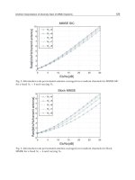
Figure 1 shows the theoretical possible achievable efficiency as a function of the absorber temperature. For simplicity, the absorber
temperature is set equal to the process temperature. In reality, the process temperature is less due to losses. As can be seen from the
1
0.9
0.8
0.7
Dish
η max
0.6
Solar tower
0.5
Parabolic
trough
0.4
0.3
0.2
0.1
0
Flat-plate collector
400
600
800
1000 1200 1400 1600 1800 2000
(Tabsorber = Tprocess) (K)
Figure 1 Upper boundary of solar thermal power plant efficiencies.
Concentrating Solar Power
597
graph, the maximum efficiency increases when the process temperature is increased. Each solar thermal technology has a maximum
efficiency. The highest efficiency is reached for the solar dish. In order to withstand such high temperatures as well as high
temperature gradients, suitable materials have to be chosen. The solar tower reaches efficiencies above 60% and the operation
temperatures match the operating temperatures of conventional power plants. In comparison, the parabolic trough has less
efficiency; however, it has already resulted in a standard commercial application.
Another very useful dimension that characterizes solar thermal systems is the concentration ratio C. It is defined as the ratio of
the collector aperture area to the receiver area. The whole collector field has to be considered.
C¼
collector aperture area
receiver area
Flat-plate collectors have a concentration ratio of 1, parabolic trough and Fresnel collectors about 100, solar towers up to or more
than 1000, and solar dishes around 4000. For example, for the Solar Tower Plant of Jülich (STJ; see Section 3.18.5.1.4) in Germany
with a receiver area of more than 20 m2 and a heliostat field area of approximately 18 000 m2, a concentration ratio of around 900
has been reached.
3.18.2.2
Energy and Mass Balance
In order to thermally analyze a solar thermal concentrating system, the mass and energy conservation law has to be considered for
the whole system as well as for each component. Especially, the components of the solar cycle have to be considered in detail.
The thermal efficiency of solar thermal absorbers is given by the following equation:
ηabsorber ¼ αeff −
εσ s T 4
CS
where ε is the emission coefficient, αeff the effective absorptivity, σ the Stefan–Boltzmann constant, and S the solar input. The
concentrated solar energy received by an absorber is absorbed to a large degree, but losses also occur. The losses at the receiver may
be due to radiation, convection, and conduction, as well as thermal losses occur during the transport of heat transfer fluid (HTF).
A detailed energetic consideration of each solar absorber technology can be viewed in Chapter 3.06.
3.18.2.3
Grid-Connected or Island Systems
Solar thermal concentrated power systems can be connected in grid as well as in island systems. For small island systems, solar dish
systems are a suitable solution. Parabolic trough collectors (PTCs), Fresnel collectors, and solar towers may be grid or island
systems. Together with a thermal storage or after hybridization, dispatchable power can be provided.
3.18.2.4
Recooling
In a condensation power station, a main condenser or a turbine condenser, in which the steam flowing away from the turbine
condenses out, can be used. Condensation heat must be led away from the system, to the ambient. This is done by the circulation of
different coolants. Using different systems, heat is delivered either to the hydrosphere (heat removal directly by the main condenser)
or to the atmosphere (heat removal indirectly by air-cooled heat exchangers).
3.18.2.4.1
Closed-circuit recooling systems
The closed-circuit recooling system is thermodynamically closed. By means of a finned tube bundle heat exchanger, the medium on
the product side is cooled (Figure 2).
The use of finned tubes is necessary, because based on the low heat transfer coefficient of the air, a high air mass flow is necessary.
The large need for air can be avoided by enlarging the air-side heat exchange surface compared with the surface on the coolant side.
The big disadvantage of closed-circuit recoolers is the coolant temperature reached, which is close to ambient temperature. This
affects the energy efficiency of the power station.
3.18.2.4.2
Wet cooling systems
Thermodynamically, this system is described as an open process. The warm coolant is injected into the cooling system and then
conducted through a special fill material. The loss of heat occurs by means of convection and mass transport (Figure 3).
Cooling system
System
Air
Figure 2 Closed-circuit recooling system.
598
Applications
Cooling system
System
Air
Figure 3 Wet cooling system.
In such a system, lower temperatures occur and smaller transfer surfaces can be reached compared with a system using the closedcircuit coolers due to cooling to the wet-bulb temperature. Disadvantages of wet coolers are vapor production and the demand for
additional cooling water.
3.18.2.4.3
Mechanical draft cooling systems
As for air supply, there are two different cooling tower variations, supplying cooling air either by forced or by induced draft to the
system. Both variations are used in the closed-circuit as well as in the wet recooling system. Figure 4 shows different variations of
arrangement.
• Forced draft. A mechanical draft recooling system with a blower-type fan at the intake. The fan forces air into the system. A forced
draft design typically requires more power than an equivalent induced draft design. In combination with a wet recooling system,
the fan on the intake of the cooling tower is more susceptible to complications due to freezing conditions.
• Induced draft. A mechanical draft recooling system with a fan at the discharge, which pulls air through the tower. The fan induces
hot and wet air in combination with a wet cooling system.
3.18.2.4.4
Natural draft cooling towers
In the natural draft cooling tower, the necessary air mass flow is caused by density differences (buoyancy). Figure 5 shows the function
of a natural draft cooling tower with closed- and open-circuit cooling systems. The heat exchange surfaces are right in the lower part of
Hot water
Hot water
Fill
Cold water
Cold water
Induced draft
counterflow tower
Induced draft counterflow
tower with fill
Hot water
distribution
Hot water
Louvers
Fill
Centrifugal
fan
Fill
Sump
Cold water
Forced draft counterflow
tower with fill
Figure 4 Wet cooling tower arrangements. Source: Geo4VA.
Fill
Cold water
Induced draft, double-flow
cross-flow tower
Concentrating Solar Power
599
Warm moist air
Air out
Coolant in
Coolant in
Heat exchanger
Fill material
Convection
Convection and mass transfer
Buoyancy
Coolant out
Air in
Air in
Air in
Air in
Collection basin
Coolant out
Figure 5 Natural draft cooling towers: closed circuit (left) and open circuit (right).
the tower, producing current by buoyancy. Compared with the mechanical draft system, the advantage is that the natural draft cooling
tower does not demand power for the fans. The result is a positive impact on the achieved balance of the whole power station.
The natural draft wet cooling tower works in a similar way as the natural draft cooling tower with closed-circuit cooling system,
but instead of the heat exchanger fill material is installed and the heat transfer mechanism functions in a different way.
3.18.2.4.5
Hybrid cooling towers
The hybrid cooling tower is a combination of a mechanical draft closed-circuit system and a wet recooling system. The warm coolant
is partly injected into the cooling system; the other part is cooled down by an air-driven heat exchanger and can afterward be injected
into the cooling system (Figure 6).
Diffuser
Fan
Mixers
Heat exchanger
Noise attenuator
Drift eliminator
Fill
Rain zone
Noise attenuator
Water basin
Figure 6 Hybrid cooling tower. Source: .
600
Applications
The cooling tower can be operated according to the change in ambient temperature. At a low-level ambient temperature, only the
air driven by heat exchanger is in operation. In case the ambient temperature increases, the wet cooling system can also be activated,
to reach a very low coolant temperature. Hence, problems that occur in winter in the wet cooling systems can be avoided and in
summer very low coolant temperatures can be reached. Moreover, the heat exchanger decreases fogging caused by the wet cooling
system. When applying the hybrid driving mode, coolant consumption is considerably reduced.
3.18.2.4.6
Fan-assisted natural draft cooling towers
The design is similar to the natural draft cooling towers (Figure 7). In addition, big fans are introduced in the lower cooling tower.
This additional air mass flow needs a smaller cooling tower. However, the mass flow caused by buoyancy is still very high, so that
the fans are driven with low speed.
3.18.2.4.7
Air-driven condensers
In the air-driven condenser, the steam flowing away from the turbine condenses directly by means of a surface heat exchanger and
the heat is transported directly to the ambient (Figure 8).
The heat exchanger tubes are finned to ensure better heat transfer. Cooling air supply is realized by mechanical draft. This system
has the advantage that the steam is condensed directly so that no additional recooling system is required, and capital and operating
costs decrease. Furthermore, such systems work without control, because the condensation occurs by itself. The disadvantage is that
the accessible coolant temperature lies at ambient temperature level.
To fix this problem, the air-driven condenser can be combined with a hybrid cooling tower and a conventional surface condenser
which transports the condensation heat to cooling water (Figure 9). This, however, requires higher capital costs. Thus, lower
pressure in the condenser can be reached even if the ambient temperature is high. One such installed air-driven condenser, named
LUKO of GEA Energietechnik GmbH, is shown in Figure 10.
3.18.3 Power Conversion Systems
3.18.3.1
3.18.3.1.1
Solar Only
Steam cycles
At present, most solar thermal power plants convert solar power into electricity applying Clausius–Rankine cycles. These steam
cycles are basically of conventional technology and have only to be adjusted to the needs of the solar system. For example, the steam
generator works with an HTF like thermal oil for the evaporation of water. When integrated with a solar cycle, some adjustments on
the conventional cycle have to be made mainly in the heat recovery steam generator (HRSG), in order to consider the dynamical
behavior of the solar part due to the changing weather conditions.
A steam cycle can be attached to almost all solar thermal systems except the solar dishes. Figure 11 shows the operational scheme
for a parabolic trough system with thermal oil as an HTF in combination with a conventional steam cycle.
Figure 12 shows the molten salt tower system with components of a conventional power plant, such as a steam generator.
Also a Fresnel system can be combined with the steam cycle of a conventional power plant.
Depending on the dimension of the power systems, one, two, or three pressure steam cycles in the steam are used. Taking into
consideration the HTF used, one-cycle and two-cycle systems are applicable in order to transport the heat effectively to the steam
turbine.
The main advantages of the conventional steam cycle are as follows:
Figure 7 Fan-assisted cooling tower. Source: GEA Energietechnik GmbH.
Concentrating Solar Power
Windwall
Counterflow module
Parallel-flow module
Forced draft fan
Steam in
Air removal system
Condensate tank
Figure 8 Two-stage, single-pressure air-driven dispenser. Source: GEA Energietechnik GmbH.
Figure 9 Parallel Condensing system (PAC®). Source: GEA Energietechnik GmbH.
Figure 10 Installed air-driven condenser. Source: GEA Energietechnik GmbH.
601
602
Applications
Figure 11 Process flow diagram of parabolic collector field combined with a steam power cycle.
565 °C
Hot salt
storage tank
Cold salt
storage tank
290 °C
Steam generator
Conventional
EPGS
Figure 12 Process flow diagram of molten salt tower plant. EPGS, electric power generating system. Source: Sandia National Laboratories.
•
•
•
•
Reasonably high efficiency of the steam cycle, especially the steam turbine
High scale of power capacity from 1 MW to more than 1000 MW
Applicable for the temperature ranges of solar thermal power plants
Can be combined with hybrid systems as bottoming cycle to achieve higher efficiencies
The disadvantages are as follows:
•
•
•
•
High water consumption for the cycle and/or for recooling
Personnel need to have knowledge of the complex systems
Can hardly be used as remote automatic power plant
Not applicable for small-scale power plants
High efficiency is reached for large-dimension power plants due to the fact that for these plant sizes the components of the steam
cycles are state of the art. But with appropriate adjustments to the conventional parts, even for small power plants good thermal
efficiencies can be reached, and the high investment of the collector field is compensated.
For the efficiency of a Clausius–Rankine cycle, recooling is important, because the backpressure of the steam turbine reduces the
possible expansion of the steam from high pressure to low pressure (vacuum). The backpressure is dependent on the recooling
temperature. As solar power plants with recooling are located in regions with high ambient temperatures, this may have an impact
when using recooling systems that use ambient air.
Concentrating Solar Power
3.18.3.1.2
603
Organic Rankine cycles
Another alternative to conventional Clausius–Rankine cycles is the organic Rankine cycles (ORCs) used to convert thermal energy
into electric energy. They work in a similar way but use an organic fluid for the cycle. These cycles are applied to lower temperature
heat sources compared with water/steam cycles. ORCs are mainly used in combination with geothermal power or waste heat
recovery in industrial processes. The range of the electrical power output is from some kilowatts to about 10 MW. Additionally,
thermal energy can be produced, which does increase the overall efficiency. Due to the low temperatures, ORCs possess a lower
theoretical Carnot efficiency at a maximum of 30% [1] than water/steam cycles. The temperatures of the working fluids are limited
to about 250–350 °C due to thermal stability thresholds [1]. Working fluids include organic (hydrocarbon) fluids, namely, R-123,
R-134a, R-245fa, R-717 (ammonia), R-601 (n-pentane), R-601a (isopentane), and C6H6 (benzene).
Generally, an ORC consists of components that are also included in a Clausius–Rankine cycle. The cycle consists of an
evaporator, a superheater, a turbine/expander, a condenser behind the turbine, and a pump. Because of the organic fluids and
their different freezing points, usually lower than that of water, the condenser does not work in subatmospheric pressures and is
water- or air-cooled. In this configuration, ORCs with upper cycle temperatures of about 300 °C have an efficiency of about 12.5%
[2]. The efficiency of the basic Rankine cycle can be increased by recuperation and reheating, which lead to efficiencies of 20.5% for
the same boundary conditions [2]. In this case, the expanded fluid at the second turbine stage heats the fluid before entering the
evaporator and is itself cooled down. Reheating takes place after the expansion in the first turbine stage by redirecting the heat to the
boiler.
Additionally, when higher thermal energy source temperatures are available, the combination of two or three ORCs using
different working fluids with different saturation temperatures can increase the overall cycle efficiency.
Reasonably high cycle efficiencies compared with other energy conversion techniques can be obtained by an ORC. Herein, the
high turbine efficiency (up to 85% [1]) is the main advantage. Due to the low turbine speed, low mechanical stress, and absence of
moisture in the vapor nozzles (thus no erosion of the blades), a long lifetime is guaranteed. Furthermore, the ORC has less
operation and maintenance (O&M) costs and can be operated remotely because of the low pressures compared with steam cycles.
Simple start–stop procedures and good part load behavior make the ORC an attractive energy conversion system.
Despite these advantages, the negative aspects have to be mentioned. The limited overall efficiency and the limited plant size due
to the low source temperatures allow ORCs to be used only for certain applications. Using organic fluids may not be an
environmentally friendly option, and some of these are forbidden by the Montreal Protocol as they are capable of destroying the
ozone layer. Furthermore, dykes have to be installed to hinder fluid from entering the ground.
ORCs can work at lower temperatures, so the operating temperature of the parabolic trough can be reduced from about 400 to 300 °C.
This allows to use inexpensive HTFs (e.g., Caloria) and combine it with a two-tank thermal energy storage system. Furthermore, lower
operating temperatures result in lower capital cost for the solar components. By using organic fluids for the power cycle instead of water in
combination with air cooling of the power cycle, the use of water is reduced to only the amount for cleaning the mirror surfaces, which is
about 1.5% of the total water use at the solar electric generating systems (SEGSs) [2]. Another advantage, as mentioned before, is that the
plant operation can be done remotely. This further reduces the O&M costs of solar thermal plants.
The combination of ORC and solar collectors follows a trade-off (Figure 13) between the single efficiencies to gain the
maximum overall system efficiency. Increasing the temperature of the process will lead to a lower collector efficiency, but increases
the ORC efficiency. Choosing the right medium temperature has a great impact on the overall system efficiency.
ORC installations have increased in the last few decades because of the optimization of the efficiency of industrial processes and
the intensive application of renewable energies like biomass and geothermal. At present, the share of different applications in the
ORC market is as follows: 48% biomass, 31% geothermal, 20% waste heat recovery, and 1% solar [3]. The solar thermal share of the
ORC market is still low, but some applications have been installed. A choice of these installations is listed below:
η
Collector efficiency
ORC efficiency
Overall efficiency
T
Figure 13 Trade-off between collector and ORC efficiency. Source: Quoilin S and Lemort V (2009) Technological and economical survey of organic
Rankine cycle systems. In: Proceedings of the 5th European Conference: Economics and Management of Energy in Industry. Vilamoura, Algarve, Portugal,
14–17 April.
604
Applications
Figure 14 Solar ORC in Lesotho. Source: Solar Turbine Group.
• Arizona Public Service (APS) built a 1 MWe concentrated solar power (CSP) plant working with ORC in Arizona in 2006. Ormat
International has supplied the 1.35 MWe gross power block and Solargenix Energy Inc. was the system integrator and the vendor
of the 10 340 m2 parabolic trough field [4]. The ORC runs with n-pentane as the working fluid and the peak solar-to-electrical
efficiency is about 12.1% at the design point. The annual solar-to-electrical efficiency is 7.5% [5].
• Another prototype plant was built by GMK in Germany in 2005. The ORC power output is 250 kWe, with the electrical efficiency
of the system being about 15%. A parabolic trough field has not been built; instead, the solar system has been simulated by a
natural gas boiler [3].
• The Solar Turbine Group developed small-scale systems for remote off-grid applications. Figure 14 shows a 1 kWe system
installed at Lesotho. Such systems have been developed to replace diesel generators in off-grid areas of developing countries.
By using materials available in this country and designing an ORC that runs at medium temperatures, the levelized electricity cost
(LEC) can be lowered (~0.12 $ kWh−1 compared with ~0.30 $ kWh−1 for diesel) [3].
3.18.3.1.3
Gas turbines
Introducing concentrated solar energy into a gas turbine (GT) system implements a new GT power plant concept. The GT can be
combined with a dish/Brayton system as well as a solar tower. The receiver considered in both cases is a pressurized closed
volumetric one. The heat transfer medium is forced through the receiver structure and is heated by convection.
In the combination of the GT with a dish/Brayton system, the solar radiation is focused by the dish concentrator and it enters the
receiver through a quartz window. The window guarantees the closing of a pressure vessel. Air as an HTF enters the combustor and
passes through the receiver, where it is heated up.
If required, an additional burner enables the daily operation of the plant. Hot air enters the turbine where it expands; the exiting
hot air is connected to the GT combustor and the cycle is closed.
When the GT is combined with a solar tower (Figure 15), the receiver absorbs the concentrated solar irradiation and transfers the
solar heat to pressurized air, which can be heated up to 1000 °C. The hot pressurized air from the solar receiver is directly fed into
the combustion chamber of a GT, where natural gas is added to further heat the air to the turbine firing temperature design point.
Solar
unit
Combined
cycle plant
Receiver
Gas
Heliostat
field
Gas
turbine
Figure 15 Scheme of solar hybrid GT system. Source: DLR.
Steam cycle
Concentrating Solar Power
605
The serial connection of pressurized solar air receivers with the combustion chamber of a GT allows a solar hybrid operation that
can compensate for any deficiency in solar radiation. Thus, the power output of the solar-hybrid power plant can be guaranteed,
independent of the sun’s position or meteorological conditions, and still meets the utilities power demand requirements.
Depending on the system configuration and operation strategy, the power output from solar energy can be between 40% and
90%, depending on the design conditions [6].
The concept of solar hybrid GT systems leads to the following advantages:
• High cost reduction potential due to the high conversion efficiency
• Low environmental impact due to low water consumption
• GT Brayton cycle – no cooling water required
• combined cycle configuration – up to 70% less cooling water required
• Reduced land use due to high conversion efficiency, which reduces collector area and land use
• Guaranteed dispatchable power
Different international projects like REFOS and SOLGATE have already been completed. Some are currently ongoing, like
Solugas [7, 8].
The main objective of the Solugas project is to demonstrate the performance and cost reduction potential of a solar hybrid-driven
GT system on a commercial scale. The German Aerospace Centre (DLR) and industrial partners, like GT manufacturer Turbomach
and Abengoa Solar, participate.
3.18.3.1.4
Solar dishes
A dish/Stirling power plant is made of a parabolic dish concentrator, a solar receiver, and a Stirling engine. The system is hybrid, as it
uses fuel to supplement solar power. Figure 16 demonstrates the operational scheme of such a system. When solar energy is
unavailable, the system can operate with fuel alone. Some dish/Stirling units have been tested and show tens or thousands of
operation hours.
The Stirling engine can be replaced by a recuperated GT. In that case, a dish/Brayton system is formed as seen in Figure 17.
Many solar dishes, including Stirling or Brayton, can be combined together to form a solar dish power plant.
3.18.3.2
3.18.3.2.1
Increase in Operational Hours
Hybridization
Through hybridization, for example, by combustion of biofuel, the production of electricity can be increased up to 8600 h. It is
expected that such hybrid power plants will have a high potential for market introduction in the next decade [10].
The concept of solar–fossil hybrid power plants offers a major option for accelerating the market introduction of solar thermal
power technology. The advantage of solar–fossil hybrid power plants, compared with solar-only systems, lies in low additional
investment costs due to an adaptable solar share and reduced technical and economical risks.
Many hybridization options are possible with natural gas combined cycle and coal-fired or oil-fired Rankine plants.
Stirling engine
and generator
Concentrated
sunlight
Solar receiver
and combustor
Parabolic
dish
concentrator
Figure 16 Operational scheme of a dish/Sterling system. Source: Pitz-Paal R, Dersch J, and Milow B (2005) European concentrated solar thermal
road-mapping. SES6-CT-2003-502578 [9].
606
Applications
Generator
Air
turbine
Recuperator
Combustor
Concentrated
sunlight
Compressor
Solar
receiver
Air inlet
Parabolic
dish
concentrator
Air exhaust
Figure 17 Operation scheme of a dish/Brayton system. Source: Pitz-Paal R, Dersch J, and Milow B (2005) European concentrated solar thermal
road-mapping. SES6-CT-2003-502578 [9].
An advantage of hybridization is that the power plant can be made dispatchable and this allows generation of electricity on
demand. Hence, the plant can run more economically. Furthermore, hybridization leads to minimizing or neglecting thermal
storage. Thus, the high costs of such a storage can be minimized.
3.18.3.2.1(i) Integrated solar combined cycle system
A hybrid solar power station is a solar thermal power station that uses a second energy source for heat production, besides the solar
radiation. Non-fossil fuels, hydrogen, methanol, or fermentation gas can be used. These fuels are used when more electric energy is
needed in case of low solar radiation. In addition, thermal energy can be stored to buffer the heat flows temporarily. The integrated solar
combined cycle system (ISCCS; Figure 18) combines a solar parabolic through-collector field with a combined cycle power station.
The heat recovery boiler is modified to enable additional steam production by a solar steam generator or an afterburner. Solar
heat is only partially used for steam production; in the absence of storage technologies, the annual solar heat produced in such types
of power station is less than 20% (Figure 19).
Steam turbine
Fuel
Flue
gas
Condenser
Gas turbine
Waste heat
recovery system
High-pressure
steam
Expansion
vessel
Solar
steam
generator
Feedwater
Deaerator
Figure 18 ISCCS schematic diagram. Source: Flagsol.
Low-pressure
preheater
Concentrating Solar Power
(a)
(b)
300
300
200
Solar
250
200
Steam turbine
MW
250
MW
607
150
100
Solar
Afterburner
Steam turbine
150
100
Gas turbine
50
Gas turbine
50
0
1 2 3 4 5 6 7 8 9 10 11 12 13 14 15 16 17 18 19 20 21 22 23 24
Time (h)
0
1 2 3 4 5 6 7 8 9 10 11 12 13 14 15 16 17 18 19 20 21 22 23 24
Time (h)
Figure 19 (a) Open-load and (b) base-load curves of ISCCS.
3.18.3.2.1(i)(a) Preheating for fossil power plants A solar thermal system may be a heat source, providing necessary heat for a
heat exchanger of a steam power cycle, which might be a water preheater. On sunny days, the solar concentrated system provides the
necessary heat; otherwise, fossil fuels in the conventional power plants take over. For preheating applications, Fresnel collectors,
parabolic troughs, and solar towers are suitable. The collector area is specially dimensioned in order to match the required energy
input. It may be located next to an existing coal or lignite power plant. Integration of a solar field enables reduction of CO2 emission
and saves fossil fuel.
3.18.3.2.1(i)(b) Gas engine Gas engines also enable hybridization of solar thermal power plants. Compared with other engines,
gas engines may be of higher efficiency and there will be less environmental impact when using natural gas and biogas. A gas engine
can work with biogas of low quality, which would be more difficult for GTs. Instead, GTs permit a higher variety in CH4/CO2 mixture.
The advantages of using biogas compared with other biomass fuels are mainly the biomass-to-land use ratio due to the application of
the whole plant, transport of biogas via pipeline, and the utilization in various machines and applications. Also hybridization of solar
thermal power plants with biogas is of interest as the status of a renewable energy conversion plant is maintained.
Gas engines can be combined with parabolic trough as well as with tower power plants. Lower temperatures (in the range of
300 °C to almost 400 °C) of the flue gases of gas engines compared with those of GTs have to be considered. Due to this fact, gas
engines are more applicable for parabolic troughs using thermo fluid. The flue gases of gas engines can also be integrated into other
solar thermal plants, depending on their concept. In power plants running steam temperatures higher than 400 °C, the gas engine
flue gases might be used for preheating. Compared with GTs, gas engines have a lower volume flow-to-installed capacity ratio
because of almost stoichiometric combustion. Therefore, and due to efficiency of about 40% and more, the installed capacity of gas
engines is higher to achieve a certain thermal power output. This capacity can be reached by using one or more engines that are
connected. Possibly engines of capacities up to 100 MWe may be installed to power parabolic trough power plants of 50 MWe. More
engines with less individual capacity can permit a better controllability of part load. Instead, in GTs, the combustion is overstoichiometric, and additionally air is soaked in for cooling the turbine blades.
The use of gas engines for solar thermal power tower plants or Fresnel collectors with direct steam generation (DSG) depends on
the live steam temperatures and the flue gas temperature of the engine. For DSG and power tower plants with water tube receiver
and saturated steam production, the live steam parameters may be at about 400 °C where certain gas engines can produce flue gases
at these temperatures. Nevertheless, even if the temperatures are too low for live steam production, gas engine flue gases can be
heated up by an additional burner or can be used for preheating or evaporation. The flue gases’ energy can be transmitted by a heat
exchanger to the heat transport media or directly to the water/steam cycle. In combination with the open volumetric receiver
concept of solar tower plants, the flue gases can be mixed with hot air which is heated up by the receiver and enter the HRSG. The
hybridization of solar thermal power plants with gas engines predicts a dispatchable power plant which is independent of thermal
storage, although the plant may include one for solar-only operation. At present, such hybridized plants speed up the market
introduction of solar thermal power plants.
3.18.3.2.1(i)(c) Burner Hybridization is also possible with an additional burner in order to provide the steam parameters at the
inlet of the steam turbine.
At the SEGS power plants, the hybridization with a burner was realized. Figure 20 shows the schematic diagram of an optimal
deployment of a burner in a parabolic trough system.
Thermal oil as an HTF is transported through the collector field and heated up. The heat is transported to water, and steam is
produced in a boiler and expanded in the steam turbine, producing electricity. An additional burner provides the steam required on
days with less solar radiation or at night.
The same hybridization may be realized when water/steam is used as an HTF. This concept has the advantage of leaving out heat
exchangers, and is demonstrated in Figure 21.
608
Applications
Figure 20 Additional burner for a PTC power plant. G, generator.
Figure 21 Additional burner in a DSG solar power plant. G, generator.
To achieve the gas parameters at the inlet of the HRSG, at a solar tower system with an open volumetric receiver, for nominal
load even by less solar radiation, a channel burner is included. Figure 22 shows the realization for such a hybrid system.
The burner heats up the preheated air from an open volumetric receiver to the desired temperature [11]. It can be operated in
parallel or instead of the solar air receiver. Parallel means that on a day with little solar radiation, both components can provide the
heat for the HRSG at the same time. In the other operation mode, the hybrid component is only switched on in the night or at times
of no solar radiation.
3.18.3.2.1(i)(d) Gas turbine A GT can be combined with a solar tower with the use of open volumetric receiver. In the position
of the burner, as shown in Figure 22, a GT is placed. The GT is in a position parallel to the receiver. The exhaust gas from the GT is
mixed with the air from the receiver to get the nominal mass flow at a high temperature. After the HRSG, the exhaust gas is
Open volumetric
receiver
Steam
Thermal
storage
Turbine
HRSG
Heliostat field
Air
recirculation
Cold air
Figure 22 Schematic diagram of the Jülich demonstration plant with a channel burner. Source: SIJ.
Concentrating Solar Power
609
recirculated to the receiver or can be passed to a stack. This hybridization concept has the advantages of combined cycles, like high
efficiency, and additional power production by the GT. As fuel, natural gas or biogas (to maintain the status of the plant using
renewable energies) can be used. In addition, the hybridization concepts can be used in different operation modes.
The combination of GT and closed volumetric receiver type for solar tower plants also permits hybridization. The compressed air
is heated up by the concentrated irradiation and directed to the turbine. In case the solar power cannot heat the air to the needed
turbine inlet temperature, a burner can be used to achieve the temperature by additional firing. This plant can also be operated in
case of no solar radiation by using this setup as a conventional GT power plant.
3.18.3.2.2
Storage
Storages are classified as long- or short-term storages, according to their purpose.
While long-term storages are used to compensate for seasonal temperature fluctuations, short-term storages are intended for
periods from a few minutes up to several days. Depending on the energy to be stored, there are a multitude of storage possibilities.
Storage of electrical energy is either difficult to achieve or very expensive. The classic long-term storages in the energy sector are
pumped storage plants.
A thermal storage system for solar power plants is used as a buffer. It stores thermal energy in times of high irradiation and
enables the operation of the power plant after sunset and during periods of reduced solar input or cloud passages. By using storages,
solar thermal power plants also gain the following advantages:
• Conservation of the conventional power plant components (protection of the turbine against increased loading due to constant
starting up and shutting down)
• Cost savings for the power plant components – for example, due to the components of the steam cycle not having to be laid out
for the maximum power rating of the receiver – which results in increased hours of operation of the steam cycle
• Possibility of various start-up strategies
• Enabling the supply of solar electricity at especially profitable times
• Flexibility – due to the storage and steam cycle having the same working temperature, the energy can usually be drawn faster from
the storage and be directly supplied to the steam cycle; thus, warm-up times and delays in the process cycle are avoided
A great advantage of thermal power plants is the ability to store energy in many relatively low-priced ways. Economical thermal
storage is a key technological issue for the future success of solar thermal technologies.
3.18.3.2.2(i) Solid media
The classic method of storing thermal energy is to choose a solid storage medium and increase its temperature by sensible heat
transfer. Thermal storages with hot gases flowing through them have been in industrial operation for many years. These so-called
regenerators are employed in flue gas cleaning and heat recovery in the metal industry.
This principle, as described in Reference 12, is implemented in the Jülich solar tower and serves as a heat storage for the solar
tower power plant with an open volumetric receiver. The principle is depicted in the schematic diagram shown in Figure 40.
During charging, the HTF flows through the storage medium (Figure 23). For unloading, the flow direction is reversed.
A temperature profile may develop over the height of the storage. This principle is illustrated in Figure 24. The steeper the
temperature gradient, the greater the amount of storage medium that can be used for storage. The storage capacity varies mainly
depending on the storage material chosen. In addition, the shape and distribution of the inventory materials are the decisive factors
for the actual storage capacity per storage volume.
As mentioned in Reference 13, packed bed designs appear particularly attractive, but they have additional technical risks
stemming from mechanical loads occurring during cyclic operations. A concrete heat storage developed by DLR offers low-cost
prerequisites for heat storage for parabolic trough power plants with thermo oil as an HTF [14].
3.18.3.2.2(ii) Organic media
The term ‘organic heat transfer media’ describes hydrocarbon compounds as they are used in the ORC processes. Thermo oils used
in current parabolic trough power plants also belong to this media group. Classical methods of heat storage for single-phase HTF are
the one- and two-tank storage systems [15–17].
In the one-tank thermocline storage system, a single tank is used, which contains both the hot and cold heat transfer media.
In order to prevent mixing of hot and cold fluids in the container, a thermocline stratification must be maintained. During charging
of the storage, cold fluid is taken from the bottom of the tank, and after heating it flows back into the tank from the top.
During discharge, the flow direction is reversed. A simultaneous charging and discharging is theoretically possible if there are two
sets of hot and cold pipes. In the two-tank system (hot/cold tank configuration), the hot and cold media are stored in separate tanks.
In this way, a mixing, and therefore an exergy decrease, is prevented. This advantage, however, is achieved only with additional costs
because of the need for two tanks.
3.18.3.2.2(iii) Phase-change materials
Due to their phase-change enthalpy, phase-change materials (PCMs) offer the greatest potential for large storage capacities per storage
volume. In addition, during the entire melting time, this process provides an almost constant source temperature [18]. These materials
have great advantages for operation with dual-phase HTFs. This technology is not as widespread as that of the sensitive heat storages
610
Applications
Storage chamber
Hot air
Cross-sectional area
of honeycomb elements
Honeycomb storage
elements
Z
Y
X
Cold air
Figure 23 Storage layout and honeycomb element.
Storage temperature profile
Temperature
Storage capacity
100%
Storage capacity
0%
Storage height
Figure 24 Temperature profile of the storage for 100% and 0% storage load.
(SHSs). The disadvantage is the usually lower heat transfer coefficient that can develop during loading and unloading. The reason is the
solid–liquid interface, which moves away from the heat transfer surface during loading, causing an increase in the thermal resistance. A
combination of PCM and SHS systems is the focus of current research [19].
There is an ongoing attempt to combine both advantages. Good heat transfer coefficients can be achieved with the SHS
technology, and a high storage capacity can be reached using the latent heat storage (LHS) technology.
First, advanced storage materials based on PCM technology adapted to steam generation/condensation in the range of
200–300 °C have been tested by DLR in Almeria, Spain, in a plant with a power rating of 100 kW.
An expansion to 1000 kW with operating temperatures of 300 °C is being sought as described in Reference 19.
3.18.3.2.2(iv) Adiabatic pressurized air storage
Adiabatic pressurized air storage shows a new and low-cost possibility to store huge amounts of energy [20, 21]. This technology
combines pressurized air storage with a heat exchanger. A standard method is to store pressurized air in caverns. A schematic
diagram is shown in Figure 25.
During the charging process, ambient air is first compressed under high pressure and then in a subsequent step it passes the heat
to a thermal storage system. When discharging, the stored heat is used. The pressurized air leaves the cavern and flows through the
storage where it is heated up. Then the hot pressurized air is passed to a GT and electricity is produced. By this process, no additional
Concentrating Solar Power
611
Air outlet
M
Air
intake
LP
ST
ST
HP
M
LP
HP
ST
Heat storage
Cavern
G
G
Motor
Low-pressure compressor
High-pressure compressor
Steam turbine derivative,
high and medium pressure
Generator
Figure 25 Schematic diagram of an adiabatic pressurized air storage system. Source: Bullough C, Gatzen C, Jakiel C, et al. (2004) Advanced adiabatic
compressed air energy storage for the integration of wind energy. In: Proceedings of the European Wind Energy Conference, EWEC 2004. London, UK,
22–25 November.
heat is required. Since 1978, experience has been gained in the classical pressurized air storage technology [22]. This new technique,
however, needs a pressure-resistant heat storage system (up to 200 bar), which has to withstand long operational periods and
fluctuations of temperature of approximately 550 °C. Efforts for the construction of a 300 MW power plant are being made. The
efficiency is estimated to be about 70% [20].
3.18.3.2.2(v) Others
A high cost factor for all types of storages is the cost of the inventory materials. Considering future locations of solar power plants, raw
sand which is almost free of charge would be an interesting storage medium. The concept of sand as a storage medium for a solar tower
with a volumetric receiver has been evaluated to have high potential by DLR in Cologne (Figure 26). While in a ceramic storage
one-third of the costs incurred are for the storage material, sand would be nearly free of charge and sufficiently available [13].
The key component is the air–sand heat exchanger. In recent years, a concept has been developed in the Solar-Institut Jülich (SIJ),
and a test rig has been constructed [12]. In the cross-flow heat exchanger, sand flow is separated from the airflow channels by
ceramic and woven-metal filter walls. The air flows through the sand bed, thus generating a temperature profile.
The sand which is heated up in the air–sand heat exchanger to approximately 800 °C (not directly irradiated as with a particle
receiver [23]) flows to the hot storage through a downpipe and further to the fluid bed cooler. The fluid bed cooler, a unit which is a
standard component of fluidized bed combustion units, is the driving element of the steam cycle. The generated steam is finally fed
to the steam turbine for power generation. The cooled sand exits from the fluid bed cooler at a temperature of approximately 150 °C
and either returns to the air–sand heat exchanger or is stored in the cold storage tank [12].
3.18.4 Cogeneration
3.18.4.1
Solar Cooling
Solar cooling can be either realized electrically or thermally driven. With respect to CSP technology, in general, both solutions are
technically feasible. But when focusing on cogeneration options of CSP, only thermally driven cooling is relevant. Cooling with
Volumetric
receiver
Air−sand heat exchanger
Cold storage
Tower
Hot
storage
Turbine
Heliostat field
Fluid bed cooler
Figure 26 Sand storage concept for solar power towers. Source: German Aerospace Centre (DLR), SIJ.
612
Applications
solar energy is feasible without the use of ozone-depleting chlorofluorocarbons (CFCs) and helps lower the emission of greenhouse
gases (GHGs). The global cooling demand is steadily increasing and varying. The potential in Europe for solar heating and cooling is
presented in Reference 24.
3.18.4.1.1
Principles and technologies of solar cooling
The driving heat for any thermally driven chiller can be produced by solar energy with the appropriate technology, concentrated or
not concentrated, that allows different temperature levels for the inlet heat. Varying cooling demand and intensity of solar radiation
show the same pattern at many geographical sites which can be regarded as a benefiting coincidence. Another benefit is the fact that
the use factor of the solar appliances (collectors, concentrators, and complete plants) can be easily increased when cogenerating heat
and cold. The variation in principles is huge. Figure 27 is an overview of different groups of solar cooling principles.
3.18.4.1.2
Thermally driven cooling systems
Well-proven thermally driven cooling technologies for cold production are absorption and adsorption chillers. Absorption cooling
uses a liquid sorption material or a solid material (dry absorption). Solar thermal energy changes the refrigerant into a vapor.
Adsorption cooling uses a solid sorption material (water/silica gel or water/zeolite). Solar thermal energy dries out or regenerates
the desiccant. The process is called the desiccant cycle. The cycles can be both continuous and intermittent.
3.18.4.1.3
Absorption chillers
In absorption chillers, a thermochemical process is used to drive a vapor compression cycle. The refrigerant in an absorption chiller
dissolves in an absorbent solution for which it has a high chemical affinity. Two common refrigerant/absorbent combinations are
water and lithium bromide (LiBr–H2O) (used in water-cooled absorption systems) and ammonia and water (NH3–H2O) (used in
air-cooled systems). Thermal energy for the absorption process can be supplied in different ways, for example, by gas burners and by
recovering thermal energy from concentrated solar thermal power plants (cogeneration). The number of heat exchangers within the
absorption chiller distinguishes the system as either single-effect or double-effect absorption chiller. Single-effect absorption chiller
systems consist of an evaporator, an absorber, a generator, a separator, and a condenser and is shown in Figure 28.
The evaporator generates chilled water at 4–10 °C that is pumped to air conditioning units in the air distribution system. Solar
flat-plate, evacuated tube, or parabolic trough collectors can be used to heat water from 77 to 99 °C, which is circulated through the
generator to heat the refrigerant/lithium bromide solution.
Double-effect absorption chiller systems use a high-temperature generator and a low-temperature generator to improve the
thermodynamic efficiency of the absorption cooling cycle. Operation of the evaporator and the absorber is the same as that of the
single-effect system. The high temperature for the heating cycle of a two-stage chiller requires concentrating solar collectors, like
PTCs. Steam units operate with a pressure of 3.5–9 bar, which can be produced directly by a field of trough collectors. In triple-effect
absorption chiller systems, two single-effect absorption circuits are combined. A basic figure to describe the quality of the
conversion of heat into cold is the thermal coefficient of performance (COP). It is defined as the useful cold (Qcold) per unit of
invested driving heat (Qheat). Single-effect lithium bromide chillers operate with thermal COP that is limited to about 0.7.
Double-effect chillers can have thermal COP in the range of 1.0–1.5.
Electric systems
Solar cooling
Photovoltaic effect/
Photovoltaic module:
(vapor compression cycle)
Thermally driven systems
Peltier effect/
Peltier module:
(heat sink/fan combination)
Heat
transformation
Open cycle
Liquid sorbent
Counterflow absorber
Thermomechanical
Closed cycle
Rankine cycle
Liquid sorbent
Absorption:
Vuilleumier cycle
Water/lithium bromide
Water/ammonia
Solid sorbent
Dehumidifier rotor
Fix bed
Solid sorbent
Adsorption:
Water/silica gel
Water/zeolite
Dry absorption
Figure 27 Overview of different processes of solar cooling.
Steam jet cycle
Concentrating Solar Power
613
Refrigerant vapor
Condenser
Separator
Orifice
Evaporator
Chilled water
Lift pipe
Absorber
Cooling water
Heat medium
(solar or gas)
Generator
Heat exchanger
Vapor refrigerant
Liquid refrigerant
Chilled water
Concentrated lithium bromide solution
Cooling water
Dilute lithium bromide/refrigerant solution
Thermal energy
Figure 28 Single-effect absorption chiller. Source: .
3.18.4.1.4
Adsorption chillers
The adsorption cycle needs a lower heat source temperature than the absorption cycle. It operates with silica gel/water
or with zeolite/water as working pairs. Adsorption and desorption take place in reversible cycles. Large heat exchange
surfaces permit a mode of operation close to the thermodynamic limits. An adsorption chiller consists of two or four
chambers, a condenser, and an evaporator. Figure 29 shows a simplified schematic of an adsorption chiller with two
chambers.
In the system shown in the figure, the water, bounded to the silica gel, is driven out of the right chamber while heat is being
transferred into the same stage. Subsequently, the water is liquefied in the condenser. The heat is transferred to the cooling water. In
the low heat chamber (left), the water vapor is adsorbed and the resulting heat is dissipated to the cooling water. The inlet
temperature of the hot water side of an adsorption chiller can be below 75 °C. Thus, solar or waste heat of a low temperature level
can drive an adsorption chiller [25].
3.18.4.1.5
Best-practice examples for solar cooling
The increasing demand for small-scale solar heating and cooling systems results in a number of installed systems for air condition
ing in residential houses or small offices. Within IEA Task 38, a large number of these systems are included in the monitoring and
evaluation procedures [26]. To date, 23 systems have been identified which cover all relevant technologies and a broad range of
different climatic conditions. An overview of installed solar cooling systems worldwide is given in Reference 27. The AEE Institute
for Sustainable Technologies (Austria) runs a project with several partners to demonstrate industrial cooling technology using a
solar-driven steam jet ejector chiller (SJEC). The steam uses water as a refrigerant. An operation between 150 and 200 °C is planned.
Therefore, PTCs are being coupled.
Condenser
Cooling water
2
1
Cooling water
Hot water
(driving heat)
Chilled
water
Evaporator
Figure 29 Schematic of an adsorption chiller. 1, Chamber 1; 2, chamber 2.
614
Applications
400
Required driving temperature TH (°C)
COP / ξCarnot
350
Chilled water
system (e.g.,
fan coil), wet
cooling tower
1.1 / 0.4
1.1 / 0.3
0.7 / 0.4
0.7 / 0.3
300
250
Chilled water
system (e.g.,
fan coil),
air-cooled
Low-exergy
cooling (e.g.,
chilled ceiling)
200
150
1-Axis tracking concentrated
collector
100
50
Flat-plate collector
0
10
15
20
25
High T-lift system
in hot climate
(e.g., ice storage,
air-cooled)
Evacuated tube
collector
30
35
40
45
50
55
Useful temperature lift ΔT = TM − TC (K)
Figure 30 Required heat source temperature as a function of the required temperature lift between required temperature of cold production
(low-temperature heat source) and temperature for heat rejection. Curves refer to different COP/ξCarnot ratios (ξCarnot is the Carnot efficiency factor). Typical
operation temperature ranges of different solar collector technologies are marked by colored areas. The ellipses indicate different system designs [28].
3.18.4.1.6
State of the art of solar cooling
Some of the cooling technologies described are still in the status of pilot projects or system testing. Figure 30 gives an overview,
which compares the different systems with respect to different driving temperatures according to temperature lift showing the
suitable combination of solar collector and cooling technology with their expected COP.
3.18.4.1.7
Market expectations for solar cooling
The growing demand for air conditioning in homes and small office buildings is producing a growing market for different types and
scales of solar-assisted cooling technologies. Basic and applied research in the field of thermally driven cooling is currently
dominated by Japan and, increasingly, China. Europe lagged behind for some time, but due to advances in the efficiency of energy
transformation chains, European R&D institutes and universities have been increasing their efforts on thermally driven cooling
technology, and specifically on its operation in combination with solar energy. Today, Europe is one of the global leaders in the
implementation of solar thermal cooling technology [29].
3.18.4.2
Desalination
A number of CSP systems including the solar tower technology can be used for desalination as well [30]. There are different ways for
the exploitation of the heliostat field for producing clean water (Figure 31).
Heat only
Solar field
Storage
Solar field
Solar
heat
Solar
heat
Combined heat and power
Power only
Grid
Storage
Solar field
Solar
heat
Fuel
Power
plant
Storage
Fuel
Power
plant
Fuel
Heat
MED
MED
RO
Water
Power
Water
Power
Water
Power
Figure 31 Desalination systems combined with solar tower. Source: (2007) AQUA-CSP concentrating solar power for desalination. Final Report by
German Aerospace Center (DLR). Stuttgart, Germany, November.
Concentrating Solar Power
615
Worldwide, a large number of different desalination technologies are available and applied [30]. Only some of these technologies
reached a semicommercial state and can be applied in large units in order to be effectively combined with CSP plants.
At present, either multieffect desalination (MED) systems or reverse osmosis (RO) units are used. The MED system needs
electricity and heat, whereas RO needs only electricity.
MED is a thermal distillation process and has gained attention due to its better thermal performance [31]. MED plants can be
configured for high- or low-temperature operation and can be coupled to a condenser of a steam cycle. The MED process is
composed of a number of elements, which are called effects. As described in Reference 32, the steam from one effect is used in order
to heat another effect which, while condensing, causes evaporation of a part of the salty solution. The produced steam goes through
the next effect, where the same condensing and evaporating phenomena take place.
RO is a membrane separation process that recovers water from a saline solution pressurized to a point greater than the osmotic
pressure of the solution. Membrane layers hold back the salt ions from the pressurized solution, allowing only the water to pass.
Figure 31 shows three different desalination systems combined with a CSP. The first desalination system in combination with a
solar tower (see Figure 31, left) uses only the heat from the solar cycle for the supply of the MED system with heat and the electricity
is provided by the grid. In the second system, the solar tower provides only the electricity necessary for the RO unit (see Figure 31,
middle). The RO plant uses electricity generated by a solar thermal power block to work the pumps. The only high energy
requirement is to pump the feedwater at a pressure above the osmotic pressure. High pressures must be used, typically
50–80 bar, in order to have a sufficient amount of water pass through a unit area of membrane [33].
The third MED system (see Figure 31, right) includes the conventional cycle for supplying the desalination system with heat and
electricity.
These three systems may find application in islands and coastal areas that face water shortage problems.
Desalination plants are to be operated nonstop. Therefore, a solar tower power plant should be in operation day and night [34].
This is possible only with an additional storage unit or with the hybridization of the plant.
3.18.4.3
Off-Heat Usage
In all thermodynamic cycles, it is beneficial to use as much of the heat produced as possible, since this increases the efficiency of the
cycle as a whole. This is especially important in solar thermal power plants, since they are usually built in areas with little access to
cooling water. By reducing the temperature of the waste steam as much as possible, the condensation power required for the
recycling of the process steam can be reduced.
The sources of waste heat in a CSP plant are either steam or heated air, depending on the type of plant and individual
thermodynamic cycles.
Apart from the previously discussed cogeneration applications of desalination and cooling, waste heat can also be profitably
used for other applications. Possibly the simplest and most obvious use of this energy is the same process carried out in every
thermal power plant, that is, the preheating of the feedwater for the power production cycle. This is one of the highest temperature
applications of waste heat and is carried out by a heat exchanger between the steam exiting the steam turbine and the feedwater
entering the boiler.
The applications suitable for the waste heat are determined by its source temperature. Low-temperature heat (<100 °C) is
suitable for hot water and space heating in residential, commercial, and institutional buildings, schools, hotels, and swimming
pools as well as for crop drying.
CSP plants often suffer the disadvantage of variable solar irradiance, which results in unstable steam or hot air parameters. This
could prove to be a severe disadvantage for applications such as crop drying, since these require very precisely controlled air
temperatures. However, the advantage of these lower temperature applications is that even with fluctuating power process
parameters, low-temperature applications (of up to approximately 100 °C) are practically always sustainable.
Higher temperature waste heat (>100 °C) can be used for industrial processes, for example, in the paper and food industries and
sterilization.
In the best-case scenario, solar tower power plants will be run on a combined cycle similar to many modern fossil-fueled power
plants, with a GT topping and a steam turbine bottoming cycle. Only then will the true potential of the technology be harnessed. In
this case, the waste heat of the GT will be the energy supply for the steam production for the steam turbine, and waste heat from
both heated air and steam will be readily available.
A further possibility for central receiver power plants is that waste heat may be obtained from the peripheral areas of the receiver,
where air can be heated to 200 or 300 °C, containing enough thermal energy to drive waste heat processes but not enough to
produce power in a steam turbine or GT.
3.18.5 Examples
3.18.5.1
3.18.5.1.1
Commercial
SEGS
In the years between 1985 and 1991, the nine commercial parabolic trough power plants SEGS I–IX were commissioned in
California, USA. In total, the plants generate an electrical power of 354 MWe, which is fed into the grid. The first of the plants, SEGS I,
616
Applications
Figure 32 The parabolic troughs used in the SEGS. Source: Sandia National Laboratories.
generates 13.8 MWe, the plants SEGS II–VII generate 30 MWe, and plants SEGS VII–IX deliver 80 MWe. The reflective aperture area
varies between 83 000 m2 for SEGS I and 484 000 m2 for SEGS IX.
The parabolic troughs which are used in the SEGS plant are shown in Figure 32.
For these plants, no thermal storage system is installed. However, all nine plants are operated in gas hybrid mode, that is, in a gas
operation that enables a continuous plant operation during periods of overcast or night hours. When in gas operation mode, the
steam quality is improved. As an example, SEGS IX produces a steam temperature of 371 °C at a pressure of 100 bar in solar mode,
but a far higher steam temperature of 510 °C at a pressure of 105 bar is produced in gas mode. However, the solar energy is already
sufficient to generate superheated steam for the plants SEGS II–IX when in solar mode. Figure 33 shows a view of the SEGS
parabolic trough system.
3.18.5.1.2
Andasol 1–3
In Andalusia, Spain, Europe’s first parabolic trough power plant – Andasol 1 – with an electrical power capacity of 50 MWe was
constructed, which – with an area of 510 000 m2 – has the largest collector area in the world when compared with other parabolic
trough-type power plants. It has been planned to construct two more similar plants with the same electrical power output as
Figure 33 A view of the SEGS parabolic trough system. Source: Sandia National Laboratories.
Concentrating Solar Power
617
Figure 34 A view of Andasol 1 and Andasol 2. Source: ESTELA.
Andasol 1, which will be named Andasol 2 and Andasol 3. Figure 34 shows both Andasol 1 and Andasol 2 parabolic trough power
plants.
The field size of each of the three power plants is 510 120 m2. A total of 209 664 mirrors and 22 464 receivers (absorption pipes),
each with a length of 4 m, will be installed.
A heat storage system using 28 500 tons of molten salt (mixture of potassium, sodium, and nitrate salts) consisting of a hot salt
and a cold salt tank will deliver a storage capacity of 7.5 peak load hours when using the stored heat for electricity generation. This
enables the operation of the power plant well into the night hours and allows the buffering of short and longer periods of cloud
passages or overcasts.
The size of the solar field is large enough so that there is sufficient collector area for running the plant’s steam turbine at nominal
load and also for simultaneously charging the thermal storages during the day. In the two-tank system, the molten salt in the hot salt
tank is heated up to 390 °C, and by keeping a minimal temperature of 290 °C, solidification of the salt is prevented. Figure 35
shows the schematic diagram of the Andasol power plant. With the aid of the thermal storage, 3500 peak load hours of operation
should be realized [35].
The thermal storage system is being loaded during the day. During the night, the power plant can be operated with the
stored energy.
3.18.5.1.3
PS10, PS20
The plant Planta Solar 10 (PS10), on the Plataforma Solar de Sanlúcar la Mayor (PSSM), has been connected to the grid since June
2007. It is located near Seville, Spain, and went into operation in 2006. It delivers a nominal gross power of 11.5 MWe and produces
an estimated 24.3 GWh of electricity per year – enough to supply 6000 households. A total of 624 heliostats, each with a surface area
of 120 m2, concentrate the incident direct normal irradiation (DNI) onto a saturated steam receiver.
4
1
2
3
5
Figure 35 Schematic diagram of the Andasol power plant. Source: Solar Millennium AG. 1, Solar collector field; 2, storage; 3, heat exchanger; 4, steam
turbine; 5, condenser.
618
Applications
Figure 36 Bird’s-eye view of PS10. Source: (2006) 10 MW solar thermal power plant for southern Spain. Final Technical Progress Report. November.
This direct evaporation receiver uses water/steam as an HTF and is installed at a height of 100 m from the foot of the tower, which
has a total height of 115 m. Figure 36 provides a bird’s-eye view of PS10. The heliostat field has a total area of 75 216 m2. The
heliostats are positioned in a north-only array in 35 concentric rows [36].
The PS10 solar tower was the first commercial solar tower in Europe. PS10 has been designed on a very conservative approach.
The schematic diagram of the plant is shown in Figure 37.
It works on a conventional and reliable concept based on direct saturated steam generation in the receiver. The generated
steam leaves the receiver in saturated state at 250 °C, at a pressure of 40 bar, and is passed over a steam turbine, whose shaft drives
the generator to produce electricity. The operational availability of the plant in the first months, between 21 June 2007 and
24 October 2007, was 98%.
A thermal storage allows the buffering of cloud passages for 50 min, however, only at half of the turbine workload [36]. Spanish
law allows for a gas cocombustion of up to 15%. On clear days such as those referred to above, no cocombustion is necessary.
However, on days of variable DNI, cocombustion guarantees constant and reliable operation of the plant. During the night, the
plant shuts down. By the operation of the plant, approximately 20 000 tons of CO2 emissions are avoided per year.
PS20 is located right next to PS10 and went into operation in 2009. It generates 20 MWe gross power with an energy turnover of
50 600 MWh a−1. A direct evaporation receiver, also using water/steam as an HTF, is installed at the top of the 161 m tower. The
heliostat field consists of 1255 heliostats, each with a reflective mirror area of 120 m2, totaling to an area of 150 000 m2. The
heliostats are positioned in a north-only array in concentric rows.
Solar receiver
Steam
drum
Steam
40 bar, 250 °C
Turbine Generator
11.0 MWe
Steam storage system
Condensater
0.06 bar, 50 °C
Heliostat field
Figure 37 Schematic diagram of PS10. Source: (2006) 10 MW solar thermal power plant for southern Spain. Final Technical Progress Report. November.
Concentrating Solar Power
619
The generated steam leaves the cavity receiver in saturated state at 250–300 °C at a pressure of 45 bar and is passed over a steam
turbine. A thermal storage allows the buffering of cloud passages for 1 h.
3.18.5.1.4
STJ
In Germany, the construction of a 1.5 MWe solar tower power plant began in 2008. It has been operational since December 2008
and started the production of electricity in the spring of 2009.
Professor Bernhard Hoffschmidt was the initiator of the project and he set the basis for the realization of the construction of the
first solar tower power plant, which uses air as an HTF. The plant as seen in Figure 38 was built by Kraftanlagen München and is
operated by the local utility Stadtwerke Jülich. The SIJ of the Aachen University of Applied Sciences and the DLR conduct the
accompanying research. The location of Jülich was chosen not only because it is close to the research institutions involved but also
because of its fluctuating direct solar radiation that allows and requires investigation of the system operation strategy under
transient conditions – especially in combination with thermal storage.
The objective of the solar power tower project in Jülich is to demonstrate the entire system. The whole venture is funded by the
finance ministries of the states of North Rhine-Westphalia and Bavaria and the German Ministry of Environment.
The Jülich central receiver plant has been designed to deliver up to 11 MWe of thermal energy, which will supply the grid with a
nominal power of 1.5 MWe. Figure 39 shows a bird’s-eye view of the STJ. The concentrator system consists of 2150 sun-tracking
heliostats of about 8 m2 reflective surface each and reflects the sunlight onto a 22 m2 receiver aperture in the shape of an inclined
segment of a cylinder. The applied open volumetric receiver technology is used to heat up ambient air to high temperatures for
steam generation in a boiler of a conventional steam turbine cycle. The porous absorber located at the top of a 60 m tower traps the
highly concentrated solar radiation inside the structure, allowing the heat to be transferred to air very effectively. The receiver is
made up of identical subreceivers, in which the absorber modules can easily be exchanged in case of failure or to test innovative
modules [12].
The advantages of this technology are simplicity and scalability, the ability to include a thermal storage, the low thermal capacity
(quick start-up), and a high efficiency potential due to high achievable temperatures.
Figure 38 The STJ in operation. Source: Kraftanlagen München GmbH.