Volume 2 wind energy 2 10 – electrical parts of wind turbines
Bạn đang xem bản rút gọn của tài liệu. Xem và tải ngay bản đầy đủ của tài liệu tại đây (12.89 MB, 60 trang )
2.10
Electrical Parts of Wind Turbines
GS Stavrakakis, Technical University of Crete, Chania, Greece
© 2012 Elsevier Ltd. All rights reserved.
2.10.1
Introduction
2.10.2
Power Control
2.10.2.1
Pitch Control
2.10.2.1.1
Theory and implementation
2.10.2.1.2
Active stall-controlled wind turbines
2.10.2.2
Yaw System
2.10.3
Electricity Production
2.10.3.1
The Generator
2.10.3.2
Wind Turbine Generators
2.10.3.2.1
Asynchronous (induction) generators
2.10.3.2.2
Synchronous generators
2.10.3.3
Power Electronics
2.10.3.3.1
Harmonics
2.10.3.3.2
Ride through
2.10.3.3.3
Fixed-speed systems
2.10.3.3.4
Variable-speed systems
2.10.4
Lightning Protection
2.10.5
Small Wind Turbines
2.10.6
Outlook
2.10.7
Wind Turbine Industry
2.10.7.1
Major Wind Turbine Manufacturers
2.10.7.1.1
Vestas
2.10.7.1.2
Enercon
2.10.7.1.3
Gamesa
2.10.7.1.4
GE Energy
2.10.7.1.5
Siemens
2.10.7.1.6
Suzlon
2.10.7.1.7
Nordex
2.10.7.1.8
Acciona
2.10.7.1.9
REpower
2.10.7.1.10
Goldwind
2.10.7.1.11
WinWind
2.10.7.1.12
Windflow
2.10.7.1.13
Clipper
2.10.7.1.14
Fuhrländer
2.10.7.1.15
Alstom
2.10.7.1.16
AVANTIS
2.10.7.1.17
Sinovel
2.10.7.2
Subproviders
2.10.7.2.1
ABB
2.10.7.2.2
Weier
2.10.7.2.3
VEM
2.10.7.2.4
Phoenix Contact
2.10.7.2.5
Ingeteam
2.10.7.2.6
Maxwell
References
Further Reading
Relevant Websites
270
272
273
273
276
277
279
279
281
281
285
294
295
295
295
297
298
301
303
306
306
306
309
310
313
314
314
317
317
319
322
322
322
322
323
323
324
324
324
324
324
324
325
325
327
328
328
328
Comprehensive Renewable Energy, Volume 2
269
doi:10.1016/B978-0-08-087872-0.00211-0
270
Electrical Parts of Wind Turbines
Glossary
Blade The part of a wind generator rotor that catches the
wind.
Horizontal Axis Wind Turbine (HAWT) A ‘normal’ wind
turbine design, in which the shaft is parallel to the ground,
and the blades are perpendicular to the ground.
Hub The center of a wind generator rotor, which holds the
blades in place and attaches to the shaft.
Induction motor An AC motor in which the rotating
armature has no electrical connections to it (i.e. no slip
rings), and consists of alternating plates of aluminum and
steel.
Nacelle The protective covering over a generator or motor.
Permanent magnet A material that retains its magnetic
properties after an external magnetic field is removed.
Pulse Width Modulation (PWM) A regulation method
based on Duty Cycle. At full power, a pulse-width
modulated circuit provides electricity 100 percent of the
time. At half power, the PWM is on half the time and off
half the time. The speed of this alternation is generally
Nomenclature
A(γ(t)) turbine rotor swept area (time-varying due to yaw
error)
B magnetic flux
CP power coefficient
E electric field intensity
E electromotive force
fe electrical frequency
N number of core windings
ns rotor synchronous speed
P, Pm mechanical power
very fast. Used in both solar wind regulators to efficiently
provide regulation
Rotor (1) The blade and hub assembly of a wind
generator. (2) The disc part of a vehicle disc brake. (3) The
armature of a permanent magnet alternator, which spins
and contains permanent magnets.
Slip ring Devices used to transfer electricity to or from
rotating parts. Used in wound-field alternators, motors,
and in some wind generator yaw assemblies.
Tip Speed Ratio (TSR) The ratio of how much faster than
the wind speed, the blade tips are moving.
Transformer Multiple individual coils of wire wound on a
laminate core. Transfers power from one circuit to another
using magnetic induction. Usually used to step voltage up
or down. Works only with AC current.
Yaw Rotation parallel to the ground. A wind generator
yaws to face winds coming from different directions.
Wind generator A device that captures the force of the
wind to provide rotational motion to produce power with
an alternator or generator.
p number of generator pole pairs
R turbine rotor radius
S slip
v(t) hub-height uniform wind speed across the rotor disk
γ(t) rotor yaw angle
η flux linkage
θ(t) blade i pitch angle
λ tip speed ratio
ρ air density
ω(t) rotor angular velocity (mechanical)
2.10.1 Introduction
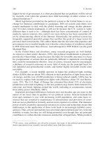
The quest of man for harnessing wind energy goes back into the centuries. Windmills have been used for many purposes but it is
only lately that the wind power has been effectively exploited to produce electricity (Figure 1). Specifically, during the past 20 years,
the wind power industry has evolved into the most important renewable energy sector.
A wind turbine is a complex machine. In order to design efficient and optimally operating wind turbines, knowledge from
diverse scientific fields is required: aerodynamics, mechanical engineering, electrical and electronic engineering, materials and
industrial engineering, civil engineering, meteorology, and automatic control among others.
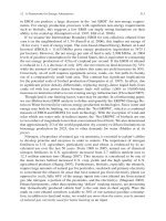
A typical grid-connected wind turbine installation is shown in Figure 2. Though wind turbines can be operated in isolation, this
configuration is of diminishing concern. Large offshore wind parks, comprising 10 MW wind turbines, seem to be the renewable
future.
As seen in Figure 2, a typical wind turbine is erected on solid, concrete foundation and properly earthed. Its output of 690 V is
connected through a transformer station to the 20 kV grid line. The wind turbine itself consists of the main tower, its three blades,
and the nacelle. Inside the nacelle and the tower base are housed the various electrical and electronic parts necessary for the efficient
and safe conversion of wind power to electrical energy. These include the power controls (pitch and yaw), the generator, and the
power electronics. This is a typical example that is not always followed. The transformer station, for example, may be housed in the
tower base.
The ‘electrical system’ of a wind turbine comprises all components for converting mechanical energy into electric power, as well
as auxiliary electrical equipment and the control and supervisory system. The electrical system thus constitutes the second essential
subsystem, following the mechanical one, in a wind turbine (Figure 3).
Electrical Parts of Wind Turbines
271
Figure 1 Seventeenth-century flour mill rebuilt by Acciona at the Guerinda wind park, Navarre, Spain. From Acciona leaflet, www.acciona-energia.com/.
- Clima sensors
- Aviation lights
- Antennas
Rotorblade
Nacelle
Cooling system
Hub
- Generator
- Brake
- Gearbox
- Topbox
- Hydraulic
- Pitch control unit
- Axis cabinet
- Battery backup
- Drives
Yaw drive
Tower
Transformer
station
Foundation
e.g., 20 kV/690 V
- Low-voltage distribution panel
- Main control cabinet
- Inverter technology
- Wind park communication
Cable route
Figure 2 Grid-connected wind turbine.
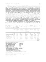
The main components of the electrical subsystem are shown in Figure 4. They will be subsequently analyzed in functional order,
that is, the power control/positioning components (pitch and yaw motors) first, followed by the generator, the power electronics
and grid connection, and finally, the lightning protection elements.
From the electrical engineering point of view, wind turbines are nothing more than electricity-generating power plants, like
hydroelectric ones or diesel-powered. Their electrical systems are similar and must meet the common standards for systems
connected to utility grids. Therefore, similar safety, supervision, and power quality standards must be met.
Grid operation requirements are laid out by international and local institutions. On the global level, the International
Electrotechnical Commission (IEC) has issued a set of general conditions that must be met by the wind farm operators.
272
Electrical Parts of Wind Turbines
Electrical power
Mechanical power
Wind power rotor
Power conversion
and control
Gearbox
(optional)
Power convertor
(optional)
Generator
Power
transmission
Power
transformer
Power conversion
and control
Supply grid
Power conversion and
Power transmission
Figure 3 Subsystems of a wind turbine. From Blaabjerg F and and Chen Z (2006) Power Electronics for Modern Wind Turbines. San Rafael, CA: Morgan
& Claypool.
3
2
5
6
1
9
4
12
8
7
10
13
11
14
15
1. Blades
2. Rotor
3. Pitch
4. Brake
5. Low-speed shaft
6. Gear box
7. Generator
8. Controller
9. Anemometer
10. Wind vane
11. Nacelle
12. High-speed shaft
13. Yaw drive
14. Yaw motor
15. Tower
Figure 4 Wind turbine electrical parts.
Design of wind turbines is aimed at optimum operation, that is, at maximizing conversion of wind energy to electric power,
while maintaining fault-free or fault-tolerant working conditions. Therefore, a wind turbine’s performance must be judged on three
factors:
1. Efficiency of wind power use (through the use of pitch and yaw control and generator selection)
2. Reliability (e.g., lightning protection)
3. Safety (grid connection regulations compliance).
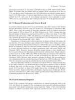
Wind turbines have been rapidly evolved in the past years. Though a classification of various implementations may seem a little
risky, nevertheless it may serve as a useful guide. In Figure 5 is shown such a possible picture.
2.10.2 Power Control
Wind turbines are designed to produce electrical energy as cheaply as possible. Wind turbines are therefore generally manufactured
so that they yield maximum output at wind speeds around 15 m s−1 (30 knots or 33 mph). It does not pay to design turbines that
maximize their output at stronger winds, because such strong winds are rare. In case of stronger winds, it is necessary to waste part of
Electrical Parts of Wind Turbines
273
Mechanical energy source
fixed/variable speed
Input
Transmission
Gearbox
Direct drive
Heat loss
dump load
Machine
type
Multipolar synchronous
and novel machines
Conventional
synchronous machines
Induction machines
Power
conversion
Wound rotor
(field control)
Rotor
Permanent
magnet
Stator
Cage
rotor M/C
Wound rotor or
brushless DF
Wound
Grid
connection
Large PE
converter
Output
Electrical energy source
Fixed frequency or DC
Small PE
converter
Figure 5 Wind turbine classifications. Modified from Wallace AK and Oliver JA (1998) Variable-speed generation controlled by passive elements.
International Conference on Electric Machines. Istanbul, Turkey, 2–5 September [1].
the excess energy of the wind in order to avoid damaging the wind turbine, while in case of weaker speeds some sort of speed
regulation is desirable. All wind turbines are therefore designed with some sort of power control.
There are different ways of doing this safely on modern wind turbines:
• Pitch control
• Stall control (passive or active)
• Yaw control.
2.10.2.1
Pitch Control
Pitch control refers to altering the pitch angle of the wind turbine’s blades so that the rotor speed, and hence the rotor torque and
generated electrical energy are kept at desired levels. This is one way to engineer a ‘constant-speed’ wind turbine, and can be
implemented either by mechanical (hydraulic) or electrical (motor) mean. The latter is mostly employed at present, since,
additionally, it is used to control each blade independently (Figure 6). Pitch control is also a safety mechanism since it can limit
operating levels to the maximum of the given machine.
2.10.2.1.1
Theory and implementation
The ability of a wind turbine to extract power from wind is a function of three main factors:
1. Wind power availability
2. Power curve of the machine
3. Ability of the machine to respond to wind perturbations.
The equation for mechanical power, Pm, produced by a wind turbine is given by,
�
�
ωR
; θ AðγÞv3
Pm ¼ 0:5ρCp
v
½1
274
Electrical Parts of Wind Turbines
Figure 6 Pitch control.
where ρ is air density (kg m− 3), θ is blade pitch angle (rad), γ is rotor yaw angle (rad), v is wind velocity (m s−1), ω is rotor angular velocity
(rad s−1), R is rotor diameter (m), A(γ) is wind turbine rotor swept area (m2), Cp(ωR/v, θ) is power coefficient, and ωR/v = λ is tip speed
ratio (TSR).
Looking at eqn [1], it is seen that in an actual turbine, power can be regulated through pitch angle, rotor speed, and yaw angle,
and all other parameters being exogenous. It is interesting to note, however, that air density affecting power production is not the
same in all wind sites since it decreases with increasing altitude. Excluding yaw variation, Figure 7 shows a typical power surface
0.5000
0.4000
0.3000
0.2000
0.4000−0.5000
0.1000
0.3000−0.4000
0.0000 Cp
0.2000−0.3000
−0.1000
0.0000−0.1000
0.1000−0.2000
−0.1000−0.0000
−0.2000
−0.3000
−0.4000
−0.2000−0.1000
−0.3000−0.2000
−0.4000−0.3000
−0.5000−0.4000
−5
−2
1
4
7
10
13
16
19
22
25
28
13.0
10.0
TSR
11.5
1.0
2.5
4.0
5.5
7.0
8.5
−0.5000
Pitch
Figure 7 Power vs. pitch angle/TSR for NREL’s CART machine. From Wright AD and Fingersh LJ (2008) Advanced control design for wind turbines
part I: Control design, implementation, and initial tests. Technical Report NREL/TP-500-42437, March 2008: National Renewable Energy Laboratory,
Golden, Colorado, USA.
Electrical Parts of Wind Turbines
275
plotted for various pitch angles and TSRs [2]. Such a surface is usually determined through simulation by using an aerodynamics
code such as WT_Perf [3].
Power limitation in high winds is typically achieved by using pitch angle control. This action, also called ‘pitch-to-feather’, which
corresponds to changing the pitch value such that the leading edge of the blade is moved into the wind (increase of θ). The range of blade
pitch angles required for power control in this case is about 35° from the pitch reference. Therefore, for safe regulation, the pitching
system has to act rapidly, with fast pitch change rates of the order of 5° s−1 resulting in high gains within the power control loop.
2.10.2.1.1(i) Implementation
On a pitch-controlled wind turbine, the turbine’s electronic controller checks the power output of the turbine several times per
second. When the power output becomes too high, it sends an order to the blade pitch mechanism that immediately pitches (turns)
the rotor blades slightly out of the wind. Conversely, the blades are turned back into the wind whenever the wind drops again.
Presently, pitch motors are of very compact design. They are mounted on the outside flange ring of each blade (Enercon E-40,
Figure 8) or inside the rotor hub (Lagerway, Figure 9). Meteorological data from anemometers and sensors atop the nacelle
measure wind speed and other environmental conditions. The power supply, data, and control signals for the pitch system are
transferred by a slip ring from the nonrotating part of the nacelle, or stationary-enclosed pivot behind the hub. The slip ring is
Electrical
blade pitch motor
Figure 8 Enercon’s pitch control. From Enercon, www.enercon.de.
Figure 9 Blade pitch system inside the rotor hub (Lagerwey LW-72). From Lagerwey, www.lagerweywind.nl.
276
Electrical Parts of Wind Turbines
Figure 10 Weier 10 kW pitch motor. From Weier, />
Figure 11 Bosch Rexroth Mobilex GFB pitch motor. From Bosch, .
connected to a central control unit, which includes clamps for distributing power, and control signals for the individual blade drive
units. Each blade drive unit consists of a switched-mode power supply, a field bus, the motor converter, and an emergency system.
Pitch motors are manufactured in various sizes to suit wind turbines specifications. Output torques range from 3 to 1100 kNm,
with corresponding ratios from 60 to over 1600 (Figures 10 and 11).
In case of power failure, emergency operation via batteries or capacitor bank is employed. ‘Maxwell Techonologies’ has recently
introduced a series of ultracapacitor modules that promise a simple, solid state, high-reliability alternative to batteries for energy
storage in this type of burst power application. Ultracapacitors offer excellent performance, with wide operating temperature range,
long life, flexible management, and reduced system size; they are cost-effective as well as highly reliable, particularly when designed
with a total systems approach (Figure 12).
2.10.2.1.2
Active stall-controlled wind turbines
An increasing number of larger, fixed-speed wind turbines (1 MW and up) are being developed with an ‘active stall’ (also called
‘negative pitch’) power control mechanism.
Technically, the active stall machines resemble pitch-controlled machines, since they have pitchable blades. In order to get a
reasonably large torque (turning force) at low wind speeds, the machines will usually be programmed to pitch their blades much
like a pitch-controlled machine at low wind speeds (often they use only a few fixed steps depending upon the wind speed).
When the machine reaches its rated power, however, an important difference from the pitch-controlled machines is evident: if
the generator is about to be overloaded, the machine will pitch its blades in the opposite direction by a few degrees (3–5°) from
what a pitch-controlled machine does. In other words, it will increase the angle of attack of the rotor blades in order to make the
blades go into a ‘deep stall’, thus wasting the excess energy in the wind.
Only small changes of pitch angle are required to maintain the power output at its rated value, as the range of incidence angles
required for power control is much smaller in this case than in the case of pitch control. Compared to the pitch-to-feather technique,
Electrical Parts of Wind Turbines
277
Figure 12 Ultracapacitor. From Maxwell, />
the travel of the pitch mechanism is very much reduced; significantly greater thrust loads are encountered, but the thrust is much
more constant, inducing smaller mechanical loads.
Additionally, in active stall one can control the power output more accurately than with passive stall, so as to avoid overshooting
the rated power of the machine at the beginning of a gust of wind. Another advantage is that the machine can be run almost exactly
at rated power at all high wind speeds. A normal passive stall-controlled wind turbine will usually have a drop in the electrical power
output for higher wind speeds, as the rotor blades go into deeper stall.
Typical active stall representatives are the Danish manufacturers Bonus (1 MW and over) and NEG Micon (1.5 and 2 MW).
2.10.2.2
Yaw System
The rotor axis of a wind turbine rotor is usually not aligned with the wind, since the wind is continuously changing its direction (Figure 13).
The yawed rotor is less efficient than the nonyawed rotor and so it is vital to be able to dynamically align the rotor with the wind
(Figure 14). Furthermore, unaligned rotors impose higher loads on the blades, causing additional fatigue damage. The output
power losses can be approximated by,
ΔP ¼ αcosðγÞ
½2
where ΔP is the lost power, γ the yaw error angle, and α a suitable constant (Figure 14).
For these reasons, almost all horizontal-axis upwind turbines use forced yawing, that is, a mechanism which uses electric motors
and gearboxes to keep the turbine yawed against the wind (Figure 15). Yaw control usually includes several drives and motors to
distribute gear loading.
Active yaw is especially useful in providing maximum adaptability in complex terrains. The image in Figure 16 shows the yaw
mechanism of a typical 750 kW machine seen from below, looking into the nacelle.
z
y
x
γ
Figure 13 A wind turbine yawed to the wind direction.
278
Electrical Parts of Wind Turbines
0.6
0.4
Cp max
0.2
0
0
20
40
60
Yaw angle (degrees)
Figure 14 Maximum power coefficient variation with yaw angle γ.
Figure 15 Yaw control.
Figure 16 Yaw mechanism. From Windpower, www.windpower.org.
80
Electrical Parts of Wind Turbines
279
We can see the yaw bearing around the outer edge, and the wheels from the yaw motors and the yaw brakes inside. The yaw
mechanism is activated by the electronic controller that checks the position of the wind vane on the turbine several times per
second, whenever the turbine is running. However, in order to prevent large gyroscopic loads generated by the rotating rotor, the
yaw rate is usually kept very low. Also the nacelle is often parked and the yaw drive is not operated unless the wind direction change
reaches some predefined minimum.
In a novel approach described in Reference 4, a new yaw control technique through actively varying blade pitch angles is
presented. It focuses on the feasibility of active yaw control through periodic state-space individual pitch control on the
WindPACT 1.5 MW three-bladed upwind turbine. The periodic control technique has been used in many other control
applications, particularly in the aerospace field. As the dynamic behavior of wind turbines is often periodic with the rotor
revolution, due to asymmetric wind inflow, the control of turbine motion is more effective with periodic feedback gains.
With the development of periodic state-space control and individual pitch algorithms, possibilities of controlling yaw
through pitching the blades is made possible. One obvious benefit from controlling yaw through pitching the blades is
that the motorized yaw drive can be removed. In addition to this, pitching the blades to yaw the rotor essentially takes
advantage of asymmetric aerodynamic loads on the rotor plane. This means the rotor will be working with the wind through
the blades instead of receiving rotational moments from the yaw motor. This could result in smoother continuous yaw
responses and possibly a reduction in loads.
2.10.3 Electricity Production
To produce electricity, a wind turbine must conform to ‘power quality’ standards, such as voltage stability, frequency stability, and
the absence of various forms of electrical noise (e.g., flicker or harmonic distortion) on the electrical grid. To accomplish this, a
typical wind turbine’s electrical system comprises a series of subsystems as shown in Figure 17.
2.10.3.1
The Generator
In a wind turbine, the generator plays a central role in the functional chain, since it is the actual ‘converter’ of mechanical into electric
energy. However, since it has to face a highly fluctuating torque load, supplied by the wind turbine rotor, it is significantly different
from other generators used in electrical grids.
It is outside the scope of this chapter to give a detailed description of how generators work, but only the most important features
will be outlined. The interested reader can consult any standard textbook for further insight, as for example [5].
Generators are known by many names: DC (direct current), synchronous, induction, permanent magnet (PM), brushless, and
so on. Although, these different types look dissimilar, the physical properties underlining their behavior are quite similar: in fact
the torque-producing characteristics of all types stem from the fact ‘the flux distributions of the stator and the rotor tend to align’.
The generator operation is based on the principle of ‘electromagnetic induction’ discovered in 1831 by Michael Faraday, a British scientist.
Faraday discovered that if an electric conductor, like a copper wire, is moved through a magnetic field, electric current will flow (be induced) in
the conductor. So the mechanical energy of the moving wire is converted into the electric energy of the current that flows in the wire.
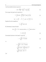
Faraday’s law can be stated in mathematical terms as,
∮ Eds ¼ −
C
d
∫ Bda
dt S
½3
where E is the electric field intensity around the closed contour C and B is the magnetic flux.
Equation [3] states in words that the line integral of the electric field intensity E around a closed contour C is equal to
the rate of change of the magnetic flux passing through that contour. In magnetic structures with windings of high electrical
conductivity (Figure 18), it can be shown that the E field in the wire is extremely small and can be neglected, so that the
left-hand-side (LHS) of eqn [3] reduces to the negative of the induced voltage or ‘electromotive force’ e at the winding
terminals. Additionally, the flux on the right-hand-side (RHS) of eqn [3] is dominated by the core flux φ. Since the winding
links the core flux N times, eqn [3] reduces to,
eðtÞ ¼ N
Generator
G
dφðtÞ dηðtÞ
¼
dt
dt
Voltage source inverters
MV
transformer
=
~
–
Figure 17 Wind turbine electrical system.
½4
~
0.4/20 kV
280
Electrical Parts of Wind Turbines
Stator
μ
∞
Air gap length g
I
Air gap
permeability
N turns
μ0
Rotor
Pole face,
area Ag
μ
∞
Magnetic flux
lines
Figure 18 A simple synchronous machine. From Fitzgerald AE, Kingsley C, Jr., and Umans SD (2003) Electric Machinery. New York, NY: McGraw-Hill.
Equation [4] can be used to determine the voltages induced by time-varying magnetic fields. Electromagnetic energy conversion
occurs when changes in the flux linkage η result from mechanical motion. In generators, a time-varying voltage is generated in
windings or set of coils, by any of the following three ways:
1. by mechanically rotating the windings through a magnetic field,
2. by mechanically rotating a magnetic field past the windings, or
3. by designing the magnetic circuit so that the reluctance varies with rotation of the rotor.
This set of coils is termed the ‘armature winding’. In general they carry alternating current (AC).
In AC generators, such as synchronous or induction machines, the armature winding is usually on the stationary part of the
generator called the ‘stator’ (Figure 19).
In DC generators, the armature is wound on the rotating member, called the rotor. In this case, a rotating mechanical contact
must be used in order to supply current to the rotor winding (Figure 20).
Synchronous and DC generators include a second set of windings that carry DC and are used to produce the main operating flux.
This is referred to as ‘field winding’. The field winding on a DC generator is on the stator, while on a synchronous machine it is
found on the rotor. An alternative to DC is to use ‘PMs’ for the production of DC magnetic flux.
Figure 19 Stator winding assembly of a wind turbine.
Electrical Parts of Wind Turbines
281
Figure 20 DC motor armature.
2.10.3.2
Wind Turbine Generators
In principle, any type of generator can be used in a wind turbine. However, there are a number of factors that influence this choice,
as well as specific performance criteria that must be met by the overall wind turbine electricity producing system, in order to be able
to connect to the grid safely and effectively.
To satisfy grid criteria, downstream inverters can be used, even if the generator supplies AC of variable quality or even DC.
AC generators fall into two basic categories: ‘synchronous’ (from Greek συν + χρόνος: concurrent) and ‘asynchronous’ or
‘induction’. In synchronous machines, rotor winding currents are supplied directly from the stationary frame through a rotating
contact. In induction machines, rotor currents are induced in the rotor windings by a combination of the time variation of the stator
currents and the relative motion of the rotor with respect to the stator.
There are three different concepts for the generators of wind power plants; the following points describe them:
• Synchronous generators: the output voltage of the generator is transmitted to an inverter via a power rectifier. The output
frequency of the inverter is 50/60 Hz.
• Asynchronous generators with slip-ring rotor: an inverter supplies power to the rotor so that the stator side is regulated to
50/60 Hz.
• Asynchronous generators: the power supply network forces the 50/60 Hz frequency onto the stator. The voltage is provided in the
oversynchronous area.
Specifically, the three main types of wind turbine generating systems currently in wide use are:
1. The ‘direct-grid squirrel-cage induction’ generator, used in constant-speed wind turbines. The wind turbine rotor is coupled to the
generator via a gearbox. Power control is effected either using the passive stall effect (in constant speed machines) or by active
pitch control.
• The doubly fed (wound rotor) induction generator (DFIG), used in variable-speed machines. The rotor winding is fed using a
back-to-back voltage source converter. Gearboxes are used to connect to the wind turbine rotor. Active pitch control is used to
limit rotor speed.
• Direct-drive synchronous generator, also allowing variable-speed operation. The synchronous generator can have a wound
rotor or can be excited using PMs. It is a multipole low-speed generator, with no need for a gearbox to be coupled to the wind
turbine rotor. Active pitch control is used.
In the sequel, all types of generators will be presented, even though some are in less common use than others today.
2.10.3.2.1
Asynchronous (induction) generators
‘Asynchronous’ or ‘induction’ generators were not the first choice for most applications, until the wind power industry found a
suitable use for them.
In the induction generator, the stator windings are essentially the same as those of a synchronous one. However, the rotor
windings are electrically short-circuited and frequently have no external connections; currents are ‘induced’ by transformer action
from the stator windings.
An important fact for operating an induction generator is that the rotor must be supplied with a magnetizing current for
generating and maintaining its magnetic field. This is called ‘reactive power’ and depends on active power. When a grid is present,
reactive power can be taken from it; otherwise, capacitors must provide power factor compensation.
The synchronous speed, ns, of the rotor of an induction generator is given by:
ns ¼
f
p
½5
282
Electrical Parts of Wind Turbines
where f is grid frequency in Hz and p the number of poles. Due to slip, s, the generator rotor speed is a few percent above the slip,
s¼
ns − nm
ns
½6
where nm denotes mechanical speed. The electrical efficiency of induction generators is a function of the nominal slip. In megawatt
turbines, the nominal slip is below 1%. Due to absorption of reactive power from the grid, power factor cos φ is comparatively low
(∼0.87). Smaller induction machines have higher nominal slip with correspondingly poorer efficiency.
2.10.3.2.1(i) Fixed-speed squirrel-cage induction generators (SCIGs)
In this type of generator, the rotor windings are solid aluminum bars that are cast into the slots of the rotor and that are shorted
together by cast aluminum rings at each end of the rotor (Figure 21).
Squirrel-cage induction generators were used in early fixed-speed wind turbine designs with active or passive stall control. They
consisted of the rotor, a squirrel-cage induction generator, and a gearbox interconnection. The generator stator winding is connected
to the grid (Figure 22). The generator slip varies with the generated power, so the speed is not, in fact, constant; however, as the
speed variations are very small (just 1–2%), it is commonly referred to as a ‘fixed-speed’ turbine. Since a squirrel-cage generator
always draws reactive power from the grid, this is undesirable, especially in weak networks. The reactive power consumption of
squirrel-cage generators is therefore nearly always compensated by capacitors.
A machine that utilized this design was NEG Micon’s NM72 1500 kW, three-bladed, upwind turbine (currently managed by
Vestas). It had a synchronous rotational speed of 1200 revolutions per minute (rpm), rated speed at rated power of 1214 rpm, and
rated voltage of 600 V. It used an active stall aerodynamic power regulation system. The wind speed input to the pitch controller
determined the range of pitch angle and the gain for the power regulation controller. The output power of the generator, Pelec,
actively controlled the pitch angle in high wind speeds.
The fixed-speed squirrel-cage design has been utilized extensively in small turbine sizes. This is due to its robust design, since it is
built with very few components. The weakest part is the gearbox, which has to withstand a lot of torque fluctuations, whose energy
cannot be stored because of the almost fixed-speed nature of the overall design. These fluctuations are of course transmitted on to
the grid voltage. In a wind park, these are smoothed out and do not pose a problem.
Another drawback is that the reactive power cannot be controlled. This means that the reactive power consumption of the wind
turbine will increase when the power production increases. If the reactive power consumption is to be compensated for more,
electronically switched capacitors or a Static Var Compensator can be used. In this case, there is the risk that the generator will be
self-excited leading to severe overvoltages.
3-phase high-voltage asynchronous motor with
squirrel cage rotor, air–water-cooled, welded housing
3
1. Housing
2. End shield
3. Cooler
4. Rotor with winding
14
5. Stator stamping pack with winding
6. Air guide plate
7. Bearing housing with grease slide valve
6
1
8. Inner bearing cover
15
9. External bearing cover
10. Anti-friction bearings
11. Bearing bush
5
12. Fan
6
13. Cover
14. Cable connection box
15.Anti-condensation heater
14
9
11 10
7
2
8
12
4
12
2
8
10
7
13
Figure 21 Three-phase asynchronous squirrel-cage generator (drawing by VEM motors). From Vem motors leaflet, www.vem-group.com.
Electrical Parts of Wind Turbines
283
IG
Gearbox
Grid
Capacitor
bank
Figure 22 Squirrel-cage generator interconnection.
A method to increase efficiency is to employ two different generators, a small one for low wind speeds and a larger one for higher
wind speeds. In Figure 23 can be seen the effect of using such a configuration [6], where the generators change occurs at 6.5 m s−1.
Suslon’s S64 1.25 MW wind turbine is an example of such a configuration.
Another possibility is to change the rotational speed of a squirrel-cage motor in steps by means of ‘pole reconnection’. This
requires two separate windings for the stator with different number of pole pairs. The advantages of this design are questionable and
they have been implemented only in low-wind areas. Siemens’ generator is an example of such a configuration.
A variation of this design is the ‘semi-variable-speed turbine’, in which the rotor resistance of the squirrel-cage generator can be
varied instantly using fast power electronics (Figure 24). So far, Vestas alone has succeeded in commercializing this system, under
1
0.9
0.8
0.7
Power
0.6
0.5
0.4
0.3
0.2
0.1
0
4
6
8
10
12
14
16
Wind speed
18
20
22
24
Figure 23 Two megawatt double-generator fixed-speed machine power lines (wind speed in m s−1, power in per unit of 2 MW), solid line: active power,
dashed line: reactive power drawn. From Lundberg S (2003) Configuration Study of Large Wind Parks. Licentiate Thesis, Chalmers University of Technology.
Gearbox
IG
Figure 24 Vestas ‘semi-variable’-speed induction generator.
Capacitor
bank
284
Electrical Parts of Wind Turbines
the trade name OptiSlip®. A number of turbines, ranging from 600 kW to 2.75 MW, have now been equipped with this system,
which allows transient rotor speed increases of up to 10% of their nominal value.
2.10.3.2.1(ii) Slip-ring induction generators
The rotor of an induction generator can also be designed with additional slip rings as a so-called ‘slip-ring’ configuration
(Figure 25). The slip-ring rotor allows the electrical characteristics of the rotor to be influenced externally. By changing the electric
resistance in the rotor circuit, greater slip can be attained and consequently greater compliance for direct coupling to the grid.
By using an inverter in the rotor circuit, variable-speed operation is possible.
The external resistors will only be connected in order to produce the desired slip when the load on the wind turbine increases.
Using external resistors instead of a rotor with higher slip has a positive effect on the cooling of the generator. Actual examples of
this idea include Suslon’s FlexiSlip® system, employed in their larger turbines (Figure 26).
2.10.3.2.1(iii) Doubly fed induction generator
A doubly fed induction generator (DFIG) is basically a standard, wound rotor induction machine with its stator windings directly
connected to the grid and its rotor windings connected to the grid through a converter (Figure 27).
The AC/DC/AC converter is divided into two components: the rotor side and the grid side. These converters are
voltage-sourced converters that use forced-commutated power electronic devices to synthesize an AC voltage form a DC source,
that is, a capacitor. A coupling inductor is used to connect the grid-side converter to the grid. The three-phase rotor winding is
connected to the rotor-side converter by slip rings and brushes and the three-phase stator windings are directly connected to the
grid (Figure 28).
The control system generates the pitch angle command and the voltage command signals Vr and Vgc for the rotor- and grid-side
converters in order to control the power of the wind turbine, the DC voltage, and the reactive power (voltage at grid terminals).
The system works in either subsynchronous or supersynchronous mode:
• In the subsynchronous operating mode (partial load range), the stator of the DFIG feeds all generated electrical power to
the grid and additionally makes slip power available, which is fed from the frequency converter to the rotor via the generator’s
slip rings.
Figure 25 Slip-ring rotor.
Wind
Figure 26 Slip-ring induction generator with resistors.
ASG
Electrical Parts of Wind Turbines
285
Figure 27 Bolting up a double-fed induction generator (photo by VEM motors). From Vem motors leaflet, www.vem-group.com.
AC/DC/ACconvertor
Cgrid
Crotor
AC
Rotor
DC
AC
Three-phase
grid
Stator
Figure 28 Geared double-fed induction generator.
• In the supersynchronous operating mode (nominal load range), total power consists of the components fed by the stator of the
DFIG plus slip power, which is fed from the rotor to the grid via the frequency converter.
These different operational modes require a complex control system for the inverter. On the other hand, the controlled DFIG offers the
advantage of separate active and reactive power control. A further advantage is the fact that only about a third of the nominal generator
power flows via the inverter, resulting in much smaller and economical design, while at the same time it increases efficiency.
Though this concept was proved satisfactory since its first implementation in the experimental Growian turbine, it was not
pursued further due to high costs. Today, however, it is being offered as an off-the-shelf generator system and is one of the main
choices in many large wind turbines in the megawatt range.
2.10.3.2.2
Synchronous generators
Synchronous generators have a rotor (pole wheel) that is excited with DC conducted to it via stationary carbon ‘brushes’ with
contact rotating ‘slip rings’ (Figure 29). An alternating voltage is generated in the stator windings. This voltage is sinusoidal with
frequency in cycles per second (Hz) equal to the rotor speed in revolutions per second, that is, the electric frequency of the generated
voltage is ‘synchronized’ with the mechanical speed, a fact that explains the designation of this type of generator.
The rotors of most synchronous wind turbine generators have ‘salient’, or projecting poles with ‘concentrated windings’. In order
to explain the reason for this, it is necessary to have a look at the relationship involving frequency, number of poles, and rotor speed
of revolution (for details, see Reference 5).
The coil voltage of a multipole machine passes through a complete cycle every time a pair of poles sweeps by, or (poles/2) times
each revolution. The electrical frequency fe of the voltage generated in a synchronous machine is therefore,
Figure 29 Salient pole rotor (left) and rotor.
286
Electrical Parts of Wind Turbines
�
fe ¼
poles
2
�
n
Hz
60
½7
where n is the mechanical speed in revolutions per minute.
Hence, for a grid frequency of 50 Hz, 1500 rpm is required with two pole pairs, whereas in a 60 Hz grid, the rotational speed
needed is 1800 rpm. Increasing the pole pairs decreases the necessary rpm. In wind turbines, rotational speeds are comparably low,
and are sometimes increased by appropriate gearboxes. Salient pole machines (as opposed to ‘cylindrical’ or ‘nonsalient pole’ ones)
are more suited ‘mechanically’ to these conditions.
The efficiency of a synchronous machine is generally higher than a similar induction one by 1–2%. Efficiency, as usual, increases
with rated power, but in wind turbines size must also be taken into account. Faster rotating generators are usually lighter, but at the
expense of more complicated gearbox design.
As has been repeatedly pointed out, the generator is but a part in the conversion chain, so let us look at the various options for
connecting a synchronous generator to its inputs and outputs.
2.10.3.2.2(i) Fixed-speed direct-grid coupling
Even though this is an outdated option, it is presented for the sake of completeness (Figure 30).
Perhaps the best-known example of a machine utilizing this kind of setup was Boeing’s ‘second-generation’ MOD-2 2.5 MW
turbine, built in collaboration with NASA in the early 1980s (Figure 31). It was an upwind, two-blade machine with a diameter of
91.4, rotating at 17.5 rpm. For economical reasons, partial pitch control was used. Its generator produced 4.16 kV, line to line [7].
Coupling a synchronous generator directly to the grid is a hard case. It possesses, however, a critical characteristic: it has the
ability to remain in synchronism during and after major voltage sags, a property termed ‘transient stability’ [8]. The main parameters
influencing this condition are:
• Rotor inertia/turbine power during the fault
• Depth of voltage sag
• Duration of voltage sag
Wind
Figure 30 Synchronous generator directly couple to the grid.
Figure 31 Boeing’s MOD-2 wind turbine.
SG
Electrical Parts of Wind Turbines
287
• Short circuit impedance of the grid to which the generators are connected.
Other advantages of this setup include:
• Simplicity and compatibility with current technology for feeding the three-phase grid.
• Easy control of reactive power via DC rotor excitation.
These advantages are overbalanced by the following disadvantages:
• Very small load angles are possible for compensating the dynamic loads exerted by the wind rotor.
• Poorly damped oscillations in response to grid frequency fluctuations or sudden load peaks.
• Difficulty in synchronizing with the grid, complex automatic synchronization equipment needed.
To partly overcome poor damping, active electric damping was proposed in Reference 7. This solution uses two independent stator
coils and suitable control forming an integrated generator controller.
It must be noted that despite the advances made in variable-speed machines today, cost considerations may dictate the use of
this combination despite its considerable drawbacks.
2.10.3.2.2(ii) Variable-speed direct-grid coupling
A promising new type of synchronous generator machine directly coupled to the grid is a variable-speed wind turbine equipped
with a ‘hydrodynamically controlled gearbox’. This new type of gearbox effects variable-speed operation by continuously control
ling the gearbox ratio. The product named WinDrive® is developed by the German mechanical engineering firm Voith [9]
(Figure 32), and has presently been installed in DeWind’s 8.2 machine (Table 1).
The idea of a hydrodynamic gearbox is not new. In fact, it was first developed by Hermann Föttinger in 1905. Its basic principle is
as follows: in an enclosed housing containing a liquid, two bladed wheels (the pump wheel and the turbine wheel) face one another
but are not in direct contact (Figure 33). The impeller is connected to the driving machine, the turbine wheel to the driven. The
rotation of the pump wheel sets the liquid in motion which in turn transmits the mechanical power to the blades of the turbine
wheel. The only connecting element is the liquid. As a result, wear-free and smooth power transmission is effected.
This basic setup has been successfully employed in other industries (e.g., oil rigs) and is now being tested in a complete configuration
in wind turbines. Hereby follows a short description of its structure, which is quite complex. Details can be found in Reference 10.
Figure 32 Complete power train of the DeWind 8.2. From left to right: synchronous generator, WinDrive, gear. Diameter 1.3 m, length 1.7 m (© Voith
Turbo Wind Gmbh). From Yoh Y (2006) A new lightning protection system for wind turbines using two ring-shaped electrodes. IEEJ Transactions on
Electrical and Electronic Engineering. 1: 314–319.
Table 1
DeWind 8.2 technical data
Rated power
Rotor diameter
Swept area
Rotor speed range
Gear ratio
WinDrive ratio
Generator speed
Output voltage
2 MW
80 m
5027 m2
11.1–20.7 min−1
1:25
1:3 to 1:5.5
1500 min−1 at 50 Hz;
1800 min−1 at 60 Hz
4.16–13.8 kV
288
Electrical Parts of Wind Turbines
Turbine wheel
(output)
Pump wheel
(Input)
Liquid
Figure 33 Visualization of the hydrodynamic principle. From Voith Turbo GmbH & Co KG, www.voithturbo.com.
Figure 34 Longitudinal section of WinDrive showing its power flow. From Voith Turbo GmbH & Co KG, www.voithturbo.com.
The structure of the WinDrive is based on a torque converter combined with a planetary gear designed as a superimposed gear,
comprising two interactive elements (Figure 34):
• The superimposed gear (red) adds two variable speeds: the rotor’s and the correction speed within the WinDrive that add up to a
constant output speed.
• The torque converter supplies the variable correction speed. It is flooded by hydraulic oil (yellow) and consists of a pump wheel,
which is driven by the main shaft, a turbine wheel (light blue), which supplies the correction speed to the superimposed gear, and
the adjustable guide vanes (green), which change the transmission behavior of the torque converter.
In weak winds, the generator is connected to the grid at low rotor speed. When rated speed is reached, the rotor speed is not
increased further, due to strength and noise considerations. With increasing wind velocity, the drive train torque is continuously
regulated by the hydrodynamic gearbox (Figure 35). Protection from wind gusts is ensured by the very fast adjustment of the guide
vanes, which is of the order of 20 ms.
The combination of variable-speed operation and the direct-grid coupling capability of the synchronous generator result in the
following properties:
•
•
•
•
•
•
Very good network input quality
Reduced torque dynamics, due to temporary storage of energy in the driveline
No need for voltage transformer, due to high voltage levels of synchronous generators
High energy output from maximum speed range
Equalization of peak loads by dynamic decoupling of input and output side
Vibration damping
Electrical Parts of Wind Turbines
289
WinDrive
Rotor
Synchronous
generator
Constant speed
Variable speed
45
3500
50 Hz
3000
2500
3000
2000
1500
2000
1500
35
Torque rotor shaft (kNm)
Rotor power (kW)
4000
30
25
20
15
10
1000
500
0
0
5
10
15
20
25
0
30
−1
Rotor speed (min )
40
Torque main shaft (kW)
5000
5
0
1400
1500
1600
1700
−1
Speed (min )
Figure 35 Variable rotor speed-constant generator speed: the WinDriveTM concept. From Voith Turbo GmbH & Co KG, www.voithturbo.com.
• Driveline weight reduction by 20%
• Nacelle volume reduction by 10%.
These properties make this system suitable in the following situations:
• In remote areas, remote industrial plants or small islands
• In offshore wind farm clusters connected to the main shore grid using conventional, thyristor-based high-voltage DC technology.
Disadvantages include:
• Complex construction, equaling or surpassing power electronics equivalent
• Weight (5.2 tons).
Whether mechatronics will succesfully replace power electronics, remains to be verified. For the moment, the WinDrive system,
installed on the Edwin 8.2 wind turbine, has been operated in three experimental wind farms: Cuxhaven (Germany), Argentina, and
Texas (60 Hz version). A promising sign is the start of a new WinDrive development for a 6.5 MW offshore wind turbine for wind
power plant manufacturer BARD (Figures 36 and 37).
2.10.3.2.2(iii) Direct-drive variable-speed indirect-grid coupling
As mentioned earlier, the use of a direct-drive synchronous generator is among the main technological choices today. The
generator is either connected directly to the turbine rotor operating at small rotating speeds (5–30 rpm) or uses a single-stage
gearbox and operates at middle speeds. It has a large number of poles (>60) with classical excitation or PMs. The connection
to the power grid is carried out using full-size power converters of equal power rating to the generator. Wind power is
limited by individual active rotor blade pitching. Due to the large number of poles and slow rotating speed, the generator
must develop large torque, so it must have large weight and diameter. This puts an extra degree of difficulty on the
construction of the nacelle.
The development and application of direct-drive generators is closely tied to the development and cost of the power converter.
Additionally, reduction of cost of PMs and their availability on the market have significantly influenced the development of such
machines.
The direct-drive concept is a serious alternative to the standard design that uses gears. Nevertheless, its implementation problems
cannot be overlooked. As the size of the turbine increases, its assembly raises considerable questions. Maintaining an accurate gap
between rotor and stator becomes a problem as the large diameter rotor can only be assembled from several ring segments.
Moreover, it is not easy to cool the generator. On the other hand, this gearless design can claim less maintenance and service costs.
290
Electrical Parts of Wind Turbines
Figure 36 BARD 6.5 drive concept. From Bard Engineering GmbH, .
Figure 37 BARD 5.0 offshore wind energy system. From Bard Engineering GmbH, .
2.10.3.2.2(iii)(a) Electrically excited The first to develop a successful direct-drive synchronous generator was patented by
Enercon. They called it ‘annular generator’. This generator has proven to be very effective and is employed in all sizes of their
wind turbine range (Figure 38).
The generator is electrically excited and has 84 poles. A 500 kW machine needs a rotor with diameter of 4.8 m. The nominal
power is reached at a speed of 38 rpm, but has a usable range of 20–40 rpm. The generator stator uses a single-layer basket copper
winding, consisting of continuous, individual round wires gathered in bundles and varnish insulated (Figure 39). The magnetic
field is excited via ‘pole shoes’ located on the disk rotor (Figure 40). In order to prevent overheating, the hottest areas of the annular
generator are constantly monitored by temperature sensors, which activate an optimized temperature control system.
The generator produces a nominal frequency of 16⅔ Hz, which is then fed to the grid via a DC-link circuit with an inverter which
has virtually no harmonics (Figure 41). Electrical efficiency of the whole system is specified at 0.94. The output voltage, being at
20 kV, is suitable for direct use in medium-voltage grids. Because of its synchronous nature, reactive power output (cos φ) is
regulated.
2.10.3.2.2(iii)(b) Permanent magnet An alternative to electrically excited synchronous generators is that of a PM. Their main
advantage is the lack of exciter power, resulting in greater efficiency in the partial load range and consequently increased revenues for
wind power producers. Furthermore, great power density means reduced mass and compact design, while the lack of slip rings
improves reliability and maintenance. Lastly, employing magnets instead of copper coils in the generator reduces electrical losses
and current flow through the rotating parts of the generator.
On the other hand, the lack of exciter frequency results in poor cos φ values and dictates the use of complicated inverter
technology or special filters. High cost of the material for PMs (neodymium iron or samarium cobalt) is another problem, though
this is currently on the decline.
There are generally three types of PM machines: radial, axial, and transversal flux. In wind turbines, however, only the first two
designs are currently used. General theory about PM machines can be found, amongst others, in Reference 11.
Electrical Parts of Wind Turbines
291
Figure 38 Enercon’s direct-drive synchronous generator. From Enercon brochure, www.enercon.de.
Annular
generator
Figure 39 Enercon’s annular generator. From Enercon brochure, www.enercon.de.
Figure 40 Rotor’s pole shoes. From Enercon brochure www.enercon.de.
• Radial flux permanent magnet
The radial flux type (radial flux permanent magnet, RFPM) is the classic type and mostly used in wind turbines. The rotor can have
buried or surface-mounted magnets, the poles can be skewed, have pole shoes, etc. The stator is quite similar to other AC machines
both for windings and tooth shape. It is common but not necessary to use semi-closed slots. Magnetic slot wedges is also an option.
Two-layer fractional windings are mostly used even though the simplicity of concentrated windings is spreading. The active
materials are placed along the air gap (Figure 42). For large diameters, this means that the active material becomes a thin shell
around the air gap, thus most of the volume to the machine is air or supporting structures to transfer the torque to or from the shaft
to the rotor rim. Since the force is acting at a large radius, a high torque is produced.
• Axial flux permanent magnet
Axial flux machines are magnetized in the axial direction. The air gap is radial to the shaft. Compared to RFPM, given the same outer
diameter and the same force/area, axial flux permanent magnet (AFPM) have a lower (torque/volume of active material). The
advantage of AFPM is the possibility to use the volume of the machine more efficiently. AFPM are usually disk-shaped, with large
diameter and short length (Figure 43).
Electrical Parts of Wind Turbines
Blade
rotation
Power
grid
292
Power converter
Ug, fg
Umr, fmr
n
Pmeh
R
Synchronus
generator
Figure 41 Direct-drive synchronous generator with classical excitation. From Ban D, Žarko D, Mađerčić M, et al. (2007) Generator technology for wind
turbines, trends in application and production in Croatia. In: Taleski R (ed.) ZBORNIK NA TRUDOVI, Mako-Cigre 2007. knjiga I., Ohrid, 7-9.oktombri
2007.5. SOVETUVANJE/.
Figure 42 Radial flux permanent magnet magnetization. From Bang D, Polinder H, Shrestha G, and Ferreira JA (2008) Review of generator systems for
direct-drive wind turbines. Proceedings, EWEC : European Wind Energy Association, Brussels.
Figure 43 An axial flux permanent magnet. From Bang D, Polinder H, Shrestha G, and Ferreira JA (2008) Review of generator systems for direct-drive
wind turbines. Proceedings, EWEC : European Wind Energy Association, Brussels.
Several disks can be connected in series and make a multidisk machine. The rotor can be made with surface-mounted or buried
magnets. The stator can likewise use various teeth and windings designs. It may employ ironless stators, a fact that reduces iron losses,
which makes it possible to cool the windings more effectively and eliminates the attractive forces between the magnets in the rotor and
the iron in the stator. It, however, increases the need for magnets. AFPM types are not used in machines with power over 1 MW.
Electrical Parts of Wind Turbines
293
Figure 44 Lagerwey’s permanent magnet wind turbine. From Lagerwey, www.lagerweywind.nl.
Permanent magnet generator
100
Efficiency (%)
90
80
Rated point
70
60
50
Corresponding induction machine
40
30
0
20
40
60
80
Shaft power (%)
100
Figure 45 The switch permanent magnet generator and performance. From The Switch brochure, www.theswitch.com.
It was the Dutch firm Lagerwey who first used a PM generator developed by ABB, in a large wind turbine (Figure 44).
The Finnish firm, The Switch, manufactures a 3800 kW, 17.5 rpm low-speed PM wind generator. Its rated frequency is 17.5 Hz,
maximum speed is 21 rpm, cos φ is 0.85, has a diameter of 6.6 m, and weighs 85 tons (Figure 45). The company claims its generator
produces 20% more energy than corresponding induction machines.
2.10.3.2.2(iv) Planetary gearbox medium-speed PM
Directly driven generators are operated in low speeds and thus have disadvantages, such as large diameter, heavy weight, and high
cost. With increasing rated power levels, and the associated decrease of wind turbine rotor speeds, these systems are becoming even
larger and more expensive, thus presenting higher technical difficulties of transport and assembly.
To overcome these shortcomings, a mixed solution, introduced by Areva Multibrid, is proposed. Their system, termed the
M5000, consists of a single-stage planetary gearbox and a medium-speed PM generator (Figures 46 and 47) [12, 13].
In this technology, the generator, gearbox, main shaft, and shaft bearing are integrated in a common enclosure. The
common generator-gearbox housing is supported by a tubular bedplate structure. A double-tapered roller-bearing connects
the rotor with the machine housing. The helical planetary gear train ensures the optimal lubrication of all shafts and wheels
(Figure 48).
The PM synchronous generator is directly installed in the machine housing and its rotor is directly mounted on the output shaft
of the gearbox with no bearings (data in Table 2).
Similarly to other indirect to grid configurations, a back-to-back pulse-width modulator (PWM) full-scale power electronic
converter is used to interface between the stator of the PM generator and the grid. This consists of a generator-side converter, a
grid-side converter, and a DC-link capacitor. The use of the full-scale converter facilitates the operation of the wind turbine at its
maximum efficiency (Figure 50).