1. ci_CV_001 Control valve SVI-II positioner auto calibration
Bạn đang xem bản rút gọn của tài liệu. Xem và tải ngay bản đầy đủ của tài liệu tại đây (170.75 KB, 7 trang )
WORK STEPS
Task code
CV_001
Task title
Control valve SVI-II positioner auto calibration
Equipment
Control valve
Training objectives:
− Item to be check before calibrating control valve with SVI-II positioner;
− How to perform auto calibration for control valve with SVI-II positioner;
− Check valve performance after calibration.
Estimated task duration: 3 h.
Prepare all technical documents for the work
Step
1.
Description / purpose
Result of check
Prepare all technical document for the work, including:
-
Valve datasheet, valve calculation sheet, loop drawing;
-
P&ID, plot plan, instrument layout drawing.
-1-
Note
WORK STEPS
Step
Description / purpose
Result of check
Note
Result of check
Note
Note: Document shall be the as-built version or latest revision
2.
3.
Prepare material, spare part:
-
Positioner (if required)
-
Wire, wire plugs...
Prepare all tools required for this job, including:
-
Multi-meter, screw-drivers, allen key
-
Hart communicator, mA source
4.
Apply PTW in accordance with PTW procedure
5.
Inform and confirm with the operator to start maintenance work.
Start maintenance steps
Step
Description / purpose
6.
Start maintenance steps:
6.1
Request field operator to isolate control valve and put bypass valve in
-2-
WORK STEPS
Step
Description / purpose
Result of check
service (if needed)
6.2
Confirm that control valve is isolated completely.
6.3
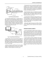
Confirm air supply pressure is same as name plate on the valve.
6.4
Check and fix any air leaking in air tubing line.
6.5
Confirm feedback linkage is connected properly.
6.6
Supply 12mA power to postioner by either using 4-20 mA external power
source or put output signal 50% from DCS.
Connect Hart communicator to positioned and go online.
6.7
From Hart menu, proceed calibration step as follow:
6.8
1. Select Hart Application
2. Select Device Set up
1HART APPLICATION
2FOUNDATION FIELD BUS
3 SETTINGS
4 LISTEN FOR PC
5 SCRATCH PAD
Online (SVI II AP)
1 Mode Normal
2 Input Signal 12.1 mA
3 Valve position
50%
4 Manual set point 0.0%
5 Read Pressure
6 Device Set up
7 Status / Diagnostics
-3-
Note
WORK STEPS
Step
Description / purpose
DEVICE SET UP
3. Select Change Mode
1 Mode
Normal
2 Change Mode
3 Set up wizard
4 Manual set up
5 Configuration
6 Calibration
7 Commissioning S..
Set mode Target
4. Select Set Up
1 Normal
2 Manual
3 Set up
1 Mode Manual
5. Select Calibration Menu
2 Change Mode
3 Set up wizard
4 Manual set up
5 Configuration
6 Calibration
7 Commissioning S..
1 Mode
Manual
6. Select Valve Travel
2 Change Mode
3 Valve Travel
4 Manual Position….
5 Valve Tuning Data
6 Sensors
7 Reset Cal Factor….
1 Mode
Manual
7. Select Find Stops
2 Change Mode
3 Find Stops
-It take about 20~30seconds
4 Open Stop Adjus…
5 Manual Stops
6 Auto Tune
7 Manual Tuning
8. Select Open Stop 1 Mode
Manual
2 Change Mode
Adjustment (If full open is 3 Find Stops
Result of check
-4-
Note
WORK STEPS
Step
Description / purpose
4 Open Stop Adjus…
more than 100% then put new 5 Manual Stops
6 Auto Tune
number as per calculation)
7Manual Tuning
- Example calculation
A: Max travel of stem
70mm
B: Scale plate
50mm
New open adjustment should be
(50/70) X 100 = 71.48%
1 Mode
Manual
9. Select Auto Tune
2 Change Mode
Stops
-Enter the Aggressiveness 34 Find
Open Stop Adjus…
5 Manual Stops
Value
6 Auto Tune
7 Manual Tuning
which is generally “0”.
- Enter Supply Pressure
10. Waiting for auto calibration
proceeding automatically. The
calibration will be completed
when message “calibration
success” appear on HART
screen.
(It takes about 3~6minutes
Result of check
-5-
Note
WORK STEPS
Step
Description / purpose
6.9
If the calibration fails, investigate and fix the root cause then try to calibrate
again.
Put back the valve into “normal” mode. Escape and disconnect HART
communicator. Put back the cover of positioner.
6.10
Result of check
Note
Result of check
Note
Check & verification
Step
Description / purpose
7.
Inform and confirm with operator about checking and testing plan
8.
Do visual integrity check, stroke test and record result on check sheet
9.
Report to DM recorded result of check/test for review and confirm
10.
If the result of check/test is acceptable, DM confirms to proceed handover to
operation. If result is not acceptable then re-work.
11.
Do housekeeping
12.
Do handover equipment to GFM. Close WO & PTW
13.
Return all material/spare part to Ware house
DM/GL acceptance:
GFM sign:
-6-
WORK STEPS
14.
Input actual WO data to CMMS
E.O.D.
-7-