Giới thiệu chuẩn truyền CAN
Bạn đang xem bản rút gọn của tài liệu. Xem và tải ngay bản đầy đủ của tài liệu tại đây (250.33 KB, 30 trang )
Page 1
Microchip Technology Inc.
Serial Communications using the dsPIC30F CAN Module
© 2005 Microchip Technology Inc. Page 1
© 2005 Microchip Technology Incorporated. All Rights Reserved. Serial Communications using the dsPIC30F CAN Module 1
DS
Digital Signal Controller
Serial Communications using
the dsPIC30F CAN Module
Microchip Technology Inc.
Welcome to the “Serial Communications using the dsPIC30F CAN Module”
web seminar.
Page 2
Microchip Technology Inc.
Serial Communications using the dsPIC30F CAN Module
© 2005 Microchip Technology Inc. Page 2
© 2005 Microchip Technology Incorporated. All Rights Reserved. Serial Communications using the dsPIC30F CAN Module 2
Session Agenda
O
CAN Protocol Overview
O
Message Reception
O
Message Transmission
O
Bit Timing
O
CAN Interrupts
In today’s session, we will start by outlining some key features of the Controller
Area Network, or CAN, module in the dsPIC30F family of devices. We will then
delve deeper into the processes of data transmission and reception through the
CAN interface, as well as bit timing considerations. Finally, we will study the
interrupt and error management mechanisms built into the CAN module.
Page 3
Microchip Technology Inc.
Serial Communications using the dsPIC30F CAN Module
© 2005 Microchip Technology Inc. Page 3
© 2005 Microchip Technology Incorporated. All Rights Reserved. Serial Communications using the dsPIC30F CAN Module 3
O
The CAN bus is a serial communication protocol
O
All nodes are connected together
O
All nodes must use the same baud rate
O
Each node can transmit or receive any message
ABS
Seat
Position
Power
Window
Engine
Control
Suspension
Outside
Mirror
Air
Conditioner
Instrument
Panel
CAN
BUS
Wheel
Transmission
Control
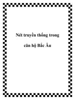
CAN Protocol Overview
Controller Area Network, or CAN, is an industry standard serial
communications protocol. The specifications for a CAN bus are described in
the International Standards Organization specification ISO-11898.
All the nodes communicating on a CAN bus are connected to a common
shared connection. Essentially, a CAN bus uses a star network topology.
Often, this shared connection is physically implemented as a two wire
differential pair for better noise immunity, thereby necessitating the use of a
CAN transceiver device in conjunction with the CAN interface on a
microcontroller.
All nodes communicating on a particular CAN bus must operate at the same
baud rate. Generally, the system designer chooses one of several standard
baud rates depending on the message latency requirements of the system.
Some typical baud rates used in CAN are 1 Mega Hertz, 500 Kilo Hertz and
125 Kilo Hertz. In a CAN bus, each node can transmit or receive any
message, which enables multicasting or broadcasting of messages as well
as in-built message arbitration.
So how does the CAN bus arbitrate and prioritize the transmission of
messages on the bus?
Page 4
Microchip Technology Inc.
Serial Communications using the dsPIC30F CAN Module
© 2005 Microchip Technology Inc. Page 4
© 2005 Microchip Technology Incorporated. All Rights Reserved. Serial Communications using the dsPIC30F CAN Module 4
O
Only one transmitter is allowed on the bus at a time
O
CAN messages contain “Identifier”and “Data
Field”
O
The transmitter sends the message to all receivers
O
All receivers will acknowledge reception of the
message
Important message
from the wheel speed sensor!
Wheel speed is 100 RPM
I got it
I got it
CAN Protocol Overview
On a CAN bus, although many nodes on the bus may have different
messages to transmit, only one transmitter is allowed to transmit at a time.
Every CAN message contains a numerical Identifier and a Data Field. In the
example depicted here, the Identifier denotes that this is an “Important
message from the wheel speed sensor”. The data field declares the wheel
speed to be 100 RPM.
This message is transmitted on the bus, and all other nodes will be able to
see it. In fact, all nodes on the bus, including the one that sent the message,
must receive the message and verify that the reception was error-free. They
must then acknowledge reception of the message, whether or not a
particular node was an intended recipient of the message.
Page 5
Microchip Technology Inc.
Serial Communications using the dsPIC30F CAN Module
© 2005 Microchip Technology Inc. Page 5
© 2005 Microchip Technology Incorporated. All Rights Reserved. Serial Communications using the dsPIC30F CAN Module 5
Start of Frame
Data
Field
8N bits (0≤N≤8)
Standard
Identifier
11 bits
4 bits
Data
Length
Code
CRC
15 bits
CRC
Field
16
Del
Ack
Field
ACK
2
Del
Control
Field
6
R0
DLC3
DLC0
R1
RTR
ID28
Arbitration
Field
32
ID18
SRR
IDE
ID17
ID0
Extended
Identifier
18 bits
7
End of
Frame
O
Identifier is at the start of the message
O
Two formats exist for the identifier: Standard and Extended
O
Data contains control and data bytes of message
O
Message has start, end, CRC and acknowledge
overhead
0 11 000 111111111
0 to 8 Bytes
of Message
Data
0-64
Identifier
Data
CAN Protocol Overview
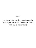
If we look at the bits transmitted in a CAN message, we can see that the
message consists of several fields.
The first bit sent is a Start of Frame bit, which indicates the beginning of a
message transmission.
This is followed by an identifier, which helps each node on the network
determine if the message is intended for it. includes the identifier bits and
some control bits. The CAN specification defines two different formats for the
identifier. The first format, called the Standard Identifier format, contains an
11 bit standard identifier or SID field and some control bits. The second
format, which is the one shown here, is called the Extended Identifier format,
and not only contains an 11 bit SID field and control bits, but also an 18 bit
Extended Identifier or EID field.
This is followed by the actual data to be transmitted. This data field is
preceded by a control field that specifies how many bytes of data are
actually present in the message, which may be length from zero to eight
bytes.
Following the data, a Cyclic Redundancy Check or CRC field is transmitted
to ensure that the message is not corrupted on the bus. This is a key
component of the Error Management mechanism of a CAN bus.
The CRC bits are followed by an Acknowledge field that allows all nodes on
the bus to acknowledge reception of the message.
Finally, there is an End of Frame sequence that demarcates the end of the
message and returns the bus to an idle state.
Page 6
Microchip Technology Inc.
Serial Communications using the dsPIC30F CAN Module
© 2005 Microchip Technology Inc. Page 6
© 2005 Microchip Technology Incorporated. All Rights Reserved. Serial Communications using the dsPIC30F CAN Module 6
O
The receivers will check the Identifier to see
if they are interested in the message
O
Checking the Identifier is done with
message filters
O
If a receiver’s filter matches the identifier, it
will store the Data Field of the message
Important message
from the wheel speed sensor!
Wheel speed is 100 RPM
I don’t care
Oh wow,
wheel speed
info!
Wheel speed
is 100 RPM
CAN Protocol Overview
Once a node receives a message, the CAN module hardware determines if
the message is of interest or not. The node then decides whether to process
or discard data.
Remember that the identifier in the message indicates the content of the
message. So the CAN module hardware inspects the identifier to see if it
matches an identifier on its user-programmed list of acceptable identifiers.
These acceptable identifiers are called Message Filters. If the identifier in the
message matches an identifier in any of the message filters, the node will
accept the message into its memory buffer. If it does not match, the received
message is discarded.
Moreover, the numerical value of the identifier inherently provides a measure
of the priority of the message. This allows the receiver to prioritize received
messages.
Point-to-point messaging is implemented by having only one node contain a
matching filter. On the other hand, multicast messages are implemented by
having all nodes contain a matching filter.
Page 7
Microchip Technology Inc.
Serial Communications using the dsPIC30F CAN Module
© 2005 Microchip Technology Inc. Page 7
© 2005 Microchip Technology Incorporated. All Rights Reserved. Serial Communications using the dsPIC30F CAN Module 7
O
Nodes must wait for a quiet bus before they
begin talking
O
What if two nodes try to transmit at the same
time?
O
The contents of the Identifier are used to
Arbitrate who will talk
Impo...
Oops, excuse me!
Critical message
from the engine!
Oil Pressure is 5 PSI
I got it
I
got it
Bus Arbitration
On a CAN bus, not only can we have multiple receivers, but there may also
be multiple transmitters. Essentially any node can send a message to any
other node. So, how does the protocol ensure that different messages do not
interfere with each other?
First, a node is not allowed to transmit until the bus is in an idle state. If a
node is transmitting a message, all other nodes must wait for that node to
finish before attempting transmission.
If multiple nodes try to transmit at the same time, the bus has a mechanism
to arbitrate which message is more important. The nodes with the less
important message will stop transmitting and the most important message
will continue transmitting the message.
Page 8
Microchip Technology Inc.
Serial Communications using the dsPIC30F CAN Module
© 2005 Microchip Technology Inc. Page 8
© 2005 Microchip Technology Incorporated. All Rights Reserved. Serial Communications using the dsPIC30F CAN Module 8
0
6
E
1
1
9
9
1
1
1
1
“Critical Message / Engine = 196”
“Important Message / Wheel Speed = 19E”
1111
1
0
0
0
0
0
0
0
0
Node
A
Node
B
0
1
Engine
Control
Wheel
Speed
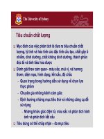
Bus Arbitration
O
Both nodes continue to transmit until mismatch
O
A zero on the bus wins over a one on the bus
O
Losing node stops transmitting, winner continues
Arbitration is only required when more than 2 nodes attempt to transmit at
the same time. As a node transmits each bit, it verifies that it sees the same
bit value on the bus that it transmitted.
As long as different transmitters are sending the same information, none of
them are aware that other nodes are also transmitting data.
In the CAN bus system, the bus is structured such that if one node is
transmitting a one and another node is transmitting a zero, the data on the
bus will be a zero.
This enables a simple arbitration mechanism. When one node, the wheel
speed in this case, transmits a one when the engine transmits a zero, the
zero from the engine wins bus arbitration. The wheel speed node will detect
that the data received on the bus did not match the data it transmitted, and
will then cease to transmit its message.
Thus, it can be inferred that identifiers with a lower numerical value have
higher priority, as they contain more zeros at the beginning of the message.
Page 9
Microchip Technology Inc.
Serial Communications using the dsPIC30F CAN Module
© 2005 Microchip Technology Inc. Page 9
© 2005 Microchip Technology Incorporated. All Rights Reserved. Serial Communications using the dsPIC30F CAN Module 9
SOF
Data
Field
End of
Frame
Arbitration
Field
Control
Field
CRC
Field
Ack
Field
CAN Message
Bit Time = 1 / Bus Rate
The bus rate defines the time for each bit
Example:
1MHz bus rate -> 1usec bit time
T
BIT
= Bit Time
Bit Timing
Let us now study the bit timing considerations of a CAN bus and see how to
set the module up for a particular bus timing selection.
The CAN bus baud rate is defined as the time required to transmit one bit in
the message. For a typical 1MHz baud rate, each bit requires 1 micro
second of time. The bit time is abbreviated as T
BIT
.
Page 10
Microchip Technology Inc.
Serial Communications using the dsPIC30F CAN Module
© 2005 Microchip Technology Inc. Page 10
© 2005 Microchip Technology Incorporated. All Rights Reserved. Serial Communications using the dsPIC30F CAN Module 10
Sample Point
SOF
Data
Field
End of
Frame
Arbitration
Field
Control
Field
CRC
Field
Ack
Field
CAN Message
Sync Prop Seg Phase Seg 1 Phase Seg 2
A CAN message bit is made up of four
segments
Bit Timing
Within each bit time, the CAN protocol specifies four time segments:
Synchronization Segment, Propagation Segment, Phase Segment 1 and
Phase Segment 2.
Page 11
Microchip Technology Inc.
Serial Communications using the dsPIC30F CAN Module
© 2005 Microchip Technology Inc. Page 11
© 2005 Microchip Technology Incorporated. All Rights Reserved. Serial Communications using the dsPIC30F CAN Module 11
O
Each Bit Timing Segment is made up of integer
units of time called Time Quanta (TQ)
O
User configures each segment to a specific
number of TQ
O
Time allocated to each segment depends on
CAN bus timing
O
Bit Time can range from 8 to 25 TQ
Sync Phase Seg 2Prop Seg Phase Seg 1
TQ TQ TQ TQ TQ TQ TQ TQ TQ
1TQ 1-8TQ 1-8TQ 1-8TQ
T
BIT
= Bit Time
Bit Timing
Each time segment is comprised of a certain number of smaller units of time
called time quanta, abbreviated as TQ.
You may wonder, what is the need for all this complexity? Well, on the CAN
bus, unlike some synchronous serial protocols such as SPI, there is no clock
signal transmitted by a node. Since there is no specific clock signal, each
node must use a digital phase locked loop to generate the clock needed by
the module. This phase locked loop is part of the module hardware, and
uses the time quantum as the basis for clock generation and
synchronization.
Each time segment is allocated an integral number of time quanta. The total
of all four segments can range from 8TQ to 25TQ, and is user-
programmable.
To learn more about how to analyze the bus timing and determine how to
allocate the TQ’s to each of the time segments, see Microchip’s web site for
application note AN754: “Understanding Microchip’s CAN Module Bit
Timing”.
Page 12
Microchip Technology Inc.
Serial Communications using the dsPIC30F CAN Module
© 2005 Microchip Technology Inc. Page 12
© 2005 Microchip Technology Incorporated. All Rights Reserved. Serial Communications using the dsPIC30F CAN Module 12
O
SJW<1:0> specifies 1-4 TQ for sync jump width
O
PRSEG<2:0> specifies 1-8 TQ for propagation segment
O
SEG1PH<2:0> specifies 1-8 TQ for phase segment 1
O
SEG2PHTS specifies options on phase segment 2
O
SEG2PH<2:0> specifies 1-8 TQ for phase segment 2
O
SAM specifies options on sampling the bus
O
The TQ time is derived from the system clock
O
BRP<5:0> bits define TQ
O
BRP = (TBIT/n * 2 * FCAN) - 1, where n=TQ clocks per bit
O
CANCKS bit in C1CTRL register selects source of FCAN
O
FCAN = FCY, if CANCKS = 1
O
FCAN = 4 * FCY, if CANCKS = 0
Bit Timing
Once the number of time quanta used in each time segment is known, they
can be used to initialize the CAN timing configuration registers, C1CFG1 and
C1CFG2.
For example:
The PRSEG bits specify the number of time quanta in the propagation
segment.
The SEG1PH bits specify the number of time quanta in phase segment one.
The SEG2PH bits specify the number of time quanta in phase segment two.
The BRP bits in the C1CFG1 register, in conjunction with the values
initialized in the C1CFG2 register, determine the CAN communication clock
period, in other words: the bit rate.
The CANCKS bit, when cleared, provides a higher resolution in configuring
the CAN bus timing, thereby allowing higher bit rates even with lower device
operating speeds.