Thyristor based FACTS Controllers for Electrical Transmission system
Bạn đang xem bản rút gọn của tài liệu. Xem và tải ngay bản đầy đủ của tài liệu tại đây (3.9 MB, 518 trang )
THYRISTOR-BASED
FACTS CONTROLLERS
FOR ELECTRICAL
TRANSMISSION SYSTEMS
R. Mohan Mathur
Ontario Power Generation
Toronto, ON, Canada
Rajiv K. Varma
Indian Institute of Technology
Kanpur, India
Mohamed E. El-Hawary, Series Editor
A JOHN WILEY & SONS, INC. PUBLICATION
This book is printed on acid-free paper. ∞
Copyright 2002 by the Institute of Electrical and Electronics Engineers, Inc. All rights
reserved.
No part of this publication may be reproduced, stored in a retrieval system or transmitted
in any form or by any means, electronic, mechanical, photocopying, recording, scanning or
otherwise, except as permitted under Sections 107 or 108 of the 1976 United States Copyright
Act, without either the prior written permission of the Publisher, or authorization through
payment of the appropriate per-copy fee to the Copyright Clearance Center, 222 Rosewood
Drive, Danvers, MA 01923, (978) 750-8400, fax (978) 750-4744. Requests to the Publisher
for permission should be addressed to the Permissions Department, John Wiley & Sons, Inc.,
605 Third Avenue, New York, NY 10158-0012, (212) 850-6011, fax (212) 850-6008, E-Mail:
PERMREQ @ WILEY.COM.
For ordering and customer service, call 1-800-CALL-WILEY.
Library of Congress Cataloging-in-Publication Data is available.
ISBN 0-471-20643-1
Printed in the United States of America
10 9 8 7 6 5 4 3 2 1
CONTENTS
1. Introduction
1.1 Background
1.2 Electrical Transmission Networks
1.3 Conventional Control Mechanisms
1.3.1 Automatic Generation Control (AGC)
1.3.2 Excitation Control
1.3.3 Transformer Tap-Changer Control
1.3.4 Phase-Shifting Transformers
1.4 Flexible ac Transmission Systems (FACTS)
1.4.1 Advances in Power-Electronics Switching Devices
1.4.2 Principles and Applications of Semiconductor
Switches
1.5 Emerging Transmission Networks
References
2. Reactive-Power Control in Electrical Power Transmission
Systems
2.1 Reactive Power
2.2 Uncompensated Transmission Lines
2.2.1 A Simple Case
2.2.1.1 Load Compensation
2.2.1.2 System Compensation
2.2.2 Lossless Distributed Parameter Lines
2.2.2.1 Symmetrical Lines
2.2.2.2 Midpoint Conditions of a Symmetrical
Line
2.2.2.3 Case Study
2.3 Passive Compensation
2.3.1 Shunt Compensation
2.3.2 Series Compensation
2.3.3 Effect on Power-Transfer Capacity
2.3.3.1 Series Compensation
2.3.3.2 Shunt Compensation
1
1
1
3
3
4
5
5
6
7
8
12
13
16
16
18
18
18
19
19
21
22
23
33
34
34
35
36
37
v
vi
CONTENTS
2.4 Summary
References
3. Principles of Conventional Reactive-Power Compensators
3.1 Introduction
3.2 Synchronous Condensers
3.2.1 Configuration
3.2.2 Applications
3.2.2.1 Control of Large-Voltage Excursions
3.2.2.2 Dynamic Reactive-Power Support at
HVDC Terminals
3.3 The Saturated Reactor (SR)
3.3.1 Configuration
3.3.2 Operating Characteristics
3.4 The Thyristor-Controlled Reactor (TCR)
3.4.1
3.4.2
3.4.3
3.4.4
3.4.5
3.4.6
3.5
3.6
3.7
3.8
The Single-Phase TCR
The 3-Phase TCR
The Thyristor-Switched Reactor (TSR)
The Segmented TCR
The 12-Pulse TCR
Operating Characteristics of a TCR
3.4.6.1 Operating Characteristics Without Voltage
Control
3.4.6.2 Operating Characteric With Voltage
Control
The Thyristor-Controlled Transformer (TCT)
The Fixed Capacitor–Thyristor-Controlled Reactor
(FC–TCR)
3.6.1 Configuration
3.6.2 Operating Characteristic
3.6.2.1 Without Step-Down Transformer
3.6.2.2 With Step-Down Transformer
The Mechanically Switched Capacitor–Thyristor-Controlled
Reactor (MSC–TCR)
The Thyristor-Switched Capacitor (TSC)
3.8.1 Switching a Capacitor to a Voltage Source
3.8.2 Switching a Series Connection of a Capacitor and
Reactor
3.8.2.1 The Term Involving Fundamental
Frequency, q 0
39
39
40
40
41
41
42
42
42
43
43
45
47
47
52
56
56
56
59
59
61
62
63
63
64
64
65
70
71
71
72
73
CONTENTS
3.8.2.2 The Terms Involving Natural Resonance
Frequency, q n
3.8.2.3 Practical Switching Strategies
3.8.3 Turning Off of the TSC Valve
3.8.4 The TSC Configuration
3.8.5 Operating Characteristic
3.9 The Thyristor-Switched Capacitor–Thyristor-Controlled
Reactor (TSC–TCR)
3.9.1 Configuration
3.9.2 Operating Characteristic
3.9.2.1 A Practical Example
3.9.3 Current Characteristic
3.9.4 Susceptance Characteristic
3.9.5 Mismatched TSC–TCR
3.10 A Comparison of Different SVCs
3.10.1 Losses
3.10.2 Performance
3.11 Summary
References
4. SVC Control Components and Models
4.1 Introduction
4.2 Measurement Systems
4.2.1 Voltage Measurement
4.2.1.1 ac/ dc Rectification
4.2.1.2 Coordinate Transformation
4.2.1.3 Fourier Analysis
4.2.1.4 Measurement of Squared Voltage
4.2.2 The Demodulation Effect of the VoltageMeasurement System
4.2.2.1 Addition
4.2.2.2 Modulation
4.2.2.3 Fourier Analysis–Based Measurement
System
4.2.2.4 Coordinate Transformation–Based
Measurement Systems
4.2.2.5 ac/ dc Rectification–Based Measurement
Systems
4.2.2.6 Filtering Requirements
4.2.3 Current Measurement
4.2.4 Power Measurement
4.2.5 The Requirements of Measurement Systems
vii
74
75
78
78
81
82
82
83
83
84
86
87
89
89
91
91
91
93
93
93
94
95
95
96
97
98
98
101
101
104
104
104
106
109
110
viii
CONTENTS
4.3
4.4
4.5
4.6
4.7
4.8
4.2.5.1 Phasor Transducers
4.2.5.2 Optical Sensors
The Voltage Regulator
4.3.1 The Basic Regulator
4.3.2 The Phase-Locked Oscillator (PLO) Voltage Regulator
4.3.2.1 The Basic Single-Phase Oscillator
4.3.2.2 The 3-Phase Oscillator
4.3.3 The Digital Implementation of the Voltage
Regulator
4.3.3.1 Digital Control
Gate-Pulse Generation
4.4.1 The Linearizing Function
4.4.2 Delays in the Firing System
4.4.2.1 Thyristor Deadtime
4.4.2.2 Thyristor Firing-Delay Time
The Synchronizing System
Additional Control and Protection Functions
4.6.1 The Damping of Electromechanical Oscillations
4.6.2 The Susceptance (Reactive-Power) Regulator
4.6.3 The Control of Neighboring Var Devices
4.6.4 Undervoltage Strategies
4.6.5 The Secondary-Overvoltage Limiter
4.6.6 The TCR Overcurrent Limiter
4.6.7 TCR Balance Control
4.6.8 The Nonlinear Gain and the Gain Supervisor
Modeling of SVC for Power-System Studies
4.7.1 Modeling for Load-Flow Studies
4.7.1.1 SVC Operation Within the Control Range
4.7.1.2 SVC Operation Outside the Control Range
4.7.2 Modeling for Small- and Large-Disturbance Studies
4.7.3 Modeling for Subsynchronous Resonance (SSR)
Studies
4.7.4 Modeling for Electromagnetic Transient Studies
4.7.5 Modeling for Harmonic-Performance Studies
Summary
References
5. Concepts of SVC Voltage Control
5.1 Introduction
5.2 Voltage Control
5.2.1 V-I Characteristics of the SVC
112
112
112
112
118
118
120
121
122
123
124
125
125
126
127
128
128
129
131
132
132
133
133
133
134
134
134
135
136
137
137
137
138
138
142
142
142
142
CONTENTS
5.2.1.1 Dynamic Characteristics
5.2.1.2 Steady-State Characteristic
5.2.2 Voltage Control by the SVC
5.2.3 Advantages of the Slope in the SVC Dynamic
Characteristic
5.2.3.1 Reduction of the SVC Rating
5.2.3.2 Prevention of Frequency Operation at
Reactive-Power Limits
5.2.3.3 Load Sharing Between Parallel-Connected
SVCs
5.2.4 Influence of the SVC on System Voltage
5.2.4.1 Coupling Transformer Ignored
5.2.4.2 Coupling Transformer Considered
5.2.4.3 The System Gain
5.2.5 Design of the SVC Voltage Regulator
5.2.5.1 Simplistic Design Based on System Gain
5.2.5.2 Design That Considers Generator
Dynamics
5.3 Effect of Network Resonances on the Controller Response
5.3.1 Critical Power-System Parameters
5.3.2 Sensitivity to Power-System Parameters
5.3.2.1 Response Variation With RegulatorTransient Gain, K T
5.3.2.2 Response Variation With System Strength,
ESCR0
5.3.2.3 Voltage-Sensitivity Transfer Function
5.3.3 Sensitivity to TCR Operating Point
5.3.4 Choice of Transient Gain
5.3.5 Certain Features of the SVC Response
5.3.6 Methods for Improving the Voltage-Controller
Response
5.3.6.1 Manual Gain Switching
5.3.6.2 The Nonlinear Gain
5.3.6.3 Bang-Bang Control
5.3.6.4 The Gain Supervisor
5.3.6.5 Series-Dynamic Compensation
5.3.6.6 ac-Side Control Filters
5.4 The 2nd Harmonic Interaction Between the SVC and
ac Network
5.4.1 Influence of the 2nd Harmonic Voltage on the TCR
5.4.2 Causes of 2nd Harmonic Distortion
5.4.2.1 Fault Clearing
ix
142
145
145
147
147
148
148
149
149
151
152
154
155
163
163
166
166
170
170
170
172
175
176
177
177
177
178
178
180
183
186
186
191
191
x
CONTENTS
5.5
5.6
5.7
5.8
5.4.2.2 Reactor/ Transformer Switching Near an
SVC
5.4.2.3 Geomagnetically Induced Currents
5.4.2.4 Noise or Imbalance in the Control
Systems
5.4.3 TCR Balance Control
Application of the SVC to Series-Compensated ac Systems
5.5.1 ac System–Resonant Modes
5.5.1.1 Shunt-Capacitance Resonance
5.5.1.2 Series-Line Resonance
5.5.1.3 Shunt-Reactor Resonance
5.5.2 SVC Transient Response With Series-Compensated
ac-Transmission Lines
5.5.2.1 Reactor Switching
5.5.2.2 Fault Application and Clearing
5.5.3 Effect of the Shunt-Reactor Mode on the SVC
Voltage Controller
5.5.3.1 Effect of the TCR Operating Point
5.5.3.2 Filtering of the Shunt-Resonant Mode
3rd Harmonic Distortion
Voltage-Controller Design Studies
5.7.1 Modeling Aspects
5.7.2 Special Performance-Evaluation Studies
5.7.3 Study Methodologies for Controller Design
5.7.3.1 Impedance-Versus-Frequency Computation
5.7.3.2 Eigenvalue Analyses
5.7.3.3 Simulation Studies
Summary
References
6. SVC Applications
6.1 Introduction
6.2 Increase in Steady-State Power-Transfer Capacity
6.3 Enhancement of Transient Stability
6.3.1 Power-Angle Curves
6.3.2 Synchronizing Torque
6.3.2.1 Uncompensated System
6.3.2.2 SVC-Compensated System
6.3.3 Modulation of the SVC Bus Voltage
6.4 Augmentation of Power-System Damping
6.4.1 Principle of the SVC Auxiliary Control
193
195
195
195
199
199
199
201
201
203
204
207
209
211
211
214
217
217
217
217
217
218
218
218
218
221
221
221
224
225
226
227
228
229
232
233
CONTENTS
6.4.2 Torque Contributions of SVC Controllers
6.4.2.1 Effect of the Power System
6.4.2.2 Effect of the SVC
6.4.3 Design of an SVC PSDC
6.4.3.1 Controllability
6.4.3.2 Influence of SVC Sites and the Nature of
Loads
6.4.3.3 Selection Criteria for PSDC Input Signals
6.4.3.4 Input Filtering
6.4.3.5 General Characteristics of PSDC Input
Signals
6.4.3.6 Performance of PSDC Input Signals
6.4.3.7 SVC PSDC Requirements
6.4.3.8 Design Procedure for a PSDC
6.4.3.9 Case Study
6.4.4 Composite Signals for Damping Control
6.4.4.1 Frequency of Remotely Synthesized
Voltage
6.4.4.2 Case Study
6.4.5 Alternative Techniques for the Design of SVC
Auxiliary Controllers
6.5 SVC Mitigation of Subsynchronous Resonance (SSR)
6.5.1 Principle of SVC Control
6.5.2 Configuration and Design of the SVC Controller
6.5.3 Rating of an SVC
6.6 Prevention of Voltage Instability
6.6.1 Principles of SVC Control
6.6.1.1 A Case Study
6.6.2 Configuration and Design of the SVC Controller
6.6.3 Rating of an SVC
6.7 Improvement of HVDC Link Performance
6.7.1 Principles and Applications of SVC Control
6.7.1.1 Voltage Regulation
6.7.1.2 Suppression of Temporary Overvoltages
6.7.1.3 Support During Recovery From Large
Disturbances
6.7.2 Configuration and Design of the SVC Controller
6.7.2.1 Interactions Between the SVC and the
HVDC
6.7.3 Rating of the SVC
xi
235
235
236
239
240
240
242
243
243
244
245
248
249
252
252
254
256
257
257
260
262
263
263
263
265
266
268
269
269
269
269
271
272
272
xii
CONTENTS
6.8 Summary
References
7. The Thyristor-Controlled Series Capacitor (TCSC)
7.1 Series Compensation
7.1.1 Fixed-Series Compensation
7.1.2 The Need for Variable-Series Compensation
7.1.3 Advantages of the TCSC
7.2 The TCSC Controller
7.3 Operation of the TCSC
7.3.1 Basic Principle
7.3.2 Modes of TCSC Operation
7.3.2.1 Bypassed-Thyristor Mode
7.3.2.2 Blocked-Thyristor Mode
7.3.2.3 Partially Conducting Thyristor, or Vernier,
Mode
7.4 The TSSC
7.5 Analysis of the TCSC
7.6 Capability Characteristics
7.6.1 The Single-Module TCSC
7.6.2 The Multimodule TCSC
7.7 Harmonic Performance
7.8 Losses
7.9 Response of the TCSC
7.10 Modeling of the TCSC
7.10.1 Variable-Reactance Model
7.10.1.1 Transient-Stability Model
7.10.1.2 Long-Term-Stability Model
7.10.2 An Advanced Transient-Stability Studies Model
7.10.2.1 TCSC Controller Optimization and TCSC
Response-Time Compensation
7.10.3 Discrete and Phasor Models
7.10.4 Modeling for Subsynchronous Resonance (SSR)
Studies
7.11 Summary
References
8. TCSC Applications
8.1 Introduction
8.2 Open-Loop Control
8.3 Closed-Loop Control
272
272
277
277
277
277
278
279
280
280
281
282
283
283
284
285
290
292
294
295
298
301
304
304
305
308
309
310
311
311
312
313
315
315
315
316
CONTENTS
8.4
8.5
8.6
8.7
8.8
8.9
8.3.1 Constant-Current (CC) Control
8.3.2 Constant-Angle (CA) Control
8.3.3 Enhanced Current Control
8.3.4 Constant-Power Control
8.3.5 Enhanced Power Control
8.3.6 Firing Schemes and Synchronization
Improvement of the System-Stability Limit
Enhancement of System Damping
8.5.1 Principle of Damping
8.5.2 Bang-Bang Control
8.5.3 Auxiliary Signals for TCSC Modulation
8.5.3.1 Local Signals
8.5.3.2 Remote Signals
8.5.4 Case Study for Multimodal Decomposition–Based
PSDC Design
8.5.4.1 Selection of the Measurement Signal
8.5.4.2 Selection of the Synthesizing Impedance
8.5.5 H ∞ Method–Based PSDC Design
8.5.6 Alternative Techniques for PSDC Design
8.5.7 Placement of the TCSC
Subsynchronous Resonance (SSR) Mitigation
8.6.1 TCSC Impedance at Subsynchronous Frequencies
8.6.2 A Case Study
8.6.2.1 Transient-Torque Minimization
8.6.2.2 Criteria for SSR Mitigation by the TCSC
Voltage-Collapse Prevention
TCSC Installations
8.8.1 Imperatriz–Serra da Mesa TCSCs in Brazil
8.8.1.1 TCSC Power-Oscillation Damping (POD)
Control
8.8.1.2 Phasor Estimation
8.8.1.3 Performance of Both TCSCs
8.8.2 Stode TCSC in Sweden
Summary
References
9. Coordination of FACTS Controllers
9.1 Introduction
9.2 Controller Interactions
9.2.1 Steady-State Interactions
9.2.2 Electromechanical-Oscillation Interactions
9.2.3 Control or Small-Signal Oscillations
xiii
316
317
319
319
320
321
321
322
323
325
325
325
325
326
326
327
330
334
334
334
335
340
342
342
343
345
346
348
350
352
353
355
355
359
359
359
360
360
361
xiv
CONTENTS
9.3
9.4
9.5
9.6
9.7
9.8
9.2.4 Subsynchronous Resonance (SSR) Interactions
9.2.5 High-Frequency Interactions
9.2.6 The Frequency Response of FACTS Controllers
9.2.6.1 The Frequency Response of the SVC
9.2.6.2 The Frequency Response of the TCSC
SVC–SVC Interaction
9.3.1 The Effect of Electrical Coupling and Short-Circuit
Levels
9.3.1.1 Uncoupled SVC Buses
9.3.1.2 Coupled SVC Buses
9.3.2 The System Without Series Compensation
9.3.3 The System With Series Compensation
9.3.3.1 Shunt-Reactor Resonance
9.3.4 High-Frequency Interactions
9.3.5 Additional Coordination Features
9.3.5.1 Parallel SVCs
9.3.5.2 Electrically Close SVCs
SVC–HVDC Interaction
SVC–TCSC Interaction
9.5.1 Input Signal of the TCSC–PSDC With Bus
Voltage
9.5.2 Input Signal of the TCSC–PSDC With a System
Angle
9.5.3 High-Frequency Interactions
TCSC–TCSC Interaction
9.6.1 The Effect of Loop Impedance
9.6.1.1 Low-Loop Impedance
9.6.1.2 High-Loop Impedance
9.6.2 High-Frequency Interaction
Performance Criteria for Damping-Controller Design
Coordination of Multiple Controllers Using Linear-Control
Techniques
9.8.1 The Basic Procedure for Controller Design
9.8.1.1 Derivation of the System Model
9.8.1.2 Enumeration of the System Performance
Specifications
9.8.1.3 Selection of the Measurement and Control
Signals
9.8.1.4 Controller Design and Coordination
9.8.1.5 Validation of the Design and Performance
Evaluation
9.8.2 Controller Coordination for Damping Enhancement
361
361
362
362
364
364
364
364
365
366
371
373
374
379
379
380
381
382
384
387
387
393
393
393
394
394
399
401
401
401
402
402
402
403
403
CONTENTS
9.8.3 Linear Quadratic Regulator (LQR)–Based
Technique
9.8.4 Constrained Optimization
9.8.4.1 Techniques Without Explicit Robustness
Criteria
9.8.4.2 Techniques With Explicit Robustness
Criteria
9.8.5 Nonlinear-Constrained Optimization of a SelectiveModel-Performance Index
9.8.6 Global Coordination Using Nonlinear-Constrained
Optimization
9.8.7 Control Coordination Using Genetic Algorithms
9.9 Coordination of Multiple Controllers Using NonlinearControl Techniques
9.10 Summary
References
10. Emerging FACTS Controllers
10.1 Introduction
10.2 The STATCOM
10.2.1 The Principle of Operation
10.2.2 The V-I Characteristic
10.2.3 Harmonic Performance
10.2.4 Steady-State Model
10.2.5 SSR Mitigation
10.2.5.1 A Study System
10.2.5.2 STATCOM Performance
10.2.6 Dynamic Compensation
10.2.6.1 A Multilevel VSC–Based STATCOM
10.2.6.2 A Selective Harmonic-Elimination
Modulation (SHEM) Technique
10.2.6.3 Capacitor-Voltage Control
10.2.6.4 STATCOM Performance
10.3 The SSSC
10.3.1 The Principle of Operation
10.3.2 The Control System
10.3.3 Applications
10.3.3.1 Power-Flow Control
10.3.3.2 SSR Mitigation
10.4 The UPFC
10.4.1 The Principle of Operation
10.4.2 Applications
xv
405
405
405
405
405
407
408
409
409
410
413
413
413
415
417
419
421
425
425
426
428
428
431
431
433
437
437
440
442
442
443
444
444
448
xvi
CONTENTS
10.5 Comparative Evaluation of Different FACTS Controllers
10.5.1 Performance Comparison
10.5.2 Cost Comparison
10.6 Future Direction of FACTS Technology
10.6.1 The Role of Communications
10.6.2 Control-Design Issues
10.7 Summary
References
Appendix A. Design of an SVC Voltage Regulator
A.1 Study System
A.2 Method of System Gain
A.3 Eigenvalue Analysis
A.3.1 Step Response
A.3.2 Power-Transfer Studies
A.4 Simulator Studies
A.4.1 Step-Response Studies
A.4.2 Power-Transfer Limits
A.5 A Comparison of Physical Simulator Results
With Analytical and Digital Simulator Results
Using Linearized Models
References
449
450
452
453
455
455
456
457
462
462
464
465
466
471
472
472
474
475
477
Appendix B. Transient-Stability Enhancement in a Midpoint
SVC-Compensated SMIB System
478
Appendix C. Approximate Multimodal Decomposition Method
for the Design of FACTS Controllers
481
C.1 Introduction
C.2 Modal Analysis of the ith Swing Mode, l i
C.2.1 Effect of the Damping Controller
C.3 Implications of Different Transfer Functions
C.3.1 Controllability
C.3.2 Observability
C.3.3 The Inner Loop
C.4 Design of the Damping Controller
C.4.1 The Controller-Phase Index (CPI)
C.4.2 The Maximum Damping Influence (MDI)
Index
C.4.3 The Natural Phase Influence (NPI) Index
References
481
483
485
486
486
486
486
486
487
487
488
489
CONTENTS
Appendix D. FACTS Terms and Definitions
D.1 Definitions of Basic Terms
D.2 Definitions of Facts Controller Terms
Reference
Index
xvii
490
490
490
492
493
CHAPTER 1
Introduction
1.1
BACKGROUND
This chapter briefly discusses the growth of complex electrical power networks.
It introduces the lack of controllability of the active- and reactive-power flows
in energized networks. (These flows tend to diffuse in the network, depending primarily on the impedance of power lines.) This chapter also describes the
conventional controlled systems, such as automatic governor control and excitation control employed at generating stations. Transformer tap-changer control
is another control feature generally available in transmission networks. Arising from the transformer combinations and the use of on-load tap changers,
phase-shifting transformers are realized, which are primarily used to mitigate
circulating power on network tie-lines.
This introduction and the recognition of limited controllability provide
the basis for introducing the concept of the flexible ac transmission system
(FACTS). Since newly developed FACTS devices rely on the advances made
in semiconductor components and the resulting power-electronic devices, these,
too, are introduced.
This chapter also introduces the basic operating principles of new FACTS
devices. (These principles are fully discussed in later chapters of this book.)
Finally, the chapter presents a brief commentary on emerging deregulation,
competition, and open access in power utilities. In that context, the value of
FACTS devices for emerging transmission companies is identified.
1.2
ELECTRICAL TRANSMISSION NETWORKS
The rapid growth in electrical energy use, combined with the demand for lowcost energy, has gradually led to the development of generation sites remotely
located from the load centers. In particular, the remote generating stations
include hydroelectric stations, which exploit sites with higher heads and significant water flows; fossil fuel stations, located close to coal mines; geothermal
stations and tidal-power plants, which are sitebound; and, sometimes, nuclear
power plants purposely built distant from urban centers. The generation of bulk
1
2
INTRODUCTION
power at remote locations necessitates the use of transmission lines to connect
generation sites to load centers. Furthermore, to enhance system reliability, multiple lines that connect load centers to several sources, interlink neighboring
utilities, and build the needed levels of redundancy have gradually led to the
evolution of complex interconnected electrical transmission networks. These
networks now exist on all continents.
An electrical power transmission network comprises mostly 3-phase
alternating-current (ac) transmission lines operating at different transmission
voltages (generally at 230 kV and higher). With increasing requirement of
power-transmission capacity and/ or longer transmission distances, the transmission voltages continue to increase; indeed, increases in transmission voltages are linked closely to decreasing transmission losses. Transmission voltages
have gradually increased to 765 kV in North America, with power transmission
reaching 1500 MVA on a line limited largely by the risk that a power utility
may be willing to accept because of losing a line.
An ac power transmission network comprises 3-phase overhead lines, which,
although cheaper to build and maintain, require expensive right-of-ways. However, in densely populated areas where right-of-ways incur a premium price,
underground cable transmission is used. Increasing pressures arising from ecological and aesthetic considerations, as well as improved reliability, favor underground transmission for future expansion.
In a complex interconnected ac transmission network, the source-to-a-load
power flow finds multiple transmission paths. For a system comprising multiple
sources and numerous loads, a load-flow study must be performed to determine
the levels of active- and reactive-power flows on all lines. Its impedance and
the voltages at its terminals determine the flow of active and reactive powers
on a line. The result is that whereas interconnected ac transmission networks
provide reliability of power supply, no control exists on line loading except to
modify them by changing line impedances by adding series and/ or shunt-circuit
elements (capacitors and reactors).
The long-distance separation of a generating station from a load center
requiring long transmission lines of high capacity and, in some cases in which
a transmission line must cross a body of water, the use of ac/ dc and dc/ ac
converters at the terminals of an HVDC line, became a viable alternative many
years ago. Consequently, beginning in 1954, HVDC transmission has grown
steadily to the current ±600 kV lines with about 4000 A capacity. Also, direct
current (dc) transmission networks, including multiterminal configurations, are
already embedded in ac transmission networks. The most significant feature of
an HVDC transmission network is its full controllability with respect to power
transmission [1]–[5].
Until recently, active- and reactive-power control in ac transmission networks
was exercised by carefully adjusting transmission line impedances, as well as
regulating terminal voltages by generator excitation control and by transformer
tap changers. At times, series and shunt impedances were employed to effectively change line impedances.
CONVENTIONAL CONTROL MECHANISMS
1.3
3
CONVENTIONAL CONTROL MECHANISMS
In the foregoing discussion, a lack of control on active- and reactive-power flow
on a given line, embedded in an interconnected ac transmission network, was
stated. Also, to maintain steady-state voltages and, in selected cases, to alter
the power-transmission capacity of lines, traditional use of shunt and series
impedances was hinted.
In a conventional ac power system, however, most of the controllability
exists at generating stations. For example, generators called spinning reserves
maintain an instantaneous balance between power demand and power supply.
These generators, in fact, are purposely operated at reduced power. Also, to regulate the system frequency and for maintaining the system at the rated voltage,
controls are exercised on selected generators.
1.3.1
Automatic Generation Control (AGC)
The megawatt (MW) output of a generator is regulated by controlling the driving torque, T m , provided by a prime-mover turbine. In a conventional electromechanical system, it could be a steam or a hydraulic turbine. The needed
change in the turbine-output torque is achieved by controlling the steam/ water
input into the turbine. Therefore, in situations where the output exceeds or falls
below the input, a speed-governing system senses the deviation in the generator
speed because of the load-generation mismatch, adjusts the mechanical driving
torque to restore the power balance, and returns the operating speed to its rated
value. The speed-governor output is invariably taken through several stages of
mechanical amplification for controlling the inlet (steam/ water) valve/ gate of
the driving turbine. Figure 1.1 shows the basic speed-governing system of a
generator supplying an isolated load. The operation of this basic feedback-control system is enhanced by adding further control inputs to help control the
frequency of a large interconnection. In that role, the control system becomes
an automatic generation control (AGC) with supplementary signals.
Valve / Gate
Tm
Pm
Turbine
Steam/Water
G
Active Power,
Pe
Te Generator
Speed-Governor
Electrical
Load, PL
where
Tm = the mechanical driving torque
Te = the mechanical load torque from the generator electrical output
Pm = the mechanical power input to the generator
Figure 1.1
A speed-governor system.
4
INTRODUCTION
∆f (s)
1
R
−K i
s +
∆PL
−
Σ
Governor
GH
Turbine
GT
∆PT 1(s)
+
∆PT 2(s)
−
Σ
+
Power
System
∆f (s)
Second Generating Unit
Figure 1.2
An AGC with supplementary control on the principal generating unit.
To avoid competing control actions, in a multigenerator unit station each
speed-governor system is provided with droop (R) characteristics through a proportional feedback loop (R, Hz/ MW). Figure 1.2 shows an AGC on the principal generating unit with supplementary control. In contrast, the second, third,
and remaining generating units in a multiunit station operate with their basic
AGCs. In a complex interconnected system, the supplementary control signal
may be determined by a load-dispatch center.
1.3.2
Excitation Control
The basic function of an exciter is to provide a dc source for field excitation
of a synchronous generator. A control on exciter voltage results in controlling the field current, which, in turn, controls the generated voltage. When a
synchronous generator is connected to a large system where the operating frequency and the terminal voltages are largely unaffected by a generator, its excitation control causes its reactive power output to change.
In older power plants, a dc generator, also called an exciter, was mounted
on the main generator shaft. A control of the field excitation of the dc generator provided a controlled excitation source for the main generator. In contrast,
modern stations employ either a brushless exciter (an inverted 3-phase alternator with a solid-state rectifier connecting the resulting dc source directly through
the shaft to the field windings of the main generator) or a static exciter (the use
of a station supply with static rectifiers).
An excitation-control system employs a voltage controller to control
the excitation voltage. This operation is typically recognized as an automatic voltage regulator (AVR). However, because an excitation control
operates quickly, several stabilizing and protective signals are invariably
added to the basic voltage regulator. A power-system stabilizer (PSS) is
implemented by adding auxiliary damping signals derived from the shaft
speed, or the terminal frequency, or the power—an effective and frequently used technique for enhancing small-signal stability of the connected system. Figure 1.3 shows the functionality of an excitation-control
system.
CONVENTIONAL CONTROL MECHANISMS
5
Limiters and
Protective Circuits
Regulator
Exciter
Generator
System
Power System
Stabilizer
Limiters and
Protective Circuits
Figure 1.3
1.3.3
A conceptual block diagram of a modern excitation controller.
Transformer Tap-Changer Control
Next to the generating units, transformers constitute the second family of major
power-transmission-system apparatuses. In addition to increasing and decreasing nominal voltages, many transformers are equipped with tap-changers to
realize a limited range of voltage control. This tap control can be carried out
manually or automatically. Two types of tap changers are usually available: offload tap changers, which perform adjustments when deenergized, and on-load
tap changers, which are equipped with current-commutation capacity and are
operated under load. Tap changers may be provided on one of the two transformer windings as well as on autotransformers.
Because tap-changing transformers vary voltages and, therefore, the reactivepower flow, these transformers may be used as reactive-power-control devices.
On-load tap-changing transformers are usually employed to correct voltage profiles on an hourly or daily basis to accommodate load variations. Their speed
of operation is generally slow, and frequent operations result in electrical and
mechanical wear and tear.
1.3.4
Phase-Shifting Transformers
A special form of a 3-phase–regulating transformer is realized by combining
a transformer that is connected in series with a line to a voltage transformer
equipped with a tap changer. The windings of the voltage transformer are so connected that on its secondary side, phase-quadrature voltages are generated and
fed into the secondary windings of the series transformer. Thus the addition of
small, phase-quadrature voltage components to the phase voltages of the line creates phase-shifted output voltages without any appreciable change in magnitude.
A phase-shifting transformer is therefore able to introduce a phase shift in a line.
Figure 1.4 shows such an arrangement together with a phasor diagram. The
phasor diagram shows the phase shift realized without an appreciable change in
magnitude by the injection of phase-quadrature voltage components in a 3-phase
6
INTRODUCTION
∆Vbc
V∠v
Va
∆Vbc
Vb
∆Vca
∆Vab
Vc
A
Va′
Vb′
Va
Va′
∆v
V ′∠v + ∆ v
Vb′
Vc′
∆Vca
Vc
C
B
∆Vab
(a)
Figure 1.4
diagram.
Vb
Vc′
(b)
A phase-shifting transformer: (a) a schematic diagram and (b) a phasor
system. When a phase-shifting transformer employs an on-load tap changer,
controllable phase-shifting is achieved. The interesting aspect of such phase
shifters is that despite their low MVA capacity, by controlling the phase shift
they exercise a significant real-power control. Therefore, they are used to mitigate circulating power flows in interconnected utilities. A promising application of these devices is in creating active-power regulation on selected lines and
securing active-power damping through the incorporation of auxiliary signals
in their feedback controllers. From this description, it is easy to visualize that
an incremental in-phase component can also be added in lines to alter only their
voltage magnitudes, not their phase.
The modification of voltage magnitudes and/ or their phase by adding
a control voltage is an important concept. It forms the basis of some of
the new FACTS devices discussed in this book. The injected voltage need
not be realized through electromagnetic transformer–winding arrangements;
instead, by using high-speed semiconductor switches such as gate turn-off
(GTO) thyristors, voltage source inverters (VSIs)—synchronized with the system frequency—are produced. The application of a VSI to compensate the linevoltage drop yields a new, fast, controllable reactive-power compensator: the
static synchronous series compensator (SSSC). The application of a VSI to
inject a phase-quadrature voltage in lines yields a new, fast, controllable phase
shifter for active- power control. Once a synchronized VSI is produced, it is
indeed easy to regulate both the magnitude and the phase angle of the injected
voltages to yield a new, unified power-flow controller (UPFC).
1.4
FLEXIBLE AC TRANSMISSION SYSTEM (FACTS)
The FACTS is a concept based on power-electronic controllers, which enhance
the value of transmission networks by increasing the use of their capacity.
FLEXIBLE AC TRANSMISSION SYSTEM (FACTS)
7
[6]–[15]. As these controllers operate very fast, they enlarge the safe operating
limits of a transmission system without risking stability. Needless to say, the era of
the FACTS was triggered by the development of new solid-state electrical switching devices. Gradually, the use of the FACTS has given rise to new controllable
systems. It is these systems that form the subject matter of this book.
Today, it is expected that within the operating constraints of the current-carrying thermal limits of conductors, the voltage limits of electrical insulating devices,
and the structural limits of the supporting infrastructure, an operator should be
able to control power flows on lines to secure the highest safety margin as well
as transmit electrical power at a minimum of operating cost. Doing so constitutes
the increased value of transmission assets.
The search for enhanced controllability of power on ac transmission networks
was initiated by newly acquired current and power controllability in HVDC transmission. Replacement of mercury-arc valves by thyristors yielded robust ac/ dc
converters, minimized conversion losses, and yielded fast control on transmitted
power—so much so that line-to-ground fault clearing became possible without
the use of circuit breakers. Instead, by rapidly attaining current zero through the
use of current controllers and, in addition, by rapidly recovering the electromagnetic energy stored in the energized line, the faulted dc line could be isolated by
low interruption–rating isolators.
The very fast power controllability in HVDC systems made them candidates for special applications in back-to-back configurations to control the power
exchange between the networks they linked. The rapid control of power led to the
added use of HVDC links for enhancing transient stability of connected systems
through active-power damping. The enhancement in stability was accomplished
by adding auxiliary signals in the current controllers of the converters [16], [17].
1.4.1
Advances in Power-Electronics Switching Devices
As mentioned previously, the full potential of ac/ dc converter technology was
better realized once mercury-arc valves were replaced by solid-state switching devices called thyristors. Thyristors offered controlled turn-on of currents
but not their interruption. The rapid growth in thyristor voltage and current
ratings accelerated their application, and the inclusion of internal light triggering simplified the converter controls and their configurations even more. Most
applications, however, were based on the natural commutation of currents. In
special cases where forced commutation was required, elaborate circuitry using
discharging capacitors to create temporary current zeroes were employed.
Thyristors are now available in large sizes, eliminating the need for paralleling them for high-current applications. Their voltage ratings have also increased
so that relatively few are required to be connected in series to yield switches
or converters for power-transmission applications. Actually, the present trend
is to produce high-power electronic building blocks (HPEBBs) to configure
high-power switches and converters, thus eliminating the custom-design needs
8
INTRODUCTION
at the device level. Availability of HPEBBs should accelerate development of
new FACTS devices. The HPEBB thyristors are available in compact packaging and in sufficiently large sizes (e.g., 125-mm thyristors: 5.5 kV, 4 kA or
4.5 kV, 5.8 kA) for most applications. For switching applications, such as that
for tap changers or static phase shifters, anti-parallel–connected thyristor modules, complete with snubber circuits, are available. These switches provide sufficiently high transient-current capacity to endure fault currents.
The GTO semiconductor devices facilitate current turn-on as well as turnoff by using control signals. This technology has grown very rapidly; consequently, high-power GTOs are now available (100 mm, 6 kV or 150 mm, 9
kV). Full on–off control offered by GTOs has made pulse width–modulated
(PWM) inverters easy to realize [18].
Advances in semiconductor technology are yielding new efficient, simpleto-operate devices. The insulated gate bipolar transistor (IGBT) and the metaloxide semiconductor (MOS)–controlled thyristor (MCT) control electric power
using low levels of energy from their high-impedance MOS gates, as compared
to high-current pulses needed for thyristors or GTOs. Unfortunately, the available voltage ratings of these devices are still limited.
The MOS turn-off (MTO) thyristor combines the advantages of both thyristors and MOS devices by using a current-controlled turn-on (thyristor) and
a voltage-controlled turn-off having a high-impedance MOS structure [19].
Hybrid MTOs are being proposed that show substantially low device losses
relative to GTOs. Because MTOs use nearly half the parts of GTOs, their application promises significant reliability improvement.
The availability of new and significantly improved switching devices in convenient packages (HPEBB) will aid the development of new, more versatile
FACTS devices. The symbolic representation and equivalent circuits of a thyristor, GTO, and MCT are shown in Fig. 1.5.
1.4.2
Principles and Applications of Semiconductor Switches
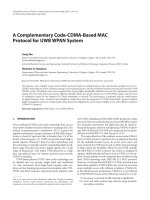
In high-power applications, semiconductor devices are used primarily as
switches. To accommodate switching in an ac system, two unidirectional conducting devices are connected in an antiparallel configuration, as shown in Fig.
1.6. Such a switch may be employed per phase to connect or disconnect a
shunt-circuit element, such as a capacitor or reactor, or to short-circuit a seriesconnected–circuit element, such as a capacitor. A reverse-biased thyristor automatically turns off at current zero, for which reason an antiparallel thyristor
connection is used to control the current through a reactor by delaying its turnon instant, as shown in Fig. 1.6(b). It is easy to see that the current through a
connected reactor may be controlled from full value to zero by adjusting the
delay angle, a, of the gate’s firing signal from 90 to 180 .
Thus a thyristor switch offers current control in a reactor, rendering it a controlled reactor. However, because a capacitor current leads the applied voltage
by approximately 90 , the capacitor switching always causes transient in-rush
FLEXIBLE AC TRANSMISSION SYSTEM (FACTS)
G , Gate
9
C , Cathode
A
N2
G
P2
N1
C
G
P1
C
Equivalent Circuit
A
Symbol
A , Anode
(a)
A , Anode
P
1
G
C
N
N+
2
N
3
P
N+
N+
A
Symbol
G , Gate
C , Cathode
(b)
A , Anode
C
G
G , Gate
A
Symbol
C , Cathode
(c)
Figure 1.5 Semiconductor switching devices for power-electronics applications: (a)
a thyristor (silicon-controlled rectifier); (b) a gate turn-off (GTO) thyristor; and (c) a
P-MCT equivalent circuit.
10
INTRODUCTION
Va
Va
ia
ia
a
Delay
G1
G1
G2
G2
(b)
(a)
Figure 1.6 A thyristor switch for ac applications: (a) a switch and (b) a controlled
reactor current.
currents that must be minimized by switching charged capacitors at instants
when the voltage across the switch is near zero. Therefore, a thyristor switch is
used only to turn on or turn off a capacitor, thereby implementing a switched
capacitor.
Parallel combination of switched capacitors and controlled reactors provides
a smooth current-control range from capacitive to inductive values by switching
the capacitor and controlling the current in the reactor. Shunt combinations of
thyristor-controlled reactors (TCRs) and thyristor-switched capacitors (TSCs)
yield static var compensators (SVCs), which are described in detail in Chapters
3–6.
Thyristor switches may be used for shorting capacitors; hence they find application in step changes of series compensation of transmission lines. A blocked
thyristor switch connected across a series capacitor introduces the capacitor in
line, whereas a fully conducting thyristor switch removes it. In reality, this step
control can be smoothed by connecting an appropriately dimensioned reactor
in series with the thyristor switch—as shown in Fig. 1.7—to yield vernier con-
⇓
Equivalent
Figure 1.7
A thyristor-controlled series capacitor (TCSC).