Assessment of causes for partial settlement of gidabo dam, southern ethiopia
Bạn đang xem bản rút gọn của tài liệu. Xem và tải ngay bản đầy đủ của tài liệu tại đây (8.03 MB, 90 trang )
Assessment of Causes for Partial settlement
of Gidabo Dam, Southern Ethiopia.
Ataklti Hagos
A Thesis Submitted to
School of Earth Sciences
Presented In Partial Fulfillment of Requirement for the Degree of Masters of
Science (in Geology Engineering)
ADDIS ABABA UNIVERSITY
Addis Ababa, Ethiopia
June, 2017
Assessment of causes for partial settlement
of Gidabo Dam, Southern Ethiopia.
Ataklti Hagos
A Thesis Submitted to
Scholl of Erath Sciences
Presented In Partial Fulfillment of Requirement for the Degree of Masters of
Science (in Geology Engineering)
ADDIS ABABA UNIVERSITY
Addis Ababa, Ethiopia
June, 2017
DECLARATION
I hereby declare that this thesis is my original work that has been carried out under the
supervision of Dr. Tarun Tarun Kumar Raghuvanshi, School of Earth science, Addis
Ababa University during the year 2017 as part of the Master of Science program in
Engineering Geology in accordance with the rule and regulation of the institute. I further
declare that this work has not been submitted to any other university of institution for the
award of any degree or diploma and all sources of materials used for the thesis have duly
acknowledged.
Ataklti Hagos
Signature
Place and date of submission: School of Graduate Studies, Addis Ababa University
May 2017
ABSTRACT
ABSTRACT
Assessment of causes for partial settlement of Gidabo Dam, Southern Ethiopia.
Ataklti Hagos
Addis Ababa University, 2017
The present study was carried out at Gidabo Dam, which is proposed on Gidabo River in
Oromia Regional State, about 375 km from Addis Ababa, the capital city of Ethiopia. Gidabo
Dam has faced settlement at the conduit outlet foundation during the construction time which
was measured to be about 0.4 m. The main objectives of this study were to assess the possible
causes of partial settlement and to estimate the amount of potential future settlement of the
dam. The general methodology followed for the present study was based on thorough
literature review, field investigations and data collection, analysis and evaluation of various
soil parameters of settlement. For the present study immediate and primary settlement
analysis was carried out. Elastic theory for cohesive soils, Janbu’s approach and one
dimensional settlement analysis were applied to estimate the settlement amount of the upper
part of backfill foundation unit and compressible silty clay layer of the dam foundation. For
the granular soil foundation at the bottom immediate settlement was estimated from in-situ
standard penetration test (SPT) results.
The present study results showed excessive settlement. The estimated settlement is more than
the expected settlement as anticipated in the design of the dam. The differential settlement is
also expected at the contact of the backfill material, at outlet conduit and in between the
intake tower and the outlet conduit. As investigated in the present study, the primary causes
of the settlement are related to unsuitable backfill material comprising alluvium backfill and
clay cutoff, compressible silty clay layer (organic) below the excavation and due to inappropriate excavation method (dewatering process) followed during the construction stage.
Besides, granular type of soil in the foundation has also contributed for the settlement of the
dam in general, and of conduit section in particular. The study also showed that this
settlement also continue in future. Therefore, it is strongly recommended to adopt appropriate
measures, as suggested through the present study, so that possible safety and stability of the
dam can be ensured during the performance stage.
Key words: Gidabo dam; Settlement analysis; Janbu Settlement analysis; Consolidation
*****
Engineering Geology
(ii)
School of Earh Sciences, Addis Ababa University
Acknowledgment
Acknowledgment
First all I would like to express my deepest and sincere gratitude and appreciations to my
Advisor Dr. Tarun Kumar Raghuvanshi for his guidance, continuous support and motivation
during my study.
His constant encouragement and precious advice starting from the
identification of the problem until preparation of the presentation was incredible.
It is also my privilege to acknowledge all the organizations that provided me all necessary
data for my thesis and indicated me where to access. These include Ethiopian Water Works
Design and Supervision Enterprise, Gidabo Dam Project office, Ethiopian water works
construction Enterprise and Ministry of Water, Irrigation and Electricity.
My sincere thanks go to the Gidabo Dam Porject workers for all professionals especially to
Mr. Buzenh, Keber Wossen, Ashenafi and Addisu. It also to Ethiopian Water Works Design
and Supervision Enterprise workers Mr. Danial, Mr. Feryew and Ms. Netsanet.
My special gratitude goes to my classmate, Ms. Liya, Mr. Negede all of which have been
good to me and kindly sharing their ideas and experiences. This also has great portion in the
finalization of my thesis as the friends are the best learners.
Last not list I would like to express my heart-felt gratitude to my family for they are always
remembering me in their prayers.
Engineering Geology
(iii)
School of Earh Sciences, Addis Ababa University
Assessment of causes for partial settlement
of Gidabo Dam, Southern Ethiopia.
TABLE OF CONTENTS
No
1.1
1.2
1.3
1.4
1.5
1.5.1
1.5.2
1.6
1.7
1.8
1.9
2.1
2.2
2.3
2.4
2.4.1
2.4.2
2.4.3
3.1
3.1.1
3.1.2
3.2
3.3
3.4
3.4.1
3.4.2
3.5
3.5.1
3.5.2
3.6
4.1
4.1.1
4.1.2
4.2
4.2.1
4.2.2
5.1
5.1.1
5.1.2
5.1.3
5.1.4
5.2
5.3
Particulars
Signature page
Abstract
Acknowledgement
Table of Content
List of Tables
List of Figures
List of Plates
Chapter 1 - Introduction
Background
The study Area
Location and Accessibility
Statement of Problem
Objective
General Objective
Specific Objective
General Methodology
Importance of the study
Limitation and the Scope of the study
Chapter Scheme
Chapter 2 - Literature Review
Embankment Dams Settlement problem
Settlement Analysis
Review on conduit settlement problem
Dam Design review of Gidabo Dam
Original design of Gidabo dam
Dam Design Revision
Design Material Parameters Adopted for Gidabo Dam
Chapter 3 – The Study Area
General
Project Background
Salient Features
Physiography
Climate
Hydrogeology of the study area
Ground water depth
Surface water
Geology of the study area
Regional Geology
Local Geology
Seismicity of the Area
Chapter 4 - Methodology
Data Collection
Primary Data collection
Secondary Data Collection
Data Evolution and Analysis
Data Evolution
Settlement Analysis
Chapter- 5 Data Preparation, Processing And Analysis
Data preparation and processing
Cross section and foundation units of Gidabo Dam
Geotechnical properties of foundation backfill material
Additional properties of backfill foundation units
Geotechnical properties data below excavation level
Effective Stress distribution within the foundation
Elastic settlement analysis
Ataklti Hagos
Page No.
(i)
(ii)
(iii)
(iv)
(vi)
(vii)
(viii)
1-6
1
2
2
4
4
4
4
4
5
5
6
7-19
7
8
14
15
15
16
17
20-30
20
20
21
22
23
23
24
25
25
25
27
29
31-39
31
31
32
32
32
33
40-53
40
41
42
45
46
47
48
iv
Assessment of causes for partial settlement
of Gidabo Dam, Southern Ethiopia.
5.4
5.5
5.6
5.7
6.1
6.2
6.3
6.4
6.5
7.1
7.2
Elastic settlement from SPT value
Analysis by Janbu approach
Conventional settlement analysis (one dimensional Method)
Time Rate of Consolidation
Chapter -6-Result, Interpretation and Discussion
Potential settlement of the dam
Comparison between the predicted and observed settlement
Causes of the settlement
Validation of the Result
Possible Remedial Measurements
Chapter-7- Conclusion and Recommendation
Conclusion
Recommendation
References
Ataklti Hagos
49
49
51
53
54-61
54
58
59
60
60
62-64
62
64
65-68
v
Assessment of causes for partial settlement
of Gidabo Dam, Southern Ethiopia.
LIST OF TABLES
Table
No
2.1
2.2
2.3
5.1
5.2
5.3
5.4
5.5
5.6
5.7
5.8
5.9
5.10
5.11
5.12
5.13
5.14
5.15
5.16
5.17
5.18
5.19
5.20
5.21
5.22
5.23
5.23
5.24
5.25
5.26
5.27
5.28
6.1
6.2
Title of the table
Page No.
The value of It after Terzaghi, 1943
Measured settlement along the conduit in meter
Some soil properties of the dam foundation
Cross section and foundation units of Gidabo Dam at Chainge 0+115
Cross section and foundation units of Gidabo Dam at Chainge 0+135
Cross section and foundation units of Gidabo Dam at Chainge 0+235
Cross section and foundation units of Gidabo Dam at Chainge 0+250
Grain size analyses and Atterberg limit test for backfill as foundation
Grain size analyses and Atterberg limit test for clay cutoff as foundation
Shear strength parameter from direct shear test
Undrain shear strength from Tri-axial UU test for alluvium backfill
Compaction test of foundation fill materials
The main consolidation input parameters
Typical range of Values for Poisson’s Ratio (Bowles, 1996)
Additional properties of backfill foundation units
Standard Penetration Value of foundation Units
Summary of values of parameters of the foundation below the excavation level
The average initial effective stress at the middle of the layer chainge 0+115 and 0+135
The average initial effective stress at the middle of the layer chainge 0+235 and 0+250
The change of vertical stress of the dam foundation at chainge of 0+115and 0+135
The change of vertical stress of the dam foundation at chainge of 0+235 and 0+250
predicted immediate settlement of the backfill materials of the foundation in meter
Elastic settlement of the gravelly sand part of the foundation from SPT value-N
Predicted settlement of the foundation by using Janbu’s approach at the chainge 0+115
Predicted settlement of the foundation by using Janbu’s approach at the chainge 0+135
Predicted settlement of the foundation by using Janbu’s approach at the chainge 0+235
Predicted settlement of the foundation by using Janbu’s approach at the chainge 0+250
The primary settlement of the foundation in meter at the chainge 0+115
The primary settlement of the foundation in meter at the chainge 0+135
The primary settlement of the foundation in meter at the chainge 0+235
The primary settlement of the foundation in meter at the chainge 0+255
Time rate of consolidation of the dam foundation at different sections
General properties of soils (Arora, 2004)
the total predicted potential settlement of the dam along the sections
9
14
19
41
42
42
42
43
43
44
44
44
45
46
46
46
47
47
47
48
48
48
49
50
50
50
51
51
52
52
53
53
54
55
Ataklti Hagos
vi
Assessment of causes for partial settlement
of Gidabo Dam, Southern Ethiopia.
LIST OF FIGURES
Table
No
1.1
3.1
3.2
4.1
4.2
Title of the table
Page No.
Location map of the study area
Geological of Gidabo Dam site (WWDSE, 2008)
Seismic map of Ethiopia modified after Laike Mariam Asfaw, (1986
Influence factors for embankment load (after Osterberg, 1957)
Flow chart of methodology that was used during the present study
3
28
30
37
39
Ataklti Hagoa
vii
Assessment of causes for partial settlement
of Gidabo Dam, Southern Ethiopia.
LIST OF PLATES
Table
No
3.1
3.2
5.1
5.2
Title of the table
Page No.
View of the dam from lift side down stream
View of the outlet conduit during the construction
view of dam and selected chainge location
Systematic diagram of conduit outlet and the foundation material
22
22
40
41
Ataklti Hagos
viii
Chapter 1
CHAPTER- 1
1.1.
INTRODUCTION
INTRODUCTION
General
Embankment dams have been built since early times. The general philosophy to design these
dams is to utilize locally available geological materials. According to Novak et al. (2007)
embankment dams are numerically dominant for technical and economic reasons, and
account for an estimated 85–90% of all dams built. It is older and simpler in structural
concept than the early masonry dams; the embankment dam utilizes locally available
untreated materials. In addition to this, embankment dams have proved to be increasingly
adaptable to a wide range of site circumstances. In contrast, concrete dams and their masonry
predecessors are more demanding in relation to foundation conditions. Historically, they have
also proved to be dependent upon relatively advanced and expensive construction skills.
All embankment dams in service, regardless of their age, should be systematically evaluated
for their safe performance under all operational conditions. The principal requirement for
dam safety evaluation is to protect public safety, property and life. The structural safety of an
embankment dam is dependent primarily on the absence of excessive deformations and pore
fluid pressure buildup under all conditions of environments and operation, the ability of to
pass flood flows, and control of seepage to prevent migration of materials and thus preclude
adverse effects on stability. All embankment dams are deformed and settle in their service
life. Deformations of embankment dams may result in aesthetically unacceptable surficial
appearance. However, excessive deformations indicate distress of the dam, and can result in
reduction (loss) of free board and/or internal and/or external cracks. Either of these two
consequences of settlements and deformations can lead to dam failure (Chugh, 1990).
In addition to this differential settlement along conduits which penetrate the dam, and in
extreme cases, transverse cracks that can lead to failure of the dam. Excessive settlement can
cause misalignment of conduits, separation of joints, and possible conduit failure which
results in leaking and possible soil piping (DNR, 2001).
There are two basic cause of settlement; settlement due to static loads of the structure and
settlement due to secondary influences. The first type of settlement is directly caused by the
weight of the structure and the thrust component of the impounded water in the reservoir. For
Engineering Geology
1
School of Earh Sciences, Addis Ababa University
Chapter 1
INTRODUCTION
example, the weight of a dam structure may cause compression of an underlying sand deposit
or consolidation of an underlying clay layer.
The second basic type of settlement of dam is caused by secondary influence, which may
develop after the completion of the structure. This type of settlement is not directly caused by
the weight of the structure. For example, the foundation may settle as water infiltrates the
ground and causes unstable soils to collapse. The foundation may also settle due to the
collapse of limestone cavities or under- ground openings. Natural disasters such as
earthquakes or undermining of the foundation from seepage would be other category of
causes of settlement (Day, 2001).
In the light of above concept the present research aims to determine the causes for the partial
settlement of Gidabo Dam project at its outlet conduit. An attempt is also made in the present
research to predict the possible settlement potential of the dam and to evolve likely mitigation
measures to minimize the risk of failure of the dam.
1.2.
Study area
The present study was carried out at Gidabo Dam, which is proposed on Gidabo River in
Oromia Regional State of Ethiopia. The proposed Gidabo dam is an earthfill dam with central
clay core filling. The proposed dam height is 23.8 m and crest length is 335 m. A central
outlet conduit is provided that will divert water towards right and left canals off take from
dam. The reservoir capacity is 250 million m3. The main purpose of the project is for
irrigation and it is expected to cultivate 13000 hectare of farm land. Initially, the project was
planned to irrigate 5193 hectare of land by Left bank main canal and 2181 hectare by Right
bank main canal with total irrigation of 7374 hectare through its canal distribution network.
However, due to additional fill of the reservoir it may irrigate up to 13000 hectare of farm
land.
1.3.
Location and Accessibility
The Gidabo dam is located in Oromia Regional State, 377 Km from capital city of Ethiopia.
The study area is accessible by 360 Km asphalt road from Addis Ababa to Dilla town and the
rest 17 km by gravel road. The dam is constructed on Gidabo River which originates in the
highland area of Aleta Wondo Escarpment, joining numerous large streams, draining an
extensive catchment and flowing into the Lake Abaya as the Eastern tributary. The Gidabo
Engineering Geology
2
School of Earh Sciences, Addis Ababa University
Chapter 1
INTRODUCTION
catchment is found in Borena zone in Oromia Region, Sidama Zone, and Gedeo Zone in
SNNP Region (Birhanu Debisso, 2009).
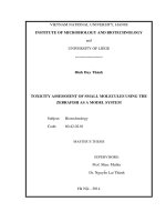
The project area lies approximately between UTM co-ordinates 696000N to 726200N and
386000E and 422000E, a short distance east of Lake Abaya and just south of Gidabo river
flood plain, at an average elevation of 1190 a.m.s.l (fig.1.1). Gidabo irrigation project is
found in Abaya district, Borena zone of Oromia region and Dale district, Sidama zone of
SNNPRS near Dilla town to east of Lake Abaya, located in Dibicha Laluncha Kebele of
Gelana Abaya district, which is situated in Borena zone. The project area lies in the low land,
very close to the Dure and Gola marsh. The command area is situated in the northern part of
Lake Abaya. The northern Lake Abaya area, which is located in the southern part of the Main
Ethiopian Rift (MER), encloses irrigable lands at different places.
Fig. 1.1
Location map of the study area
Engineering Geology
3
School of Earh Sciences, Addis Ababa University
Chapter 1
1.4.
INTRODUCTION
Problem of statement
Failure of embankment dams, except for failures caused by unanticipated catastrophic events
such as earthquakes or overtopping, is almost preceded by warning signals such as increased
rate of deformation, strain discontinuities, cracking, leakage, and pore pressure buildup
(Chugh, 1990). According to WWDSE (2016) Gidabo Dam has faced settlement at the
conduit outlet foundation during the construction time. Due to this unexpected settlement it
may initiate to differential settlement or losing of free board that may possibly cause for
major failures. Therefore, the present research is intended to investigate the problem of
settlement and possible causes responsible for this settlement at Gidabo Dam project. An
attempt is also made to workout possible mitigation measures to overcome likely dam
stability problems.
1.5.
Objectives
1.5.1. General objective
The main objectives of this study are to assess the possible causes of partial settlement in the
dam and to estimate the amount of settlement in the dam.
1.5.2. Specific objectives
To determine the engineering geology properties of the foundation and the embankment
material used in the dam
To review the design of the dam
To estimate the possible settlement potential on the dam foundation
To determine the cause for the partial settlement of the dam by comparing the actual
settlement happened in the dam with the estimated settlement
To workout possible remedial measures for the safety and stability of the dam
1.6.
General Methodology
The results of this study are based on the combination of the following fundamental works
that are conducted sequentially. In order to achieve the objectives of the present study
systematic methodology has been followed which includes;
Literature review to have an overview of geological, geomorphologic, hydro-geological
and engineering geological condition of the dam site and the surrounding areas.
Engineering Geology
4
School of Earh Sciences, Addis Ababa University
Chapter 1
INTRODUCTION
Collection of secondary data such as; in-situ and laboratory results, construction reports
and report after partial settlement happened.
Field investigation and Collection of soil samples from borrows areas for laboratory
testing and analysis to determine various index properties with specific emphasis on
consolidation test.
Analysis of effective stress and pore water pressure conditions from the laboratory result
and field data.
Analysis of settlement in the foundation and within the embankment under all conditions
by using different analysis methods and empirical relationships.
Interpretation of the result for the determination of possible cause for the partial
settlement on the dam during construction.
1.7.
Importance of the study
The results and the findings of the present study are expected to be utilized by the Project
Authorities or by any other individual or organization. The data generated through this study
will also be utilized by the later researchers intending to work on the same subject or in the
same study area. Since the present research study was intended to assess the causes for the
partial settlement of the dam therefore, it may be possibly helpful for the mitigation of the
problem through life time of the dam.
The present study will also be a guide line for geotechnical engineers and engineering
geologist who are involved in foundation and construction material assessment for
embankments. In addition it may also provide a good guideline for embankment dam
designers and professionals involved in supervision of embankment construction especially
on those areas which generally demonstrates settlement problems.
1.8.
Limitation and the Scope of the study
The present research was focused on assessment of causes for settlement therefore, it
demanded reliable data. During the field work it was difficult to collect undisturbed samples
from the foundation as it is now buried under embankment fill. However, in order to have the
representative foundation samples, the samples were collected from the nearby locations.
Engineering Geology
5
School of Earh Sciences, Addis Ababa University
Chapter 1
INTRODUCTION
Besides, secondary data was also utilized to make necessary analysis. The present research
was conducted under time, resources and the financial constraints.
1.9.
Chapter Scheme
The present research study is compiled into seven chapters and a brief description of each
chapter is presented hereunder;
Chapter 1: presents general introduction to the problem, the study area, location and
accessibility, statement of the problem, objectives, methodology, importance of the study and
limitation and scope of the study.
Chapter 2: this chapter presents literature review on the settlement problems in dams, review
on conduit settlement, dam design review and theory on analyzing settlement.
Chapter 3: is on the study area, this chapter is focused on project background and salient
feature, geology, hydrogeology and seismicity of the study area.
Chapter 4: presents the general methodology followed in the present study. It provides a
description on type of data collected, processing and analysis followed.
Chapter 5: describes about data presentation, processing and analyzing.
Chapter 6: is about result and discussion. It presents analysis results on causes of settlement
and the possible mitigation measurements.
Chapter 7: presents conclusion and recommendation
*****
Engineering Geology
6
School of Earh Sciences, Addis Ababa University
Chapter 2
CHAPTER- 2
2.1
LITERATURE REVIEW
LITERATURE REVIEW
Embankment Dams Settlement problem
The behavior of concrete dams is significantly different from that of embankment dams
because of the differences in construction materials. In concrete dams, deformation is
assumed to be elastic and any permanent deformation may be caused either by the adaptation
of the foundation to the new load, aging of concrete, or foundation rock fatigue. In the case of
embankment dams the deformation is usually permanent. Permanent vertical settlement of the
fill material continues at a decreasing rate for decades after construction, while permanent
horizontal deformation of the embankment is caused by the reservoir water pressure. The
deformation values for concrete can be in millimeters or centimeters, however for
embankment dams it can be in centimeters or decimeters (Saverio, 1993).
Earth embankments are massive structures that inherently have movements and seepage.
Consolidation of the embankment and the foundation occurs most rapidly during construction
and at a lesser rate for an extended period of time thereafter. The initial filling and its
accompanying saturation may temporarily accelerate the consolidation of the upstream
section of the embankment, and initial filling will also cause downstream seepage to develop.
Consolidation of the embankment and the foundation is accompanied by transverse and
longitudinal movements that may result in transverse and longitudinal cracks (Robert, 1988).
The predicted amounts of consolidation, movement and seepage should be determined by
analyses during the design stage. These analyses should be reviewed at the end of
construction, and modified if the as-constructed engineering characteristics are different from
those assumed during design (Robert, 1988).
Load conditions during construction are induced by the progressive placement of compacted
layers of material. The construction of an embankment dam is always associated with and
followed by a differential settlement of its crest and slopes. Under unfavorable conditions
they can be associated with the formation of open cracks across the impervious section of the
dam. After the dam has been completed, the crest continues to settle at a decreasing rate. If
the dam rests on sediments, the settlements of the crest and slopes is increased by the
compression of the foundation materials produced by the weight of the dam and of the
impounded water at a later stage (Terzaghi et al., 1993).
Engineering Geology
7
School of Earh Sciences, Addis Ababa University
Chapter 2
LITERATURE REVIEW
Foundations under conduits should have relatively uniform compressibility characteristics to
prevent differential settlement and movement of conduit joints. Special precautions should be
taken for joints where the conduit connects to a structure, such as an intake structure. This
location may be in an area susceptible to differential settlement due to the differing weights
of the two structures and the foundation beneath them.
An engineered fill to limit settlement may be needed under the intake structure, when the
structure and conduit cannot be located on bedrock or a firm foundation. If the intake
structure is constructed on a pile foundation, special precautions are also required for the first
few joints of the conduit because high stresses can develop as a result of bending stresses
caused by differential settlement. Extending the conduit and locating the intake structure
beyond the limits affected by the embankment dam can reduce these stresses (FEMA, 2015).
2.2. Settlement Analysis
When a distributed load from a structure is applied to a soft soil stratum, the following three
components of settlement are commonly distinguished (Das, 2008):
1. Immediate settlement (also called initial or undrained settlement), which takes place
immediately upon load application and, if the soil is saturated, deformation is at constant
volume caused by the shear strains beneath the loaded area. Little drainage takes place when
the clay has a low permeability. Under the Centre-line of the load, the vertical compression is
accompanied by lateral expansion (Arora, 2004).
2. Consolidation settlement, the increase in vertical pressure due to the weight of the
structure constructed on top of saturated soft clays and organic soil will initially be carried by
the pore water in the soil. This increase in pore water pressure is known as an excess pore
water pressure (u). The excess pore water pressure will decrease with time as water slowly
flows out of the cohesive soil. This flow of water from cohesive soil (which has a low
permeability) as the excess pore water pressures slowly dissipate is known as primary
consolidation, or simply consolidation. This is a time-dependent process and produces
mainly volume change, but shear deformations are also involved, leading to further
settlement (Arora, 2004; Das, 2008).
3. Secondary compression settlement (often also termed drained creep) the main part of
which takes place after essentially complete dissipation of excess pore water pressures, i.e. at
Engineering Geology
8
School of Earh Sciences, Addis Ababa University
Chapter 2
LITERATURE REVIEW
practically constant effective stresses. In practical cases, it is often assumed that secondary
compression does not start until after primary consolidation is completed (Arora, 2004).
Immediate Settlement in Cohesive Soils
According to Venkatramaiah (2006) if saturated clay is loaded rapidly, excess hydrostatic
pore pressures are induced; the soil gets deformed with virtually no volume change and due
to low permeability of the clay little water is squeezed out of the voids. The vertical
deformation due to the change in shape is the immediate settlement.
The immediate settlement of a flexible foundation, According to Terzaghi (1943), is given
by:
(
)
…..eq. 2.1
Where;
=immediate settlement at a corner of a rectangular flexible foundation of size L × B,
B = Width of the foundation,
q = Uniform pressure on the foundation,
Es= Modulus of elasticity of the soil beneath the foundation,
ν = Poisson’s ratio of the soil, and
It= Influence Value, which is dependent on L/B (Table 2.1),
L= length of the foundation
Table 2.1
The value of It after Terzaghi, 1943
L/B
1
2
3
4
5
Influence value It
0.56
0.76
0.88
0.96
1
An earth embankment may be taken as flexible and the above formula (eq.2.1) may be used
to determine the immediate settlement of the soil below such a construction (Venkatramaiah,
2006). But for the conduit outlet foundation the above formula is not convenient since the
foundation is rigid.
The following formula is appropriate:
…..eq. 2.2
Engineering Geology
9
School of Earh Sciences, Addis Ababa University
Chapter 2
LITERATURE REVIEW
Elastic settlement from SPT value
Terzaghi and Peck (1948, 1967) proposed a correlation for the allowable bearing capacity,
standard penetration number (N60), and the width of the foundation (B) by the following
relation.
(
)
…..eq. 2.3
Where q=bearing pressure in kN/m2, B = width of foundation (m), CW = ground water table
correction,
CD=correction for depth embedment=
and Df = depth embedment.
The magnitude of Cw is equal to 1.0 if the depth of water table is greater than or equal to 2B
below the foundation, and it is equal to 2.0 if the depth of water table is less than or equal to
B below the foundation. The N60value that is to be used in equation should be the average
value of N up to a depth of about 3B to 4B measured from the bottom of the foundation.
Janbu approach
The Janbu approach was proposed by Professor Nilmar Janbu in the early 1960s. The main
concept of this approach combines the basic principles of linear and non-linear stress-strain
behavior. For linear stress-strain behavior Hook’s low is the most recognized approach
however Stress-strain behavior is non-linear for most soils. The non-linearity cannot be
disregarded when analyzing compressible soils, such as silts and clays, that is, the linear
elastic modulus approach is not appropriate for these soils. The method applies to all soils,
clays as well as sand. By the Janbu method, the relation between stress and strain is simply a
function of two non-dimensional parameters that are unique for any soil: a stress exponent, J,
and a modulus number, m (Fellenuis, 2015).
The Janbu expressions for strain are derived into four categories according to the nature of
the soil particle. They are expression for cohesionless, dens coarse grained soil, sandy or silty
soil, and cohesive soils. In the present paper cohesive soils and sandy or silty soils expression
were used.
For cohesive soils J=0 and normally consolidated clay;
…..eq. 2.4
Engineering Geology
10
School of Earh Sciences, Addis Ababa University
Chapter 2
LITERATURE REVIEW
For sandy or silty soil J=0.5
√ )…..eq. 2.5
(√
Where; ε= strain induced by increase of effective stress in kPa,
= original effective stress
= final effective stress and
= modulus number.
Modulus number is determined from empirical relationships or from laboratory and field
tests.
For sand and silty soil in kPa:
√
…..eq. 2.6
Where; E= Elastic Modulus and
= average change of effective stress (=
)
According to Schmertmann, 1970 as stated in Das (2008) the modulus E of elasticity of
granular soils has been correlated to the field standard penetration number N:
…..eq. 2.7
For cohesive soils by using conventional method or from odometer test:
…..eq. 2.8
Where; = initial void ratio and
= compression index.
Finally, the deformation of a soil layer, s, is the strain, ε, times the thickness, h, of the layer.
The settlement, S, of the foundation is the sum of the deformations of the soil layers below
the foundation.
∑
∑
…..eq. 2.9
One dimensional consolidation primary settlement
The phenomenon of consolidation occurs in clays because the initial excess pore water
pressures cannot be dissipated immediately owing to the low permeability. The theory of one
dimensional consolidation, advanced by Terzaghi (1925), can be applied to determine the
total compression or settlement of a clay layer as well as the time-rate of dissipation of excess
Engineering Geology
11
School of Earh Sciences, Addis Ababa University
Chapter 2
LITERATURE REVIEW
pore pressures and hence the time-rate of settlement. The settlement computed by this
procedure is known as that due to primary compression since the process of consolidation as
being the dissipation of excess pore pressures alone is considered (Venkatramaiah, 2006).
Normally consolidated soils are usually found as recent alluvial deposits, and are mainly
composed of silt and clay sized particles. It is extremely rare to find normally consolidated
soils inland, away from the rivers or lakes in which they were deposited. Soils from the study
area are recently river deposited. Therefore, the present investigation was done by
considering soils to be normally consolidated soils.
For normally consolidated clay soils the following equation can be used;
…..eq. 2.10
Where;
= primary settlement,
initial void ratio,
= initial height of the layer,
= average original effective stress and
= compression index,
=
=average change of vertical
stress.
Time Rate of Consolidation
Time-rate of settlement is dependent, in addition to other factors, upon the drainage
conditions of the clay layer. If the clay layer is sandwiched between sand layers, pore water
could be drained from the top as well as from the bottom and it is said to be a case of double
drainage. If drainage is possible only from either the top or the bottom, it is said to be a case
of single drainage. In the former case, the settlement proceeds much more rapidly than in the
latter (Venkatramaiah, 2006).
Terzaghi (1925) advanced his theory of one dimensional consolidation based upon the
following assumptions, the mathematical implications being given in parentheses:
(i)
The soil is homogeneous (kz is independent of z).
(ii)
The soil grains and water are virtually incompressible (ˠw is constant and volume
change of soil is only due to change in void ratio).
(iii)
The behavior of infinitesimal masses in regard to expulsion of pore water and
consequent consolidation is no different from that of larger representative masses
(Principles of calculus may be applied).
(iv)
The compression is one-dimensional (u varies with z only).
(v)
The flow of water in the soil voids is one-dimensional, Darcy’s law being valid.
Engineering Geology
12
School of Earh Sciences, Addis Ababa University
Chapter 2
(vi)
LITERATURE REVIEW
Certain soil properties such as permeability and modulus of volume change are
constant; these actually vary somewhat with pressure. (k and mv are independent of
pressure).
(vii)
The pressure versus void ratio relationship is taken to be the idealised one (av is
constant).
(vii)
Hydrodynamic lag alone is considered and plastic lag is ignored, although it is known
to exist. (The effect of k alone is considered on the rate of expulsion of pore water).
The theory of one-dimensional consolidation, advanced by Terzaghi, can be applied to
determine the total compression or settlement of a clay layer as well as the time-rate of
dissipation of excess pore pressures and hence the time-rate of settlement. The settlement
computed by this procedure is known as that due to primary compression since the process of
consolidation as being the dissipation of excess pore pressures alone is considered
(Venkatramaiah, 2006).
The calculations are based upon the equation:
…..eq. 2.14
Where; T=non-dimensional time factor, Cv= coefficient of consolidation and H= thickness of
the layer
The consolidation tests in the present studywere done using British Standard the coefficient
of consolidation, Cv (in m2/year), was determine using BS 1377, 1975 relation as following:
……eq. 2.15
Where; H1= is the height of the specimen at the start of the loading increment (in mm),
H2=is the height of the specimen at the end of the loading increment (in mm) and t50= the
time takes to reach 50% consolidation
Coefficient of consolidation for each sample was calculated for different load increment and
an average value of Cv for the desired load range was determined.
Engineering Geology
13
School of Earh Sciences, Addis Ababa University
Chapter 2
LITERATURE REVIEW
2.3 Review on conduit settlement problem
According to WWDSE (2009) the allowance of 1 to 2% of the height of the dam should be
provided for settlement in the foundation and the embankment. For Gidabo dam, a total
settlement allowance of 3% of the dam height has been provided.
During the construction of Gidabo Dam the conduit facing settlement which was noticed
when the contractor tried to put joint sealant on December 26/2015. Since then measurement
and visual observation was taken. The result of surveying measurement showed that the
settlement is continuing even after further construction was stopped. As a result of this the
metal sheet, welded at the start of the conduit is showing cracks. However, starting from day
30 i.e. about 25 days after the construction of embankment was stopped, the settlement seems
to be stopped and the minor differences are attributed to errors in surveying measurement.
The maximum settlement recorded at a chainage 0+40 after 55 days was 42.1 cm. The Table
2.3 shows the measured settlement along the conduit. The settlement measurements were
taken from 30/12/2015 to 2/22/2016 (WWDSE, 2016).
Table 2.2
S.No
1
2
3
4
5
6
7
8
9
10
11
Day
Chainage
0+00
0+9.16
0+19.15
0+29.15
0+39.19
0+49.37
0+59.23
0+69.14
0+79.20
0+89.11
0+98.71
Measured settlement along the conduit in meter (distance 0+00 refers to start of the conduit)
1
Total
0.231
0.224
0.279
0.294
0.296
0.252
0.173
0.083
0.004
0.006
0.034
5
total
0.295
0.262
0.301
0.313
0.325
0.274
0.190
0.091
0.009
0.005
0.35
10
total
0.312
0.301
0.304
0.349
0.364
0.302
0.211
0.102
0.014
0.001
0.029
15
total
0.317
0.315
0.352
0.364
0.372
0.319
0.225
0.113
0.021
0.006
0.037
20
Total
0.333
0.329
0.368
0.379
0.389
0.334
0.237
0.121
0.026
0.008
0.039
25
total
0.336
0.331
0.371
0.381
0.387
0.335
0.237
0.120
0.024
0.004
0.039
30
total
0.343
0.340
0.377
0.389
0.399
0.340
0.241
0.122
0.024
0.002
0.036
35
Total
0.350
0.343
0.382
0.393
0.401
0.345
0.243
0.124
0.021
0.004
0.035
35
Total
0.354
0.349
0.386
0.396
0.403
0.349
0.246
0.126
0.025
0.003
0.037
40
total
0.355
0.391
0.400
0.410
0.351
0.248
0.126
0.024
0.003
0.034
50
total
0.364
0.398
0.408
0.416
0.358
0.254
0.133
0.030
0.009
0.038
55
total
0.367
0.403
0.413
0.421
0.364
0.262
0.142
0.131
0.012
0.041
After the settlement was noticed professional team was assigned to investigate and put
possible remedial measures. This team predicted settlement during the construction (current
height) and at post construction by using SIGMA/W Finite Element Model (FEM) software.
Most of the parameters adopted for this model were from literature. The parameters used
were Poission’s Ratio and Modulus of Elasticity. During the current stage at the height of 13
m the maximum settlement at start of conduit 0+00 is about 24 cm compared to actual 35cm
obtained from surveying. The maximum settlement that this model has estimated was found
on chainage +40 is 50 cm compared to 42cm the actual measurement. The maximum
settlement at the end of the construction (crest level) at start of the conduit is 42cm and the
Engineering Geology
14
School of Earh Sciences, Addis Ababa University
Chapter 2
LITERATURE REVIEW
maximum possible deformation along the length of the conduit is estimated to be 67cm which
is at the start of the conduit.
Settlement due to reservoir loading has been also made. The additional settlement due to
reservoir loading is insignificant, as it increase only 3cm around conduit starting and vanishes
after around 25m along the conduit compared to FEM done for end of construction
(WWDSE, 2016).
2.4 Dam Design Review of Gidabo Dam
2.4.1 Original design of Gidabo dam
The original dam design was done in 2008 by Water Works Design and Supervision
Enterprise (WWDSE) in association with consulting Engineering Service (India) (WWDSE,
2008).
Gidabo Irrigation project was proposed with construction of about 20m high rock-fill dam
with central clay core at Gidabo dam site with spillway, two outlets for Left bank and Right
bank main Canals off taking from the dam on river Gidabo. The project is planned to irrigate
net area of 5193 hectare of land by Left bank main Canal and 2181 ha. of net area by Right
bank main Canal with total irrigation of 7374 ha land through its canal distribution network.
Further, the spillway is designed as a chute spillway. Due to topographic constraints, the
overflow portion of spillway is made curved so as to get more length. The location of the
spillway is at the left bank of the river. The main components of the spillway are approach
channel, ogee type overflow spillway, discharge channel with sub critical slope and stilling
basin as the terminal structure (WWDSE, 2008).
For river diversion during construction, a conduit (2 x 2m) will be laid on the left side of the
main river channel. The length of the conduit will be approximately equal to the bottom
width of the dam at the location of the conduit. The opening of the conduit is designed to pass
the dry season flow during the construction. The diversion conduit will serve effectively only
for dry season construction period and to be plugged after the construction of the dam and
appurtenant structures are over. Irrigation outlet structures are closed conduits. There are two
outlets, one at left bank and the other on the right. The irrigation and dry season diversion
conduits will all be constructed on pile foundations (WWDE, 2008).
The impervious core of Gidabo Dam is proposed to be flanked by a 1V:2.5H upstream slope
and 1V:2.0H to 1V:2.5H downstream slope free draining earth fills.
Engineering Geology
15
School of Earh Sciences, Addis Ababa University