Ashrae 2003 HVAC applications
Bạn đang xem bản rút gọn của tài liệu. Xem và tải ngay bản đầy đủ của tài liệu tại đây (39.55 MB, 814 trang )
2003 HVAC Applications
(SI
(SI Edition)
Edition)
Contributors
Preface
Technical Committees, Task Groups, and
Technical Resource Groups
COMFORT APPLICATIONS
MAIN MENU
HELP
TERMINOLOGY
• A14.
Laboratories
• A15.
Engine Test Facilities
• A16.
Clean Spaces
• A17.
Data Processing and Electronic Office Areas
• A18.
Printing Plants
• A19.
Textile Processing Plants
• A20.
Photographic Material Facilities
• A21.
Museums, Libraries, and Archives
• A22.
Environmental Control for Animals and Plants
• A23.
Drying and Storing Selected Farm Crops
• A24.
Air Conditioning of Wood and Paper Product
Facilities
• A01.
Residences
• A02.
Retail Facilities
• A03.
Commercial and Public Buildings
• A04.
Places of Assembly
• A05.
Hotels, Motels, and Dormitories
• A06.
Educational Facilities
• A07.
Health Care Facilities
• A08.
Justice Facilities
• A25.
Power Plants
• A09.
Surface Transportation
• A26.
Nuclear Facilities
• A10.
Aircraft
• A27.
Mine Air Conditioning and Ventilation
• A11.
Ships
• A28.
Industrial Drying Systems
INDUSTRIAL APPLICATIONS
• A29.
Ventilation of the Industrial Environment
• A12.
Industrial Air Conditioning
• A30.
Industrial Local Exhaust Systems
• A13.
Enclosed Vehicular Facilities
• A31.
Kitchen Ventilation
More . . .
2003 HVAC Applications
(SI
(SI Edition)
Edition)
ENERGY-RELATED APPLICATIONS
• A32.
Geothermal Energy
• A33.
Solar Energy Use
• A34.
Thermal Storage
BUILDING OPERATIONS AND MANAGEMENT
• A35.
Energy Use and Management
• A36.
Owning and Operating Costs
• A37.
Testing, Adjusting, and Balancing
• A38.
Operating and Maintenance Management
• A39.
Computer Applications
• A40.
Building Energy Monitoring
• A41.
Supervisory Control Strategies and Optimization
• A42.
New Building Commissioning
GENERAL APPLICATIONS
• A43.
Building Envelopes
• A44.
Building Air Intake and Exhaust Design
• A45.
Control of Gaseous Indoor Air
Contaminants
• A46.
Design and Application of Controls
• A47.
Sound and Vibration Control
• A48.
Water Treatment
• A49.
Service Water Heating
• A50.
Snow Melting and Freeze Protection
• A51.
Evaporative Cooling Applications
• A52.
Fire and Smoke Management
• A53.
Radiant Heating and Cooling
• A54.
Seismic and Wind Restraint Design
• A55.
Electrical Considerations
• A56.
Codes and Standards
INDEX
Back . . .
ASHRAE Research: Improving the Quality of Life
The American Society of Heating, Refrigerating and Air-Conditioning Engineers is the world’s foremost technical society in the
fields of heating, ventilation, air conditioning, and refrigeration. Its
members worldwide are individuals who share ideas, identify
needs, support research, and write the industry’s standards for testing and practice. The result is that engineers are better able to keep
indoor environments safe and productive while protecting and preserving the outdoors for generations to come.
One of the ways that ASHRAE supports its members’ and industry’s need for information is through ASHRAE Research. Thousands of individuals and companies support ASHRAE Research
annually, enabling ASHRAE to report new data about material
properties and building physics and to promote the application of
innovative technologies.
The chapters in ASHRAE Handbooks are updated through the
experience of members of ASHRAE technical committees and
through results of ASHRAE Research reported at ASHRAE meetings and published in ASHRAE special publications and in
ASHRAE Transactions.
For information about ASHRAE Research or to become a member, contact ASHRAE, 1791 Tullie Circle, Atlanta, GA 30329; telephone: 404-636-8400; www.ashrae.org.
The 2003 ASHRAE Handbook
The 2003 ASHRAE Handbook—HVAC Applications contains
chapters on a broad range of applications, written to help design
engineers use equipment and systems described in other Handbook
volumes. This edition includes two new chapters, Chapter 8, Justice
Facilities, and Chapter 55, Electrical Considerations. Nearly every
Applications chapter has been revised for current requirements and
techniques. The ASHRAE technical committees that prepare chapters have provided new information, clarified existing information,
deleted obsolete material, and reorganized chapters to make the
Handbook more understandable and easier to use. Some of the revisions are as follows:
• Chapter 7, Health Care Facilities, contains extensive updates to
HVAC requirements for hospitals, including new temperature and
humidity design guidelines for various facility areas.
• Chapter 8, Justice Facilities, is a new chapter with information on
related terminology, requirements, and design considerations for
these facilities.
• Chapter 14, Laboratories, has new data on biological safety cabinets and scale-up laboratories, and research updates on exhaust
stack location and caging system ventilation.
• Chapter 21, Museums, Libraries, and Archives, rewritten, contains more information on pollutant sources, indoor air quality,
and threats to artifacts.
• Chapter 26, Nuclear Facilities, has updates for regulatory requirements plus added information on international reactor designs
and standards, cascade ventilation, heavy water reactors, and gascooled reactor HVAC systems.
• Chapter 27, Mine Air Conditioning and Ventilation, updated for
current practice, has expanded text on ventilation system design,
health and safety, and new examples, including one using the factor-of-merit method for designing direct-contact heat exchangers.
• Chapter 29, Ventilation of the Industrial Environment, has been
completely rewritten for clarity and ease of use.
• Chapter 30, Industrial Local Exhaust Systems, has been extensively revised and refocused for ease of use.
• Chapter 31, Kitchen Ventilation, has new cooking emission and
hood flow rate information, plus schlieren photographs of hood
tests showing actual containment and spillage.
• Chapter 32, Geothermal Energy, updated for new research, has
expanded text on ground-source heat pumps, covering site characterization, thermal testing, load calculations, borehole options,
design strategy, water quality, well pump control, and horizontal
closed-loop systems.
• Chapter 34, Thermal Storage, contains updates for research, operation and control, and combustion turbine inlet air cooling in storage applications.
• Chapter 35, Energy Use and Management, retitled and rewritten,
also has updated DOE energy consumption data.
Copyright © 2003, ASHRAE
• Chapter 36, Owning and Operating Costs, contains new service
life considerations, energy cost analysis resources, and updates
for deregulation issues and ASHRAE research.
• Chapter 37, Testing, Adjusting, and Balancing, has a rewritten
hydronic balancing section, and updated text on instrumentation
and sound and vibration testing.
• Chapter 38, Operation and Maintenance Management, substantially revised, has a new section on results-oriented maintenance
management.
• Chapter 39, Computer Applications, has new and revised information on hardware, development tools, networking, the Internet,
web sites, and application software and utilities for HVAC design
tasks, simulation, business management, and monitoring and
control.
• Chapter 42, New Building Commissioning, rewritten and
expanded, has more information on commissioning at every
stage, from owner project requirement development through
occupancy and operation.
• Chapter 44, Building Air Intake and Exhaust Design, has updates
from ASHRAE research, covering dilution equations, stack
height estimating, air intake design, and the dilution effects of
architectural screens.
• Chapter 47, Sound and Vibration Control, updated for current
technology and standards, also has new sections on emergency
generators and plumbing system noise.
• Chapter 50, Snow Melting and Freeze Protection, retitled, now
covers freeze protection systems, and has updates from ASHRAE
research on transient analysis of snow-melting performance.
• Chapter 55, Electrical Considerations, a new chapter on building
electrical issues for HVAC equipment, has sections on electrical
principles, codes, performance, safety, power quality, motorstarting effects, and rates.
This Handbook is published both as a bound print volume and in
electronic format on a CD-ROM. It is available in two editions: one
using inch-pound (I-P) units of measurement, the other using the
International System of Units (SI).
Corrections to the 2000, 2001, and 2002 Handbooks are posted
on the ASHRAE web site at . Corrections for
this volume will be reported in the 2004 ASHRAE Handbook—
HVAC Systems and Equipment and on the ASHRAE web site.
To make suggestions for improving a chapter or for information
on how you can help revise a chapter, please comment using a form
on the ASHRAE web site; or e-mail ; or write
to Handbook Editor, ASHRAE, 1791 Tullie Circle, Atlanta, GA
30329; or fax 404-321-5478.
Mark S. Owen
ASHRAE Handbook Editor
CONTRIBUTORS
In addition to the Technical Committees, the following individuals contributed significantly
to this volume. The appropriate chapter numbers follow each contributor’s name.
Gregory J. Rosenquist (1)
Lawrence Berkeley National Laboratory
Mark Colino (13)
H. Michael Hughes (1)
Kelly Giblin (13)
James G. Crawford (1)
Trane
Van D. Baxter (1)
Oak Ridge National Laboratory
Lawrence Schoen (2)
Schoen Engineering
Paula Concannon (2)
Munters DH
Reinhold Kittler (2)
Dectron
E. Doug Fitts (3, 5, 8)
St. Louis County Department of Public
Works
Itzhak H. Maor (3, 5)
PWI Energy Inc.
Joseph F. Scolaro (3)
Scolaro Engineering Consultants
Ralph Kittler (4)
Dectron
Richard Hermans (6)
Center for Energy & Environment
Douglas Erickson (7)
Jeffrey M. Hardin (7)
U.S. Army Corps of Engineers
Lynn F. Werman (5, 6, 7)
HDR Architecture
Gary Prusak (9)
Bombardier Transportation
James J. Bushnell (9)
HVAC Consulting Services
Kenneth R. Hesser (9)
LTK Engineering Services
Nicholas Zupp (9)
Delphi Automotive
Robert Cummings (9)
Cummings Engineering Services
Srini Natarajan (9)
Lennox Industries
Richard Johnson (10)
The Boeing Company
Christopher Spunar (11)
Carrier Corporation
Rich Evans (12, 15, 17, 25, 26)
Ravisankar Ganta (12, 26)
Bechtel
Copyright © 2003, ASHRAE
Parsons Brinckerhoff Quade & Douglas Inc.
New Jersey Transit
Steve Presser (13)
ACME Engineering Products, Inc.
Anthony York (13)
Port Authority of New York/New Jersey
Leonard Schwartz (14)
Louis Hartman (14)
Harley Ellis
Patrick Carpenter (14)
TKLP
Ivan Thomas (16)
P2S Engineering, Inc.
William Tschudi (16)
Lawrence Berkeley National Laboratory
Charles C. Shieh (16, 17, 20, 24, 25)
CYS, LLC
Mike Connor (17, 19, 28)
Connor Engineering
Norm Maxwell (18)
Carrier Corporation
John Riley (20, 25, 26)
Black & Veatch
Robert Baker (21)
BBJ Environmental
Cecily Grzywacz (21)
The Getty Conservation Institute
Albert J. Heber (22)
Purdue University
Farhad Memarzadeh (22)
National Institutes of Health
Gerald L. Riskowski (22)
Texas A&M University
Yuanhui Zhang (22)
University of Illinois
Roger C. Brook (23)
Michigan State University
Deep Ghosh (25, 26)
Southern Company
Thomas B. Axley (25, 29, 30)
TVA
Matt Hargan (26)
Hargan Engineering
John Marks (27)
National Underground Science Laboratory
Todd A. Talbott (29, 30)
McGill Airflow Corporation
Wayne M. Lawton (29, 30)
ARCADIS
Doug Horton (31)
D J Horton & Associates
Richard T. Swierczyna (31)
Architectural Energy Corporation
Stephen L. Brown (31)
LC Systems
Steven Kavanaugh (32)
University of Alabama
William Murphy (32)
University of Kentucky
Kevin Rafferty (32)
Geo-Heat Center
Mark Hertel (33)
Sunearth, Inc.
James Elleson (34)
University of Wisconsin-Madison
Richard Kooy (34)
Chicago Bridge and Iron Company
William Bahnfleth (34)
The Pennsylvania State University
Adam Hinge (35)
Sustainable Energy Partnerships
Andrew Rudin (35)
Cedric Trueman (35)
Trueman Engineering Services
Lawrence G. Spielvogel (35)
Lawrence G. Spielvogel, Inc.
Bill Thomaston (36)
Alabama Gas Corporation
Dennis H. Tuttle (37)
Frederick A. Lorch (37)
Phoenix Controls Corporation
Gaylon Richardson (37)
Engineered Air Balance
Gerald J. Kettler (37)
Air Engineering & Testing, Inc.
Mark Hegberg (37)
ITT Bell & Gossett
Ted N. Carnes (37)
Pelton Marsh Kinsella
William K. Thomas (37)
Thomas Young Associates Inc.
John Rydzewski (38)
EI Du Pont de Nemours and Company
Richard Danks (38)
NASA—Glenn Research Center
Scott Sepsy (38)
Mike Ratcliff (44)
Claude Laval Corporation
David Wilson (44)
David Branson (39)
Mark Leonardelli (48)
University of Alberta
Compliance Services Group, Inc.
Nalco Chemical
John Carter (44)
Mark Hydeman (39)
Robert Petterson (48)
Cemak Peterka Petersen, Inc.
Taylor Engineering
Marley Cooling Tower Company
Brian C. Krafthefer (45)
Mike Pouchak (39)
Charles H. Sanderson (48)
Honeywell, Inc.
Honeywell
Superior Manufacturing Division
Carolyn M. Kerr (45)
Kenneth Gillespie (40)
Anne M. Wilson (48)
InAir Environmental Ltd.
PG&E
Nalco Chemical
Dean T. Tompkins (45)
Mark Ternes (40)
Michael MacDonald (40)
Brad Windon (49)
University of Wisconsin-Madison
Oak Ridge National Laboratory
Derald G. Welles (45)
William R. Mixon (40)
Douglas W. Vanosdell (45)
Tech Support Services
Research Triangle Institute
Southern California Gas Company
Rex Scare (49)
Armstrong-Yoshitake
Nick Agopian (45)
Arthur Dexter (41)
Rheem Manufacturing Company
Daryl L. Hosler (49)
Steril-Aire USA, Inc.
Oak Ridge National Laboratory
Will Haag (49)
Circul-Aire
University of Oxford
A.O. Smith Water Products Company
Paul R. Nelson (45)
James E. Braun (41)
J.D. Spitler (50)
R.J. Reynolds Tobacco Co.
Purdue University
Oklahoma State University
Jim Winston (46)
John Mitchell (41)
University of Wisconsin-Madison
Mark Cascia (41)
Peter Donohue (50)
Tyco Thermal Controls
John Kettler (46)
William Chapman (50)
Monica Amalfitano (46)
Siemens Building Technologies
Natascha Castro (41)
Birol I. Kilkis (50, 53)
P2S Engineering, Inc.
Watts Radiant
Steven Taylor (46)
NIST
Leon E. Shapiro (51)
Taylor Engineering
Andy Nolfo (42)
ADA Systems
Eric Rosenberg (47)
The Murphy Company
John H. Klote (52)
Kirkegaard Associates
John Rieke (42)
John H. Klote, Inc.
Jerry Lilly (47)
Karges-Faulconbridge, Inc. (KFI)
Karl Stum (42)
Paul Meisel (54)
JGL Acoustics
Kinetics Noise Control
John Paulauskis (47)
CH2M HILL
Colleen S. Smith (55)
HBE Corporation
Andre Desjarlais (43)
Dais Analytic Corporation
Rich Peppin (47)
Oak Ridge National Laboratory
William B. Rose (43)
William R. Leizear, Sr. (48)
RWDI
Princeton University
Lawrence Markel (55)
Scantek, Inc.
Sentech Inc.
Mark Hodgson (48)
University of Illinois
Marvin Thedford (55)
Clayton Group Services
ASHRAE HANDBOOK COMMITTEE
Kenneth W. Cooper, Chair
Charles A. Francis
2003 HVAC Applications Volume Subcommittee: Kenneth W. Cooper, Chair
Douglas C. Hittle
Henry Manczyk
Michael A. Ratcliff
Brian A. Rock
ASHRAE HANDBOOK STAFF
Mark S. Owen, Editor
Heather E. Kennedy, Associate Editor
Nancy F. Thysell, Typographer/Page Designer
Barry Kurian, Manager and Jayne E. Jackson
Publishing Services
W. Stephen Comstock,
Director, Communications and Publications
Publisher
Derald G. Welles
CHAPTER 1
RESIDENCES
Single-Family Residences ............................................................................................................... 1.2
Multifamily Residences .................................................................................................................. 1.5
Manufactured Homes ..................................................................................................................... 1.6
S
PACE-CONDITIONING systems for residential use vary with
both local and application factors. Local factors include energy
source availability (present and projected) and price; climate; socioeconomic circumstances; and the availability of installation and
maintenance skills. Application factors include housing type, construction characteristics, and building codes. As a result, many different systems are selected to provide combinations of heating,
cooling, humidification, dehumidification, and air filtering. This
chapter emphasizes the more common systems for space conditioning of both single-family (i.e., traditional site-built and modular or
manufactured homes) and multifamily residences. Low-rise multifamily buildings generally follow single-family practice because
constraints favor compact designs. Retrofit and remodeling construction also adopt the same systems as those for new construction,
but site-specific circumstances may call for unique designs.
It passes initially through the air filter (2). The circulating blower
(3) is an integral part of the furnace (4), which supplies heat during
winter. An optional humidifier (10) adds moisture to the heated air,
which is distributed throughout the home via the supply duct (9).
When cooling is required, the circulating air passes across the evaporator coil (5), which removes heat and moisture from the air.
Refrigerant lines (6) connect the evaporator coil to a remote condensing unit (7) located outdoors. Condensate from the evaporator
is removed through a drainline with a trap (8).
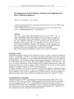
Figure 2 shows a split-system heat pump, supplemental electric
resistance heaters, a humidifier, and an air filter. The system functions as follows: Air from the space enters the equipment through
the return air duct (1) and passes through a filter (2). The circulating
blower (3) is an integral part of the indoor unit (or air handler) of
the heat pump (4), which supplies heat via the indoor coil (6) during
the heating season. Optional electric heaters (5) supplement heat
from the heat pump during periods of low ambient temperature and
counteract airstream cooling during the defrost cycle. An optional
humidifier (10) adds moisture to the heated air, which is distributed
throughout the home via the supply duct (9). When cooling is
required, the circulating air passes across the indoor coil (6), which
removes heat and moisture from the air. Refrigerant lines (11)
connect the indoor coil to the outdoor unit (7). Condensate from the
indoor coil is removed through a drainline with a trap (8).
Single-package systems, where all equipment is contained in
one cabinet, are also popular in the United States. They are used
Systems
Common residential systems are listed in Table 1. Three generally recognized groups are central forced air, central hydronic, and
zoned systems. System selection and design involve such key decisions as (1) source(s) of energy, (2) means of distribution and delivery, and (3) terminal device(s).
Climate determines the services needed. Heating and cooling are
generally required. Air cleaning (by filtration or electrostatic
devices) can be added to most systems. Humidification, which can
also be added to most systems, is generally provided in heating systems only when psychrometric conditions make it necessary for
comfort and health (as defined in ASHRAE Standard 55). Cooling
systems usually dehumidify as well. Typical residential installations
are shown in Figures 1 and 2.
Figure 1 shows a gas furnace, a split-system air conditioner, a
humidifier, and an air filter. The system functions as follows: Air
from the space enters the equipment through a return air duct (1).
Fig. 1 Typical Residential Installation of Heating, Cooling,
Humidifying, and Air Filtering System
Table 1 Residential Heating and Cooling Systems
Central
Forced Air
Central
Hydronic
Gas
Oil
Electricity
Resistance
Heat pump
Air
Gas
Oil
Electricity
Resistance
Heat pump
Water
Steam
Distribution
system
Ducting
Piping
Terminal
devices
Diffusers
Registers
Grilles
Radiators
Radiant panels
Fan-coil units
Most common
energy
sources
Distribution
medium
Zoned
Gas
Electricity
Resistance
Heat pump
Air
Water
Refrigerant
Ducting
Piping or
Free delivery
Included with
product or same
as forced-air or
hydronic systems
Fig. 1
The preparation of this chapter is assigned to TC 7.6, Unitary and Room
Air Conditioners and Heat Pumps.
Copyright © 2003, ASHRAE
1.1
Typical Residential Installation of Heating, Cooling,
Humidifying, and Air Filtering System
1.2
2003 ASHRAE Applications Handbook (SI)
Fig. 2
Typical Residential Installation of Heat Pump
Fig. 2
Typical Residential Installation of Heat Pump
extensively in areas where residences have duct systems in crawlspaces beneath the main floor and in areas such as the Southwest,
where typically rooftop-mounted packages connect to attic duct
systems.
Central hydronic heating systems are popular both in Europe and
in parts of North America where central cooling has not normally
been provided. New construction, especially in multistory homes,
now typically includes central cooling.
Zoned systems are designed to condition only part of a home at
any one time. They may consist of individual room units or central
systems with zoned distribution networks. Multiple central systems
that serve individual floors or the sleeping and common portions of
a home separately are sometimes used in large single-family houses.
The source of energy is a major consideration in system selection. For heating, gas and electricity are most widely used, followed
by oil, wood, solar energy, geothermal energy, waste heat, coal,
district thermal energy, and others. Relative prices, safety, and environmental concerns (both indoor and outdoor) are further factors in
heating energy source selection. Where various sources are available, economics strongly influence the selection. Electricity is the
dominant energy source for cooling.
Equipment Sizing
The heat loss and gain of each conditioned room and of ductwork
or piping run through unconditioned spaces in the structure must be
accurately calculated in order to select equipment with the proper
heating and cooling capacity. To determine heat loss and gain accurately, the floor plan and construction details must be known. The
plan should include information on wall, ceiling, and floor construction as well as the type and thickness of insulation. Window design
and exterior door details are also needed. With this information, heat
loss and gain can be calculated using the Air-Conditioning Contractors of America (ACCA) Manual J or similar calculation procedures. To conserve energy, many jurisdictions require that the
building be designed to meet or exceed the requirements of
ASHRAE Standard 90.2, Energy-Efficient Design of New LowRise Residential Buildings, or similar requirements.
Proper matching of equipment capacity to the building heat loss
and gain is essential. The heating capacity of air-source heat pumps
is usually supplemented by auxiliary heaters, most often of the electric resistance type; in some cases, however, fossil fuel furnaces or
solar systems are used.
Undersized equipment will be unable to maintain the intended
indoor temperature under conditions of extreme outdoor temperatures. Some oversizing may be desirable to enable recovery from
setback and to maintain indoor comfort during outdoor conditions
that are more extreme than the nominal design conditions. Grossly
oversized equipment can cause discomfort because of short ontimes, wide indoor temperature swings, and inadequate dehumidification when cooling. Gross oversizing may also contribute to
higher energy use by increasing cyclic thermal losses and off-cycle
losses. Variable-capacity equipment (heat pumps, air conditioners,
and furnaces) can more closely match building loads over specific
ambient temperature ranges, usually reducing these losses and
improving comfort levels; in the case of heat pumps, supplemental
heat needs may also be reduced.
Recent trends toward tight building construction with improved
vapor retarders and low infiltration may cause high indoor humidity
conditions and the buildup of indoor air contaminants in the space.
Air-to-air heat-recovery equipment may be used to provide tempered ventilation air to tightly constructed houses. Outdoor air
intakes connected to the return duct of central systems may also be
used when reducing installed costs is the most important task. Simple exhaust systems with passive air intakes are also becoming popular. However, all ventilation schemes increase the building load
and the required system capacity, thereby resulting in greater energy
consumption. In all cases, minimum ventilation rates, as outlined in
ASHRAE Standard 62, should be maintained.
SINGLE-FAMILY RESIDENCES
Heat Pumps
Heat pumps for single-family houses are normally unitary systems; that is, they use single-package units or split systems as illustrated in Figure 2.
Most commercially available heat pumps (particularly in North
America) are electrically powered air-source systems. Supplemental heat is generally required at low outdoor temperatures or during
defrost. In most cases, supplemental or backup heat is provided by
electric resistance heaters.
Heat pumps may be classified by thermal source and distribution
medium in the heating mode as well as the type of fuel used. The
most commonly used classes of heat pump equipment are air-to-air
and water-to-air. Air-to-water and water-to-water types are also used.
Heat pump systems, as contrasted to the heat pump equipment,
are generally described as air-source or ground-source. The thermal
sink for cooling is generally assumed to be the same as the thermal
source for heating. Air-source systems using ambient air as the heat
source/sink are generally the least costly to install and thus the most
commonly used. Ground-source systems usually use water-to-air
heat pumps to extract heat from the ground via groundwater or a
buried heat exchanger.
Ground-Source (Geothermal) Systems. As a heat source/sink,
groundwater (from individual wells or supplied as a utility from
community wells) offers the following advantages over ambient air:
(1) heat pump capacity is independent of ambient air temperature,
reducing supplementary heating requirements; (2) no defrost cycle
is required; (3) although operating conditions for establishing rated
efficiency are not the same as for air-source systems, the seasonal
efficiency is usually higher for heating and for cooling; and (4) peak
heating energy consumption is usually lower. Two other system
types are ground-coupled and surface-water-coupled systems.
Ground-coupled systems offer the same advantages, but because
surface water temperatures track fluctuations in air temperature,
surface-water-coupled systems may not offer the same benefits as
other ground-source systems. Both system types circulate brine or
water in a buried or submerged heat exchanger to transfer heat from
the ground. Direct-expansion ground-source systems, with evaporators buried in the ground, are rarely used. Water-source systems
Residences
1.3
that extract heat from surface water (e.g., lakes or rivers) or city (tap)
water are sometimes used where local conditions permit.
Water supply, quality, and disposal must be considered for
groundwater systems. Caneta Research (1995) and Kavanaugh and
Rafferty (1997) provide detailed information on these subjects.
Secondary coolants for ground-coupled systems are discussed in
Caneta Research (1995) and in Chapter 21 of the ASHRAE Handbook—Fundamentals. Buried heat exchanger configurations may be
horizontal or vertical, with the vertical including both multipleshallow- and single-deep-well configurations. Ground-coupled systems avoid water quality, quantity, and disposal concerns but are
sometimes more expensive than groundwater systems. However,
ground-coupled systems are usually more efficient, especially when
pumping power for the groundwater system is considered. Proper
installation of the ground coil(s) is critical to success.
Add-On Heat Pumps. In add-on systems, a heat pump is
added—often as a retrofit—to an existing furnace or boiler plus fan
coil system. The heat pump and combustion device are operated in
one of two ways: (1) alternately, depending on which is most costeffective, or (2) in parallel. In unitary bivalent heat pumps, the heat
pump and combustion device are grouped in a common chassis and
cabinets to provide similar benefits at lower installation costs.
Fuel-Fired Heat Pumps. Extensive research and development
has been conducted to develop fuel-fired heat pumps. They have
been marketed in North America.
Water-Heating Options. Heat pumps may be equipped with
desuperheaters (either integral or field-installed) to reclaim heat for
domestic water heating when operated in the cooling mode. Integrated space-conditioning and water-heating heat pumps with an
additional full-size condenser for water heating are also available.
include fan coils and radiant panels. Most recently installed residential systems use a forced-circulation, multiple-zone hot water system with a series-loop piping arrangement. Chapters 12, 27, and 32
of the ASHRAE Handbook—Systems and Equipment have more
information on hydronics.
Design water temperature is based on economic and comfort
considerations. Generally, higher temperatures result in lower first
costs because smaller terminal units are needed. However, losses
tend to be greater, resulting in higher operating costs and reduced
comfort due to the concentrated heat source. Typical design temperatures range from 80 to 95°C. For radiant panel systems, design
temperatures range from 45 to 75°C. The preferred control method
allows the water temperature to decrease as outdoor temperatures
rise. Provisions for expansion and contraction of piping and heat
distributing units and for eliminating air from the hydronic system
are essential for quiet, leaktight operation.
Fossil fuel systems that condense water vapor from the flue gases
must be designed for return water temperatures in the range of 50 to
55°C for most of the heating season. Noncondensing systems must
maintain high enough water temperatures in the boiler to prevent
this condensation. If rapid heating is required, both terminal unit
and boiler size must be increased, although gross oversizing should
be avoided.
Another concept for multi- or single-family dwellings is a combined water-heating/space-heating system that uses water from the
domestic hot water storage tank to provide space heating. Water circulates from the storage tank to a hydronic coil in the system air handler. Space heating is provided by circulating indoor air across the
coil. A split-system central air conditioner with the evaporator located
in the system air handler can be included to provide space cooling.
Furnaces
Zoned Heating Systems
Furnaces are fueled by gas (natural or propane), electricity, oil,
wood, or other combustibles. Gas, oil, and wood furnaces may draw
combustion air from the house or from outdoors. If the furnace space
is located such that combustion air is drawn from the outdoors, the
arrangement is called an isolated combustion system (ICS). Furnaces
are generally rated on an ICS basis. When outdoor air is ducted to the
combustion chamber, the arrangement is called a direct vent system.
This latter method is used for manufactured home applications and
some mid- and high-efficiency equipment designs. Using outside air
for combustion eliminates both the infiltration losses associated with
the use of indoor air for combustion and the stack losses associated
with atmospherically induced draft hood-equipped furnaces.
Two available types of high-efficiency gas furnaces are noncondensing and condensing. Both increase efficiency by adding or
improving heat exchanger surface area and reducing heat loss during
furnace off-times. The higher-efficiency condensing type also recovers more energy by condensing water vapor from the combustion
products. The condensate is developed in a high-grade stainless steel
heat exchanger and is disposed of through a drain line. Condensing
furnaces generally use PVC for vent pipes and condensate drains.
Wood-fueled furnaces are used in some areas. A recent advance
in wood furnaces is the addition of catalytic converters to enhance
the combustion process, increasing furnace efficiency and producing cleaner exhaust.
Chapters 28 and 29 of the ASHRAE Handbook—Systems and
Equipment include more detailed information on furnaces and furnace efficiency.
Zoned systems offer the potential for lower operating costs,
because unoccupied areas can be kept at lower temperatures in the
winter. Common areas can be maintained at lower temperatures at
night and sleeping areas at lower temperatures during the day.
One form of this system consists of individual heaters located
in each room. These heaters are usually electric or gas-fired. Electric heaters are available in the following types: baseboard freeconvection, wall insert (free-convection or forced-fan), radiant
panels for walls and ceilings, and radiant cables for walls, ceilings, and floors. Matching equipment capacity to heating requirements is critical for individual room systems. Heating delivery
cannot be adjusted by adjusting air or water flow, so greater precision in room-by-room sizing is needed. Most individual heaters
have integral thermostats that limit the ability to optimize unit
control without continuous fan operation.
Individual heat pumps for each room or group of rooms (zone)
are another form of zoned electric heating. For example, two or
more small unitary heat pumps can be installed in two-story or large
one-story homes.
The multisplit heat pump consists of a central compressor and
an outdoor heat exchanger to service up to eight indoor zones.
Each zone uses one or more fan coils, with separate thermostatic
controls for each zone. Such systems are used in both new and retrofit construction.
A method for zoned heating in central ducted systems is the
zone-damper system. This consists of individual zone dampers and
thermostats combined with a zone control system. Both variable air
volume (damper position proportional to zone demand) and on-off
(damper fully open or fully closed in response to thermostat) types
are available. Such systems sometimes include a provision to modulate to lower capacities when only a few zones require heating.
Hydronic Heating Systems
With the growth of demand for central cooling systems, hydronic
systems have declined in popularity in new construction, but still
account for a significant portion of existing systems in colder climates. The fluid is heated in a central boiler and distributed by piping to terminal units in each room. Terminal units are typically
either radiators or baseboard convectors. Other terminal units
Solar Heating
Both active and passive solar energy systems are sometimes used
to heat residences. In typical active systems, flat plate collectors
1.4
heat air or water. Air systems distribute heated air either to the living
space for immediate use or to a thermal storage medium (e.g., a rock
pile). Water systems pass heated water through a secondary heat
exchanger and store extra heat in a water tank. Due to low delivered
water temperatures, radiant floor panels requiring moderate temperatures are generally used.
Trombe walls and sunspaces are two common passive systems. Glazing facing south (in the northern hemisphere), with
overhangs to reduce solar gains in the summer, and movable
insulated panels can reduce heating requirements.
Some form of backup heating is generally needed with solar
energy systems.
Chapter 32 has information on sizing solar heating equipment.
Unitary Air Conditioners
In forced-air systems, the same air distribution duct system can
be used for both heating and cooling. Split-system central cooling,
as illustrated in Figure 1, is the most widely used forced-air system.
Upflow, downflow, and horizontal-airflow indoor units are available. Condensing units are installed on a noncombustible pad outside and contain a motor- or engine-driven compressor, condenser,
condenser fan and fan motor, and controls. The condensing unit and
evaporator coil are connected by refrigerant tubing that is normally
field-supplied. However, precharged, factory-supplied tubing with
quick-connect couplings is also common where the distance
between components is not excessive.
A distinct advantage of split-system central cooling is that it can
readily be added to existing forced-air heating systems. Airflow
rates are generally set by the cooling requirements to achieve good
performance, but most existing heating duct systems are adaptable
to cooling. Airflow rates of 45 to 60 L/s per kilowatt of refrigeration
are normally recommended for good cooling performance. As with
heat pumps, these systems may be fitted with desuperheaters for
domestic water heating.
Some cooling equipment includes forced-air heating as an integral
part of the product. Year-round heating and cooling packages with a
gas, oil, or electric furnace for heating and a vapor-compression system for cooling are available. Air-to-air and water-source heat pumps
provide cooling and heating by reversing the flow of refrigerant.
Distribution. Duct systems for cooling (and heating) should be
designed and installed in accordance with accepted practice. Useful
information is found in ACCA Manuals D and G. Chapter 9 of the
ASHRAE Handbook—Systems and Equipment also discusses air
distribution design for small heating and cooling systems.
Because weather is the primary influence on the load, the cooling and heating load in each room changes from hour to hour.
Therefore, the owner or occupant should be able to make seasonal
or more frequent adjustments to the air distribution system to
obtain improved comfort. Such adjustments may involve opening
additional outlets in second-floor rooms during the summer and
throttling or closing heating outlets in some rooms during the winter. Manually adjustable balancing dampers may be provided to
facilitate these adjustments. Other possible refinements are the
installation of a heating and cooling system sized to meet heating
requirements, with additional self-contained cooling units serving
rooms with high summer loads, or of separate central systems for
the upper and lower floors of a house. On deluxe applications,
zone-damper systems can be used. Another way of balancing cooling and heating loads is by using variable-capacity compressors in
heat pump systems.
Operating characteristics of both heating and cooling equipment
must be considered when zoning is used. For example, a reduction
in the air quantity to one or more rooms may reduce the airflow
across the evaporator to such a degree that frost forms on the fins.
Reduced airflow on heat pumps during the heating season can cause
overloading if airflow across the indoor coil is not maintained above
45 L/s per kilowatt. Reduced air volume to a given room would
2003 ASHRAE Applications Handbook (SI)
reduce the air velocity from the supply outlet and might cause unsatisfactory air distribution in the room. Manufacturers of zoned systems normally provide guidelines for avoiding such situations.
Special Considerations. In split-level houses, cooling and heating
are complicated by air circulation between various levels. In many
such houses, the upper level tends to overheat in winter and undercool
in summer. Multiple outlets, some near the floor and others near the
ceiling, have been used with some success on all levels. To control airflow, the homeowner opens some outlets and closes others from season to season. Free circulation between floors can be reduced by
locating returns high in each room and keeping doors closed.
In existing homes, the cooling that can be added is limited by the
air-handling capacity of the existing duct system. Although the
existing duct system is usually satisfactory for normal occupancy, it
may be inadequate during large gatherings. In all cases where new
cooling (or heating) equipment is installed in existing homes, supply-air ducts and outlets must be checked for acceptable air-handling capacity and air distribution. Maintaining upward airflow at
an effective velocity is important when converting existing heating
systems with floor or baseboard outlets to both heat and cool. It is
not necessary to change the deflection from summer to winter for
registers located at the perimeter of a residence. Registers located
near the floor on the inside walls of rooms may operate unsatisfactorily if the deflection is not changed from summer to winter.
Occupants of air-conditioned spaces usually prefer minimum
perceptible air motion. Perimeter baseboard outlets with multiple
slots or orifices directing air upwards effectively meet this requirement. Ceiling outlets with multidirectional vanes are also
satisfactory.
A residence without a forced-air heating system may be cooled
by one or more central systems with separate duct systems, by individual room air conditioners (window-mounted or through-thewall), or by minisplit room air conditioners.
Cooling equipment must be located carefully. Because cooling
systems require higher indoor airflow rates than most heating systems, the sound levels generated indoors are usually higher. Thus,
indoor air-handling units located near sleeping areas may require
sound attenuation. Outdoor noise levels should also be considered
when locating the equipment. Many communities have ordinances
regulating the sound level of mechanical devices, including cooling
equipment. Manufacturers of unitary air conditioners often certify
the sound level of their products in an ARI program (ARI Standard
270). ARI Standard 275 gives information on how to predict the
dBA sound level when the ARI sound rating number, the equipment
location relative to reflective surfaces, and the distance to the property line are known.
An effective and inexpensive way to reduce noise is to put distance and natural barriers between sound source and listener. However, airflow to and from air-cooled condensing units must not be
obstructed. Most manufacturers provide recommendations regarding acceptable distances between condensing units and natural barriers. Outdoor units should be placed as far as is practical from
porches and patios, which may be used while the house is being
cooled. Locations near bedroom windows and neighboring homes
should also be avoided.
Evaporative Coolers
In climates that are dry throughout the entire cooling season,
evaporative coolers can be used to cool residences. Further details
on evaporative coolers can be found in Chapter 19 of the ASHRAE
Handbook—Systems and Equipment and in Chapter 51 of this volume.
Humidifiers
For improved winter comfort, equipment that increases indoor
relative humidity may be needed. In a ducted heating system, a
Residences
central humidifier can be attached to or installed within a supply
plenum or main supply duct, or installed between the supply and
return duct systems. When applying supply-to-return duct humidifiers on heat pump systems, care should be taken to maintain proper
airflow across the indoor coil. Self-contained humidifiers can be
used in any residence. Even though this type of humidifier introduces all the moisture to one area of the home, moisture will migrate
and raise humidity levels in other rooms.
Overhumidification, which can cause condensate to form on the
coldest surfaces in the living space (usually the windows), should be
avoided. Also, because moisture migrates through all structural
materials, vapor retarders should be installed near the warmer inside
surface of insulated walls, ceilings, and floors in most temperature
climates. Lack of attention to this construction detail allows moisture to migrate from inside to outside, causing damp insulation, possible structural damage, and exterior paint blistering.
Central humidifiers may be rated in accordance with ARI Standard 610. This rating is expressed in the number of litres per day
evaporated by 60°C entering air. Some manufacturers certify the
performance of their product to the ARI standard. Selecting the
proper size humidifier is important and is outlined in ARI Guideline F.
Humidifier cleaning and maintenance schedules should be followed to maintain efficient operation and prevent bacteria build-up.
Chapter 20 of the ASHRAE Handbook—Systems and Equipment
contains more information on residential humidifiers.
Dehumidifiers
Many homes also use dehumidifiers to remove moisture and control indoor humidity levels. In cold climates, dehumidification is
sometimes required during the summer in basement areas to control
mold and mildew growth and to reduce zone humidity levels. Traditionally, portable dehumidifiers have been used to control humidity in this application. Although these portable units are not always
as efficient as central systems, their low first cost and the ability to
serve a single zone make them appropriate in many circumstances.
In hot and humid climates, the importance of providing sufficient
dehumidification with sensible cooling is increasingly recognized.
Although conventional air conditioning units provide some dehumidification as a consequence of sensible cooling, in some cases
space humidity levels can still exceed the upper limit of 60% relative humidity specified in ASHRAE Standard 55.
Several dehumidification enhancements to conventional airconditioning systems are possible to improve moisture removal
characteristics and lower the space humidity level. Some simple
improvements include lowering the supply airflow rate and eliminating off-cycle fan operation. Additional equipment options such
as condenser/reheat coils, sensible-heat-exchanger-assisted evaporators (e.g., heat pipes), and subcooling/reheat coils can further
improve dehumidification performance. Desiccants, applied as
either thermally activated units or heat recovery systems (e.g.,
enthalpy wheels), can also increase dehumidification capacity and
lower the indoor humidity level. Some dehumidification options
add heat to the conditioned zone that, in some cases, increases the
load on the sensible cooling equipment.
Air Filters
Most comfort conditioning systems that circulate air incorporate
some form of air filter. Usually they are disposable or cleanable
filters that have relatively low air-cleaning efficiency. Higherefficiency alternatives include pleated media filters and electronic
air filters. These high-efficiency filters may have high static pressure drops. The air distribution system should be carefully evaluated
before installing such filters.
Air filters are mounted in the return air duct or plenum and operate whenever air circulates through the duct system. Air filters are
1.5
rated in accordance with ARI Standard 680, which is based on
ASHRAE Standard 52.1. Atmospheric dust spot efficiency levels
are generally less than 20% for disposable filters and vary from 60
to 90% for electronic air filters.
To maintain optimum performance, the collector cells of electronic air filters must be cleaned periodically. Automatic indicators
are often used to signal the need for cleaning. Electronic air filters
have higher initial costs than disposable or pleated filters, but generally last the life of the air-conditioning system. Chapter 24 of the
ASHRAE Handbook—Systems and Equipment covers the design of
residential air filters in more detail.
Controls
Historically, residential heating and cooling equipment has been
controlled by a wall thermostat. Today, simple wall thermostats with
bimetallic strips are often replaced by microelectronic models that
can set heating and cooling equipment at different temperature levels, depending on the time of day. This has led to night setback control to reduce energy demand and operating costs. For heat pump
equipment, electronic thermostats can incorporate night setback
with an appropriate scheme to limit use of resistance heat during
recovery. Chapter 45 contains more details about automatic control
systems.
MULTIFAMILY RESIDENCES
Attached homes and low-rise multifamily apartments generally
use heating and cooling equipment comparable to that used in
single-family dwellings. Separate systems for each unit allow individual control to suit the occupant and facilitate individual metering
of energy use.
Forced-Air Systems
High-rise multifamily structures may also use unitary heating
and cooling equipment comparable to that used in single-family
dwellings. Equipment may be installed in a separate mechanical
equipment room in the apartment, or it may be placed in a soffit or
above a drop ceiling over a hallway or closet.
Small residential warm-air furnaces may also be used, but a
means of providing combustion air and venting combustion products from gas- or oil-fired furnaces is required. It may be necessary to use a multiple-vent chimney or a manifold-type vent
system. Local codes should be consulted. Direct vent furnaces
that are placed near or on an outside wall are also available for
apartments.
Hydronic Systems
Individual heating and cooling units are not always possible or
practical in high-rise structures. In this case, applied central systems are used. Two- or four-pipe hydronic central systems are
widely used in high-rise apartments. Each dwelling unit has either
individual room units or ducted fan-coil units.
The most flexible hydronic system with usually the lowest operating costs is the four-pipe type, which provides heating or cooling
for each apartment dweller. The two-pipe system is less flexible
because it cannot provide heating and cooling simultaneously. This
limitation causes problems during the spring and fall when some
apartments in a complex require heating while others require cooling due to solar or internal loads. This spring/fall problem may be
overcome by operating the two-pipe system in a cooling mode and
providing the relatively low amount of heating that may be required
by means of individual electric resistance heaters.
See the section on Hydronic Heating Systems for description of a
combined water-heating/space-heating system for multi- or singlefamily dwellings. Chapter 12 of the ASHRAE Handbook—Systems
and Equipment discusses hydronic design in more detail.
1.6
Through-the-Wall Units
Through-the-wall room air conditioners, packaged terminal air
conditioners (PTACs), and packaged terminal heat pumps (PTHPs)
can be used for conditioning single rooms. Each room with an outside wall may have such a unit. These units are used extensively in
the renovation of old buildings because they are self-contained and
typically do not require complex piping or ductwork renovation.
Room air conditioners have integral controls and may include
resistance or heat pump heating. PTACs and PTHPs have special
indoor and outdoor appearance treatments, making them adaptable
to a wider range of architectural needs. PTACs can include gas, electric resistance, hot water, or steam heat. Integral or remote wallmounted controls are used for both PTACs and PTHPs. Further
information may be found in Chapter 46 of the ASHRAE Handbook—Systems and Equipment and in ARI Standard 310/380.
Water-Loop Heat Pumps
Any mid- or high-rise structure having interior zones with high
internal heat gains that require year-round cooling can efficiently
use a water-loop heat pump. Such systems have the flexibility and
control of a four-pipe system while using only two pipes. Watersource heat pumps allow for individual metering of each apartment.
The building owner pays only the utility cost for the circulating
pump, cooling tower, and supplemental boiler heat. Existing buildings can be retrofitted with heat flow meters and timers on fan
motors for individual metering. Economics permitting, solar or
ground heat energy can provide the supplementary heat in lieu of a
boiler. The ground can also provide a heat sink, which in some cases
can eliminate the cooling tower. In areas where the water table is
continuously high and the soil is porous, groundwater from wells
can be used.
Special Concerns for Apartment Buildings
Many ventilation systems are used in apartment buildings.
Local building codes generally govern air quantities. ASHRAE
Standard 62 requires minimum outdoor air values of 24 L/s intermittent or 10 L/s continuous or operable windows for baths and toilets, and 48 L/s intermittent or 12 L/s continuous or operable
windows for kitchens.
In some buildings with centrally controlled exhaust and supply
systems, the systems are operated on time clocks for certain periods
of the day. In other cases, the outside air is reduced or shut off during
extremely cold periods. If known, these factors should be considered when estimating heating load.
Another important load, frequently overlooked, is heat gain from
piping for hot water services.
Buildings using exhaust and supply air systems 24 h/day may
benefit from air-to-air heat recovery devices (see Chapter 44 of the
ASHRAE Handbook—Systems and Equipment). Such recovery
devices can reduce energy consumption by transferring 40 to 80%
of the sensible and latent heat between the exhaust air and supply air
streams.
Infiltration loads in high-rise buildings without ventilation openings for perimeter units are not controllable on a year-round basis by
general building pressurization. When outer walls are pierced to
supply outdoor air to unitary or fan-coil equipment, combined wind
and thermal stack effects create other infiltration problems.
Interior public corridors in apartment buildings need positive
ventilation with at least two air changes per hour. Conditioned supply air is preferable. Some designs transfer air into the apartments
through acoustically lined louvers to provide kitchen and toilet
makeup air, if necessary. Supplying air to, instead of exhausting air
from, corridors minimizes odor migration from apartments into
corridors.
Air-conditioning equipment must be isolated to reduce noise
generation or transmission. The design and location of cooling tow-
2003 ASHRAE Applications Handbook (SI)
ers must be chosen to avoid disturbing occupants within the building
and neighbors in adjacent buildings. Also, for cooling towers, prevention of Legionella is a serious concern. Further information on
cooling towers is in Chapter 36 of the ASHRAE Handbook—Systems and Equipment.
In large apartment houses, a central panel may allow individual
apartment air-conditioning systems or units to be monitored for
maintenance and operating purposes.
MANUFACTURED HOMES
Manufactured homes are constructed at a factory and in 1999
constituted over 7% of all housing units and about 21% of all new
single-family homes sold. In the United States, heating and cooling systems in manufactured homes, as well as other facets of
construction such as insulation levels, are regulated by HUD Manufactured Home Construction and Safety Standards. Each complete home or home section is assembled on a transportation
frame—a chassis with wheels and axles—for transport. Manufactured homes vary in size from small, single-floor section units
starting at 37 m2 to large, multiple sections, which when joined
together can provide over 230 m2 and have an appearance similar
to site-constructed homes.
Heating systems are factory-installed and are primarily forcedair downflow units feeding main supply ducts built into the subfloor,
with floor registers located throughout the home. A small percentage of homes in the far South and in the Southwest use upflow units
feeding overhead ducts in the attic space. Typically there is no return
duct system. Air returns to the air handler from each room through
hallways. The complete heating system is a reduced clearance type
with the air-handling unit installed in a small closet or alcove usually located in a hallway. Sound control measures may be required
if large forced-air systems are installed close to sleeping areas. Gas,
oil, and electric furnaces or heat pumps may be installed by the
home manufacturer to satisfy market requirements.
Gas and oil furnaces are compact direct-vent types that have been
approved for installation in a manufactured home. The special venting arrangement used is a vertical through-the-roof concentric pipein-pipe system that draws all air for combustion directly from the
outdoors and discharges the combustion products through a windproof vent terminal. Gas furnaces must be easily convertible from
liquefied petroleum to natural gas and back as required at the final
site.
Manufactured homes may be cooled with add-on split or singlepackage air-conditioning systems when the supply ducts are adequately sized and rated for that purpose according to HUD requirements. The split-system evaporator coil may be installed in the
integral coil cavity provided with the furnace. A high static pressure
blower is used to overcome resistance through the furnace, the evaporator coil, and the compact air duct distribution system. Singlepackage air conditioners are connected with flexible air ducts to
feed existing factory in-floor or overhead ducts. Dampers or other
means are required to prevent the cooled, conditioned air from backflowing through a furnace cabinet.
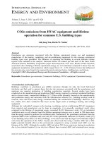
A typical installation of a downflow gas or oil furnace with a
split-system air conditioner is illustrated in Figure 3. Air enters the
furnace from the hallway (1), passing through a louvered door (2) on
the front of the furnace. The air then passes through air filters (3)
and is drawn into the top-mounted blower (4), which during the winter forces air down over the heat exchanger, where it picks up heat.
For summer cooling, the blower forces air through the furnace heat
exchanger and then through the split-system evaporator coil (5),
which removes heat and moisture from the passing air. During heating and cooling, the conditioned air then passes through a combustible floor base via a duct connector (6) before flowing into the floor
air distribution duct (7). The evaporator coil is connected via quickconnect refrigerant lines (8) to a remote air-cooled condensing unit
Residences
Fig. 3 Typical Installation of Heating and Cooling Equipment for a Manufactured Home
Fig. 3 Typical Installation of Heating and Cooling
Equipment for a Manufactured Home
(9). The condensate collected at the evaporator is drained by a flexible hose (10), routed to the exterior through the floor construction,
and connected to a suitable drain.
1.7
REFERENCES
ACCA. 1970. Selection of distribution systems. Manual G, 1st ed. Air-Conditioning Contractors of America, Washington, D.C.
ACCA. 1986. Load calculation for residential winter and summer air conditioning. Manual J, 7th ed. Air-Conditioning Contractors of America,
Washington, D.C.
ACCA. 1995. Duct design for residential winter and summer air conditioning and equipment selection. Manual D, 3rd ed. Air-Conditioning Contractors of America, Washington, D.C.
ARI. 1993. Packaged terminal air-conditioners and heat pumps. Standard
310/380-93. Air Conditioning and Refrigeration Institute, Arlington, VA.
ARI. 1993. Residential air filter equipment. Standard 680-93. Air Conditioning and Refrigeration Institute, Arlington, VA.
ARI. 1995. Sound rating of outdoor unitary equipment. Standard 270-95.
Air Conditioning and Refrigeration Institute, Arlington, VA.
ARI. 1996. Central system humidifiers for residential applications. Standard
610-96. Air Conditioning and Refrigeration Institute, Arlington, VA.
ARI. 1997. Selection, installation and servicing of residential humidifiers.
Guideline F-1997. Air Conditioning and Refrigeration Institute, Arlington, VA.
ARI. 1997. Application of sound rating levels of outdoor unitary equipment.
Standard 275-97. Air Conditioning and Refrigeration Institute, Arlington, VA.
ASHRAE. 1992. Gravimetric and dust spot procedures for testing air-cleaning devices used in general ventilation for removing particulate matter.
Standard 52.1-1992.
ASHRAE. 1992. Thermal environmental conditions for human occupancy.
Standard 55-1992.
ASHRAE. 2001. Energy-efficient design of low-rise residential buildings.
Standard 90.2-2001.
ASHRAE. 2001. Ventilation for acceptable indoor air quality. Standard 622001.
Caneta Research. 1995. Commercial institutional ground-source heat pump
engineering manual. ASHRAE.
Kavanaugh, S.P. and K. Rafferty. 1997. Ground source heat pumps—Design
of geothermal systems for commercial and institutional buildings.
ASHRAE.
CHAPTER 2
RETAIL FACILITIES
General Criteria .......................................................................
Small Stores ..............................................................................
Discount, Big-Box, and Supercenter Stores ..............................
Supermarkets ............................................................................
2.1
2.1
2.2
2.2
Department Stores .....................................................................
Convenience Centers .................................................................
Regional Shopping Centers .......................................................
Multiple-Use Complexes ...........................................................
T
HIS chapter covers design and application of air-conditioning
and heating systems for various retail merchandising facilities.
Load calculations, systems, and equipment are covered elsewhere in
the Handbook series.
offset the greater cooling and heating requirements. Entrance vestibules and heaters may be needed in cold climates.
Many new small stores are part of a shopping center. Although
exterior loads will differ between stores, internal loads will be similar; proper design is important.
GENERAL CRITERIA
Design Considerations
To apply equipment properly, the construction of the space to be
conditioned, its use and occupancy, the time of day in which greatest
occupancy occurs, physical building characteristics, and lighting
layout must be known.
The following must also be considered:
System Design. Single-zone unitary rooftop equipment is common in store air conditioning. Using multiple units to condition the
store involves less ductwork and can maintain comfort in the event
of partial equipment failure. Prefabricated and matching curbs simplify installation and ensure compatibility with roof materials.
Heat pumps, offered as packaged equipment, are readily adaptable to small-store applications and have a low first cost. Winter
design conditions, utility rates, and operating cost should be compared to those for conventional heating systems before this type of
equipment is chosen.
Water-cooled unitary equipment is available for small-store air
conditioning, but many U.S. communities restrict the use of city
water and groundwater for condensing purposes and require installation of a cooling tower. Water-cooled equipment generally operates efficiently and economically.
Retail facilities often have a high sensible heat gain relative to the
total heat gain. Unitary HVAC equipment should be designed and
selected to provide the necessary sensible heat removal.
Air Distribution. External static pressures available in smallstore air-conditioning units are limited, and ducts should be
designed to keep duct resistances low. Duct velocities should not
exceed 6 m/s and pressure drop should not exceed 0.8 Pa/m.
Average air quantities range from 47 to 60 L/s per kilowatt of
cooling in accordance with the calculated internal sensible heat
load.
Attention should be paid to suspended obstacles, such as lights
and displays, that interfere with proper air distribution.
The duct system should contain enough dampers for air balancing. Dampers should be installed in the return and outside air duct
for proper outside air/return air balance. Volume dampers should be
installed in takeoffs from the main supply duct to balance air to the
branch ducts.
Control. Controls for small stores should be kept as simple as
possible while still able to perform required functions. Unitary
equipment is typically available with manufacturer-supplied controls for easy installation and operation.
Automatic dampers should be placed in the outside air intake to
prevent outside air from entering when the fan is turned off.
Heating controls vary with the nature of the heating medium.
Duct heaters are generally furnished with manufacturer-installed
safety controls. Steam or hot-water heating coils require a motorized valve for heating control.
Time clock control can limit unnecessary HVAC operation.
Unoccupied reset controls should be provided in conjunction with
timed control.
Maintenance. To protect the initial investment and ensure maximum efficiency, maintenance of air-conditioning units in small
• Electric power—size of service
• Heating—availability of steam, hot water, gas, oil, or electricity
• Cooling—availability of chilled water, well water, city water, and
water conservation equipment
• Internal heat gains
• Rigging and delivery of equipment
• Structural considerations
• Obstructions
• Ventilation—opening through roof or wall for outside air duct,
number of doors to sales area, and exposures
• Orientation of store
• Code requirements
• Utility rates and regulations
• Building standards
Specific design requirements, such as the increase in outside air
required for exhaust where lunch counters exist, must be considered. The requirements of ASHRAE ventilation standards must be
followed. Heavy smoking and objectionable odors may necessitate
special filtering in conjunction with outside air intake and exhaust.
Load calculations should be made using the procedure outlined in
Chapter 29 of the ASHRAE Handbook—Fundamentals.
Almost all localities have some form of energy code in effect that
establishes strict requirements for insulation, equipment efficiencies, system designs, etc., and places strict limits on fenestration and
lighting. The requirements of ASHRAE Standard 90 should be met
as a minimum guideline for retail facilities.
HVAC system selection and design for retail facilities are normally determined by economics. First cost is usually the determining factor for small stores; for large retail facilities, operating and
maintenance costs are also considered. Generally, decisions about
mechanical systems for retail facilities are based on a cash flow
analysis rather than on a full life-cycle analysis.
SMALL STORES
Large glass areas found at the front of many small stores may
cause high peak solar heat gain unless they have northern exposures.
High heat loss may be experienced on cold, cloudy days. The HVAC
system for this portion of the small store should be designed to
The preparation of this chapter is assigned to TC 9.8, Large Building AirConditioning Applications.
Copyright © 2003, ASHRAE
2.5
2.6
2.6
2.7
2.1
2.2
2003 ASHRAE Applications Handbook (SI)
stores should be contracted out to a reliable service company on a
yearly basis. The contract should clearly specify responsibility for
filter replacements, lubrication, belts, coil cleaning, adjustment of
controls, compressor maintenance, replacement of refrigerant,
pump repairs, electrical maintenance, winterizing, system start-up,
and extra labor required for repairs.
Improving Operating Cost. Outside air economizers can reduce the operating cost of cooling in most climates. They are generally available as factory options or accessories with roof-mounted
units. Increased exterior insulation generally reduces operating energy requirements and may in some cases allow the size of installed
equipment to be reduced. Many codes now include minimum requirements for insulation and fenestration materials.
DISCOUNT, BIG-BOX, AND
SUPERCENTER STORES
Large warehouse or big-box stores attract customers with discount prices when large quantities are purchased. These stores typically have high-bay fixture displays and usually store merchandise
in the sales area. They feature a wide range of merchandise and may
include such diverse areas as a lunch counter, an auto service area,
a supermarket, a pharmacy, and a garden shop. Some stores sell
pets, including fish and birds. This variety of merchandise must be
considered in designing air conditioning. The design and application suggestions for small stores also apply to discount stores.
Another type of big-box facility provides both dry good and
grocery areas. The grocery area is typically treated as a traditional
stand-alone grocery (see the section on Supermarkets). Conditioning outside air for the dry goods areas must be considered to limit
the introduction of excess moisture that will migrate to the freezer
aisles.
Hardware, lumber, furniture, etc., is also sold in big-box facilities. A particular concern in this type of facility is ventilation for
material-handling equipment, such as forklift trucks.
In addition, areas such as stockrooms, rest rooms, offices, and
special storage rooms for perishable merchandise may require air
conditioning or refrigeration.
Load Determination
Operating economics and the spaces served often dictate inside
design conditions. Some stores may base summer load calculations
on a higher inside temperature (e.g., 27ºC db) but then set the thermostats to control at 22 to 24ºC db. This reduces the installed equipment size while providing the desired inside temperature most of the
time.
Special rooms for storage of perishable goods are usually
designed with separate unitary air conditioners.
The heat gain from lighting will not be uniform throughout the
entire area. For example, jewelry and other specialty displays typically have lighting heat gains of 65 to 85 W per square meter of floor
area, whereas the typical sales area has an average value of 20 to
40 W/m2. For stockrooms and receiving, marking, toilet, and rest
room areas, a value of 20 W/m2 may be used. When available, actual
lighting layouts rather than average values should be used for load
computation.
The store owner usually determines the population density for a
store based on its location, size, and past experience.
Food preparation and service areas in discount and outlet stores
range from small lunch counters with heat-producing equipment
(ranges, griddles, ovens, coffee urns, toasters) in the conditioned
space to large deluxe installations with kitchens separate from the
conditioned space. Chapter 31 has specific information on HVAC
systems for kitchen and eating spaces.
Data on the heat released by special merchandising equipment,
such as amusement rides for children or equipment used for preparing speciality food items (e.g., popcorn, pizza, frankfurters,
hamburgers, doughnuts, roasted chickens, cooked nuts, etc.), should
be obtained from the equipment manufacturers.
Ventilation and outside air must be provided as required in
ASHRAE Standard 62 and local codes.
Design Considerations
Heat released by installed lighting is usually sufficient to offset the design roof heat loss. Therefore, interior areas of these
stores need cooling during business hours throughout the year.
Perimeter areas, especially the storefront and entrance areas, may
have highly variable heating and cooling requirements. Proper
zone control and HVAC design are essential. The location of
checkout lanes in this area makes proper environmental control
even more important.
System Design. The important factors in selecting discount and
outlet store air-conditioning systems are (1) installation costs, (2)
floor space required for equipment, (3) maintenance requirements
and equipment reliability, and (4) simplicity of control. Roofmounted units are most commonly used.
Air Distribution. The air supply for large sales areas should
generally be designed to satisfy the primary cooling requirement.
For perimeter areas, the variable heating and cooling requirements
must be considered.
Because these stores require high, clear areas for display and
restocking, air is generally distributed from heights of 4.3 m and
greater. Air distribution at these heights requires high velocities in
the heating season to overcome the buoyancy of hot air. The discharge air velocity creates turbulence in the space and induces airflow from the ceiling area to promote complete mixing of the air.
During the cooling season the designer can take advantage of
stratification to reduce equipment load. By introducing air near customers at low velocity, the air will stratify during the cooling season.
With this method of air distribution, the set-point temperature can
be maintained in the occupant zone and the temperature in the upper
space can be allowed to rise. However, this strategy requires equipment to destratify the air during the heating season. Space-mounted
fans, and radiant heating at the perimeter, entrance, and sales areas
may be required.
Control. Because the controls are usually operated by personnel who have little knowledge of air conditioning, systems should
be simple, dependable, and fully automatic, as simple to operate as
a residential system. Most unitary equipment has automatic electronic controls for ease of operation.
Maintenance. Most stores do not employ trained maintenance
personnel; they rely instead on service contracts with either the
installer or a local service company. For suggestions on lowering
operating costs, see the section on Small Stores.
SUPERMARKETS
Load Determination
Heating and cooling loads should be calculated using the methods outlined in Chapter 29 of the ASHRAE Handbook—Fundamentals. Data for calculating loads caused by people, lights, motors, and
heat-producing equipment should be obtained from the store owner
or manager or from the equipment manufacturer. In supermarkets,
space conditioning is required both for human comfort and for
proper operation of refrigerated display cases. The air-conditioning
unit should introduce a minimum quantity of outside air, either the
volume required for ventilation based on ASHRAE Standard 62 or
the volume required to maintain slightly positive pressure in the
space, whichever is larger.
Many supermarkets are units of a large chain owned or operated
by a single company. The standardized construction, layout, and
equipment used in designing many similar stores simplify load
calculations.
Retail Facilities
Fig. 1 Refrigerated Case Load Variation with Store
Air Humidity
2.3
Table 1
Refrigerating Effect (RE) Produced by Open
Refrigerated Display Fixtures
RE on Building Per Unit Length of Fixture*
Display Fixture Types
Fig. 1
Refrigerated Case Load Variation with Store
Air Humidity
It is important that the final air-conditioning load be correctly
determined. Refer to manufacturers’ data for information on total
heat extraction, sensible heat, latent heat, and percentage of latent to
total loadfor display cases. Engineers report considerable fixture
heat removal (case load) variation as the relative humidity and
temperature vary in comparatively small increments. Relative
humidity above 55% (24°C and 10.3 g/kg absolute humidity) substantially increases the load; reduced absolute humidity substantially decreases the load, as shown in Figure 1. Trends in store
design, which include more food refrigeration and more efficient
lighting, reduce the sensible component of the load even further.
To calculate the total load and percentage of latent and sensible
heat that the air conditioning must handle, the refrigerating effect
imposed by the display fixtures must be subtracted from the building’s gross air-conditioning requirements (Table 1).
Modern supermarket designs have a high percentage of closed
refrigerated display fixtures. These vertical cases have large glass
display doors and greatly reduce the problem of latent and sensible
heat removal from the occupied space. The doors do, however,
require heaters to minimize condensation and fogging. These heaters should cycle by automatic control.
For more information on supermarkets, see Chapter 47, Retail
Food Store Refrigeration and Equipment, in the ASHRAE Handbook—Refrigeration.
Design Considerations
Store owners and operators frequently complain about cold
aisles, heaters that operate even when the outside temperature is
above 21ºC, and air conditioners that operate infrequently. These
problems are usually attributed to spillover of cold air from open
refrigerated display equipment.
Although refrigerated display equipment may cause cold stores,
the problem is not excessive spillover or improperly operating
equipment. Heating and air-conditioning systems must compensate
for the effects of open refrigerated display equipment. Design considerations include the following:
• Increased heating requirement because of removal of large quantities of heat, even in summer.
Latent
Heat,
W/m
% Latent Sensible
to Total
Heat,
RE
W/m
Total
RE,
W/m
Low-temperature (frozen food)
Single-deck
36
Single-deck/double-island
67
2-deck
138
3-deck
310
4- or 5-deck
384
15
15
20
20
20
199
384
554
1238
1538
235
451
692
1548
1922
Ice cream
Single-deck
Single-deck/double-island
62
67
15
15
352
384
414
451
50
211
188
15
20
20
286
842
754
336
1053
942
35
184
15
20
196
738
231
922
Standard-treatment
Meats
Single-deck
Multideck
Dairy, multideck
Produce
Single-deck
Multideck
*These figures are general magnitudes for fixtures adjusted for average desired product
temperatures and apply to store ambients in front of display cases of 22.2 to 23.3°C
with 50 to 55% rh. Raising the dry bulb only 2 to 3 K and the humidity to 5 to 10% can
increase loads (heat removal) 25% or more. Lower temperatures and humidities, as in
winter, have an equally marked effect on lowering loads and heat removal from the
space. Consult display case manufactuer’s data for the particular equipment to be used.
• Net air-conditioning load after deducting the latent and sensible
refrigeration effect. The load reduction and change in sensiblelatent load ratio have a major effect on equipment selection.
• Need for special air circulation and distribution to offset the heat
removed by open refrigerating equipment.
• Need for independent temperature and humidity control.
Each of these problems is present to some degree in every supermarket, although situations vary with climate and store layout.
Methods of overcoming these problems are discussed in the following sections. Energy costs may be extremely high if the year-round
air-conditioning system has not been designed to compensate for
the effects of refrigerated display equipment.
Heat Removed by Refrigerated Displays. The display refrigerator not only cools a displayed product but envelops it in a blanket
of cold air that absorbs heat from the room air in contact with it.
Approximately 80 to 90% of the heat removed from the room by
vertical refrigerators is absorbed through the display opening. Thus,
the open refrigerator acts as a large air cooler, absorbing heat from
the room and rejecting it via the condensers outside the building.
Occasionally, this conditioning effect can be greater than the design
air-conditioning capacity of the store. The heat removed by the
refrigeration equipment must be considered in the design of the airconditioning and heating systems because this heat is being
removed constantly, day and night, summer and winter, regardless
of the store temperature.
Display cases increase the building heating requirement such
that heat is often required at unexpected times. The following
example illustrates the extent of this cooling effect. The desired
store temperature is 24ºC. Store heat loss or gain is assumed to be
8 kW/ºC of temperature difference between outside and store
temperature. (This value varies with store size, location, and
exposure.) The heat removed by refrigeration equipment is
56 kW. (This value varies with the number of refrigerators.) The
latent heat removed is assumed to be 19% of the total, leaving
81% or 45.4 kW sensible heat removed, which will cool the store
45.4/8 = 5.7ºC. By constantly removing sensible heat from its
2.4
environment, the refrigeration equipment in this store will cool
the store 5.7ºC below outside temperature in winter and in summer. Thus, in mild climates, heat must be added to the store to
maintain comfort conditions.
The designer can either discard or reclaim the heat removed by
refrigeration. If economics and store heat data indicate that the heat
should be discarded, heat extraction from the space must be
included in the heating load calculation. If this internal heat loss is
not included, the heating system may not have sufficient capacity to
maintain design temperature under peak conditions.
The additional sensible heat removed by the cases may change
the air-conditioning latent load ratio from 32% to as much as 50%
of the net heat load. Removing a 50% latent load by refrigeration
alone is very difficult. Normally, it requires specially designed
equipment with reheat or chemical adsorption.
Multishelf refrigerated display equipment requires 55% rh or
less. In the dry-bulb temperature ranges of average stores, humidity
in excess of 55% can cause heavy coil frosting, product zone frosting in low-temperature cases, fixture sweating, and substantially
increased refrigeration power consumption.
A humidistat can be used during summer cooling to control
humidity by transferring heat from the condenser to a heating coil in
the airstream. The store thermostat maintains proper summer temperature conditions. Override controls prevent conflict between the
humidistat and the thermostat.
The equivalent result can be accomplished with a conventional
air-conditioning system by using three- or four-way valves and
reheat condensers in the ducts. This system borrows heat from the
standard condenser and is controlled by a humidistat. For higher
energy efficiency, specially designed equipment should be considered. Desiccant dehumidifiers and heat pipes have also been used.
Humidity. Cooling from refrigeration equipment does not preclude the need for air conditioning. On the contrary, it increases the
need for humidity control.
With increases in store humidity, heavier loads are imposed on
the refrigeration equipment, operating costs rise, more defrost periods are required, and the display life of products is shortened. The
dew point rises with relative humidity, and sweating can become so
profuse that even nonrefrigerated items such as shelving superstructures, canned products, mirrors, and walls may sweat.
Lower humidity results in lower operating costs for refrigerated
cases. There are three methods to reduce the humidity level: (1)
standard air conditioning, which may overcool the space when the
latent load is high and sensible load is low; (2) mechanical dehumidification, which removes moisture by lowering the air temperature to its dew point, and uses hot-gas reheat when needed to
discharge at any desired temperature; and (3) desiccant dehumidification, which removes moisture independent of temperature, supplying warm air to the space unless postcooling is provided to
discharge at any desired temperature.
Each method provides different dew-point temperatures at different energy consumption and capital expenditures. The designer
should evaluate and consider all consequential tradeoffs. Standard
air conditioning requires no additional investment but reduces the
space dew-point temperature only to 16 to 18°C. At 24°C space
temperature this results in 60 to 70% rh at best. Mechanical dehumidifiers can provide humidity levels of 40 to 50% at 24°C. Supply
air temperature can be controlled with hot-gas reheat between 10
and 32°C. Desiccant dehumidification can provide levels of 35 to
40% rh at 24°C. Postcooling supply air may be required, depending
on internal sensible loads. A desiccant is reactivated by passing hot
air at 80 to 121ºC through the desiccant base.
System Design. The same air-handling equipment and distribution system are generally used for both cooling and heating.
The entrance area is the most difficult section to heat. Many
supermarkets in the northern United States are built with vestibules provided with separate heating equipment to temper the
2003 ASHRAE Applications Handbook (SI)
cold air entering from outside. Auxiliary heat may also be provided at the checkout area, which is usually close to the front
entrance. Methods of heating entrance areas include the use of
(1) air curtains, (2) gas-fired or electric infrared radiant heaters,
and (3) waste heat from the refrigeration condensers.
Air-cooled condensing units are the most commonly used in
supermarkets. Typically, a central air handler conditions the
entire sales area. Specialty areas like bakeries, computer rooms,
or warehouses are better served with a separate air handler
because the loads in these areas vary and require different control
than the sales area.
Most installations are made on the roof of the supermarket.
If air-cooled condensers are located on the ground outside the
store, they must be protected against vandalism as well as truck
and customer traffic. If water-cooled condensers are used on the
air-conditioning equipment and a cooling tower is required,
provisions should be made to prevent freezing during winter
operation.
Air Distribution. Designers overcome the concentrated load at
the front of a supermarket by discharging a large portion of the
total air supply into the front third of the sales area.
The air supply to the space with a standard air-conditioning
system is typically 5 L/s per square metre of sales area. This value
should be calculated based on the sensible and latent internal
loads. The desiccant system typically requires less air supply
because of its high moisture removal rate, typically 2.5 L/s per
square metre. Mechanical dehumidification can fall within these
parameters, depending on required dew point and suction pressure
limitations.
Being denser, air cooled by the refrigerators settles to the floor
and becomes increasingly colder, especially in the first 900 mm
above the floor. If this cold air remains still, it causes discomfort
and does not help to cool other areas of the store that need more
cooling. Cold floors or areas in the store cannot be eliminated by
the simple addition of heat. Reduction of air-conditioning capacity without circulation of localized cold air is analogous to
installing an air conditioner without a fan. To take advantage of
the cooling effect of the refrigerators and provide an even temperature in the store, the cold air must be mixed with the general
store air.
To accomplish the necessary mixing, air returns should be
located at floor level; they should also be strategically placed to
remove the cold air near concentrations of refrigerated fixtures.
Returns should be designed and located to avoid creating drafts.
There are two general solutions to this problem:
• Return Ducts in Floor. This is the preferred method and can be
accomplished in two ways. The floor area in front of the refrigerated display cases is the coolest area. Refrigerant lines are run to
all of these cases, usually in tubes or trenches. If the trenches or
tubes are enlarged and made to open under the cases for air return,
air can be drawn in from the cold area (Figure 2). The air is
returned to the air-handling unit through a tee connection to the
trench before it enters the back room area. The opening through
which the refrigerant lines enter the back room should be sealed.
If refrigerant line conduits are not used, air can be returned
through inexpensive underfloor ducts. If refrigerators have
insufficient undercase air passage, the manufacturer should be
consulted. Often they can be raised off the floor approximately
40 mm. Floor trenches can also be used as ducts for tubing,
electrical supply, and so forth.
Floor-level return relieves the problem of localized cold areas
and cold aisles and uses the cooling effect for store cooling, or
increases the heating efficiency by distributing the air to areas
that need it most.
• Fans Behind Cases. If ducts cannot be placed in the floor,
circulating fans can draw air from the floor and discharge it above
Retail Facilities
2.5
Fig. 2 Floor Return Ducts
Fig. 2
Floor Return Ducts
Fig. 3 Air Mixing Using Fans Behind Cases
Fig. 3
Fig. 4
Air Mixing Using Fans Behind Cases
Heat Reclaiming Systems
Fig. 5 Machine Room with Automatic Temperature Control Interlocked with Store Temperature Control
Fig. 5 Machine Room with Automatic Temperature
Control Interlocked with Store Temperature Control
for heat recovery applications are more complex and should be
coordinated with the equipment manufacturer.
Maintenance and Heat Reclamation. Most supermarkets,
except large chains, do not employ trained maintenance personnel,
but rather rely on service contracts with either the installer or a local
service company. This relieves store management of the responsibility of keeping the air conditioning operating properly.
Heat extracted from the store and heat of compression may be
reclaimed for heating cost saving. One method of reclaiming
rejected heat is to use a separate condenser coil located in the air
conditioner’s air handler, either alternately or in conjunction with
the main refrigeration condensers, to provide heat as required (Figure 4). Another system uses water-cooled condensers and delivers
its rejected heat to a water coil in the air handler.
The heat rejected by conventional machines using air-cooled
condensers may be reclaimed by proper duct and damper design
(Figure 5). Automatic controls can either reject this heat to the outside or recirculate it through the store.
DEPARTMENT STORES
Department stores vary in size, type, and location, so air-conditioning design should be specific to each store. An ample minimum quantity of outside air reduces or eliminates odor problems.
Essential features of a quality system include (1) an automatic control system properly designed to compensate for load fluctuations,
(2) zoned air distribution to maintain uniform conditions under
shifting loads, and (3) use of outside air for cooling during intermediate seasons and peak sales periods. It is also desirable to
adjust inside temperature for variations in the outside temperature.
Although close control of humidity is not necessary, a properly
designed system should operate to maintain relative humidity at
50% or below with a corresponding dry-bulb temperature of 26ºC.
This humidity limit eliminates musty odors and retards perspiration, particularly in fitting rooms.
Load Determination
Fig. 4
Heat Reclaiming Systems
the cases (Figure 3). Although this approach prevents objectionable cold aisles in front of the refrigerated display cases, it does
not prevent an area with a concentration of refrigerated fixtures
from remaining colder than the rest of the store.
Control. Store personnel should only be required to change the
position of a selector switch to start or stop the system or to change
from heating to cooling or from cooling to heating. Control systems
Because the occupancy (except store personnel) is transient, inside conditions are commonly set not to exceed 26ºC db and 50% rh
at outside summer design conditions, and 21ºC db at outside winter
design conditions. Winter humidification is seldom used in store air
conditioning.
The number of customers and store personnel normally found
on each conditioned floor must be ascertained, particularly in specialty departments or other areas having a greater-than-average
concentration of occupants. Lights should be checked for wattage
and type. Table 2 gives approximate values for lighting in various
areas; Table 3 gives approximate occupancies.
2.6
Table 2
2003 ASHRAE Applications Handbook (SI)
Approximate Lighting Load for Department Stores
W/m2
Area
Basement
First floor
Upper floors, women’s wear
Upper floors, house furnishings
Table 3
30 to 50
40 to 70
30 to 50
20 to 30
Approximate Occupancy for Department Stores
Area
Basement
First floor
Upper floors, women’s wear
house furnishings
m2 per person
2 to 9
2 to 7
5 to 9
9 or more
Other loads, such as those from motors, beauty parlor and restaurant equipment, and any special display or merchandising equipment, should be determined.
The minimum outside air requirement should be as defined in
ASHRAE Standard 62, which is generally acceptable and adequate
for removing odors and keeping thebuilding atmosphere fresh.
However, local ventilation ordinances may require greater quantities of outside air.
Paint shops, alteration rooms, rest rooms, eating places, and
locker rooms should be provided with positive exhaust ventilation,
and their requirements must be checked against local codes.
Design Considerations
Before performing load calculations, the designer should examine the store arrangement to determine what will affect the load and
the system design. For existing buildings, actual construction, floor
arrangement, and load sources can be surveyed. For new buildings,
examination of the drawings and discussion with the architect or
owner is required.
Larger stores may contain beauty parlors, restaurants, lunch
counters, or auditoriums. These special areas may operate during all
store hours. If one of these areas has a load that is small in proportion to the total load, the load may be met by the portion of the air
conditioning serving that floor. If present or future operation could
for any reason be compromised by such a strategy, this space should
be served by separate air conditioning. Because of the concentrated
load in the beauty parlor, separate air distribution should be provided for this area.
The restaurant, because of its required service facilities, is generally centrally located. It is often used only during lunchtime. For
odor control, a separate air-handling system should be considered.
Future plans for the store must be ascertained because they can
have a great effect on the type of air conditioning and refrigeration
to be used.
System Design. Air conditioning for department stores may be
unitary or central station. Selection should be based on owning and
operating costs as well as special considerations for the particular
store, such as store hours, load variations, and size of load.
Large department stores often use central-station systems consisting of air-handling units having chilled-water cooling coils,
hot-water heating coils, fans, and filters. Air systems must have
adequate zoning for varying loads, occupancy, and usage. Wide
variations in people loads may justify considering variable-volume
air distribution systems. Water chilling and heating plants distribute
water to the various air handlers and zones and may take advantage
of some load diversity throughout the building.
Air-conditioning equipment should not be placed in the sales
area; instead, it should be located in ceiling, roof, and mechanical
equipment room areas whenever practicable. Maintenance and
operation after installation should be considered when siting
equipment.
Air Distribution. All buildings must be studied for orientation, wind exposure, construction, and floor arrangement. These
factors affect not only load calculations, but also zone arrangements and duct locations. In addition to entrances, wall areas with
significant glass, roof areas, and population densities, the
expected locations of various departments (e.g., the lamp department) should be considered. Flexibility must be left in the duct
design to allow for future movement of departments. The preliminary duct layout should also be checked in regard to winter heating to determine any special situations. It is usually necessary to
design separate air systems for entrances, particularly in northern
areas. This is also true for storage areas where cooling is not contemplated.
Air curtains may be installed at entrance doorways to limit or
prevent infiltration of unconditioned air, at the same time providing
greater ease of entry compared to a vestibule with a second set of
doors.
Control. The necessary extent of automatic control depends on
the type of installation and the extent to which it is zoned. Control
must be such that correctly conditioned air is delivered to each zone.
Outside air intake should be automatically controlled to operate at
minimum cost while providing required airflow. Partial or full automatic control should be provided for cooling to compensate for load
fluctuations. Completely automatic refrigeration plants should be
considered.
Maintenance. Most department stores employ personnel for
routine operation and maintenance, but rely on service and preventive maintenance contracts for refrigeration cycles, chemical treatment, central plant systems, and major repairs.
Improving Operating Cost. An outside air economizer can
reduce the operating cost of cooling in most climates. These are
generally available as factory options or accessories with the airhandling units or control systems. Heat recovery and thermal storage should also be analyzed.
CONVENIENCE CENTERS
Many small stores, discount stores, supermarkets, drugstores,
theaters, and even department stores are located in convenience
centers. The space for an individual store is usually leased. Arrangements for installing air conditioning in leased space vary.
Typically, the developer builds a shell structure and provides the
tenant with an allowance for usual heating and cooling and other
minimum interior finish work. The tenant must then install an
HVAC system. In another arrangement, developers install HVAC
units in the small stores with the shell construction, often before the
space is leased or the occupancy is known. Larger stores typically
provide their own HVAC design and installation.
Design Considerations
The developer or owner may establish standards for typical heating and cooling that may or may not be sufficient for the tenant’s
specific requirements. The tenant may therefore have to install systems of different sizes and types than originally allowed for by the
developer. The tenant must ascertain that power and other services
will be available for the total intended requirements.
The use of party walls in convenience centers tends to reduce
heating and cooling loads. However, the effect an unoccupied adjacent space has on the partition load must be considered.
REGIONAL SHOPPING CENTERS
Regional shopping centers generally incorporate an enclosed,
heated and air-conditioned mall. These centers are normally owned
by a developer, who may be an independent party, a financial institution, or one of the major tenants in the center.
Retail Facilities
2.7
Table 4 Typical Installed Cooling Capacity
and Lighting Levels—Midwestern United States
Type of Space
Dry retailb
Restaurant
Fast food
food court tenant area
food court seating area
Mall common area
Total
Area per
Unit of
Installed
Cooling
m2/kW
Installed
Cooling
per Unit
of Area,
W/m2
Lighting
Density
of Area,
W/m2
Annual
Lighting
Energy
Use,a
kWh/m2
9.69
3.59
104.1
277.6
43.1
21.5
174.4
87.2
4.23
3.88
7.61
6.97
236.6
258.7
135.6
142.0
32.3
32.3
32.3
38.8
131.3
131.3
131.3c
157.2
Source: Based on 2001 Data—Midwestern United States.
aHours of operating lighting assumes 12 h/day and 6.5 days/week.
bJewelry, high-end lingerie, and some other lighting levels are typically 65 to 85 120
W/m2 and can range to 120 W/m2.
c62.4 kWh/m2 for centers that shut off lighting during daylight, assuming 6 h/day and
6.2 days/week.
Major department stores are typically considered separate buildings, although they are attached to the mall. The space for individual
small stores is usually leased. Arrangements for installing air conditioning in the individually leased spaces vary, but are similar to
those for small stores in convenience centers.
Table 4 presents typical data that can be used as check figures and
field estimates. However, this table should not be used for final
determination of load, because the values are only averages.
Design Considerations
The owner provides the air-conditioning system for the
enclosed mall. The mall may use a central plant or unitary equipment. The owner generally requires that the individual tenant
stores connect to a central plant and includes charges for heating
and cooling in the rent. Where unitary systems are used, the
owner generally requires that the individual tenant install a unitary system of similar design.
The owner may establish standards for typical heating and cooling systems that may or may not be sufficient for the tenant’s specific requirements. Therefore, the tenant may have to install systems
of different sizes than originally allowed for by the developer.
Leasing arrangements may include provisions that have a detrimental effect on conservation (such as allowing excessive lighting and outside air or deleting requirements for economizer
systems). The designer of HVAC for tenants in a shopping center
must be well aware of the lease requirements and work closely
with leasing agents to guide these systems toward better energy
efficiency.
Many regional shopping centers contain specialty food court
areas that require special considerations for odor control, outside air
requirements, kitchen exhaust, heat removal, and refrigeration
equipment.
System Design. Regional shopping centers vary widely in physical arrangement and architectural design. Single-level and smaller
centers usually use unitary systems for mall and tenant air conditioning; multilevel and larger centers usually use a central plant. The
owner sets the design of the mall and generally requires that similar
systems be installed for tenant stores.
A typical central plant may distribute chilled air to individual
tenant stores and to the mall air-conditioning system and use
variable-volume control and electric heating at the local use point.
Some plants distribute both hot and chilled water. Some all-air systems also distribute heated air. The central plant provides improved
efficiency and better overall economics of operation. Central plants
also provide the basic components required for smoke control.
Air Distribution. Air distribution for individual stores should be
designed for a particular space occupancy. Some tenant stores maintain a negative pressure relative to the mall for odor control.
Air distribution should maintain a slight positive pressure relative to atmospheric pressure and a neutral pressure relative to most
of the individual tenant stores. Exterior entrances should have vestibules with independent heating systems.
Smoke management is required by many building codes, so air
distribution should be designed to easily accommodate smoke control requirements.
Maintenance. Methods for ensuring the operation and maintenance of HVAC systems in regional shopping centers are similar to
those used in department stores. Individual tenant stores may have
to provide their own maintenance.
Improving Operating Cost. Methods for lowering operating
costs in shopping centers are similar to those used in department
stores. Some shopping centers have successfully used cooling tower
heat exchanger economizers.
Central plant systems for regional shopping centers typically
have much lower operating costs than unitary systems. However, the
initial cost of the central plant system is typically higher.
MULTIPLE-USE COMPLEXES
Multiple-use complexes are being developed in most metropolitan
areas. These complexes generally combine retail facilities with other
facilities such as offices, hotels, residences, or other commercial space
into a single site. This consolidation of facilities into a single site or
structure provides benefits such as improved land use; structural savings; more efficient parking; utility savings; and opportunities for
more efficient electrical, fire protection, and mechanical systems.
Load Determination
The various occupancies may have peak HVAC demands that
occur at different times of the day or even of the year. Therefore, the
HVAC loads of these occupancies should be determined independently. Where a combined central plant is considered, a block load
should also be determined.
Design Considerations
Retail facilities are generally located on the lower levels of
multiple-use complexes, and other commercial facilities are on
upper levels. Generally, the perimeter loads of the retail portion
differ from those of the other commercial spaces. Greater lighting and population densities also make HVAC demands for the
retail space different from those for the other commercial space.
The differences in HVAC characteristics for various occupancies
within a multiple-use complex indicate that separate air handling and
distribution should be used for the separate spaces. However, combining the heating and cooling requirements of various facilities into
a central plant can achieve a substantial saving. A combined central
heating and cooling plant for a multiple-use complex also provides
good opportunities for heat recovery, thermal storage, and other similar functions that may not be economical in a single-use facility.
Many multiple-use complexes have atriums. The stack effect created by atriums requires special design considerations for tenants and
space on the main floor. Areas near entrances require special measures to prevent drafts and accommodate extra heating requirements.
System Design. Individual air-handling and distribution systems
should be designed for the various occupancies. The central heating
and cooling plant may be sized for the block load requirements,
which may be less than the sum of each occupancy’s demand.
Control. Multiple-use complexes typically require centralized
control. It may be dictated by requirements for fire and smoke control, security, remote monitoring, billing for central facilities use,
maintenance control, building operations control, and energy management.
CHAPTER 3
COMMERCIAL AND PUBLIC BUILDINGS
General Criteria ............................................................................................................................. 3.1
Dining and Entertainment Centers ................................................................................................ 3.4
Office Buildings .............................................................................................................................. 3.6
Bowling Centers ............................................................................................................................. 3.8
Communication Centers ................................................................................................................. 3.9
Transportation Centers .................................................................................................................. 3.9
Warehouses ................................................................................................................................... 3.11
T
HIS chapter summarizes load characteristics and both general
and specific design criteria that apply to commercial buildings.
Design criteria include such factors as comfort level; cost; and fire,
smoke, and odor control. Specific information is included on dining
and entertainment centers, office buildings, bowling centers, communication centers, transportation centers, and warehouses. Museums, libraries, and archives are covered in Chapter 21.
Load Characteristics
Load characteristics for the building must be understood to
ensure that systems respond adequately at part load as well as at
full load. Systems must be capable of responding to load fluctuations based on the combination of occupancy variations, process
load shifts, solar load variations, and atmospheric weather conditions (e.g., temperature and humidity changes). Some building
loads may be brief and infrequent, such as an annual meeting of a
large group in a conference room, whereas others may be more
constant and long-lasting, such as operation of data processing
equipment.
Analysis of any building for heat recovery or total energy systems requires sufficient load profile and load duration information
on all forms of building input to (1) properly evaluate the instantaneous effect of one on the other when no energy storage is contemplated and (2) evaluate short-term effects (up to 48 h) when energy
storage is used.
Load profile curves consist of appropriate energy loads plotted
against the time of day. Load duration curves indicate the accumulated number of hours at each load condition, from the highest to the
lowest load for a day, a month, or a year. The area under load profile
and load duration curves for corresponding periods is equivalent to
the load multiplied by the time. These calculations must consider
the type of air and water distribution systems in the building.
Load profiles for two or more energy forms during the same
operating period may be compared to determine load-matching
characteristics under diverse operating conditions. For example,
when thermal energy is recovered from a diesel-electric generator at
a rate equal to or less than the thermal energy demand, the energy
can be used instantaneously, avoiding waste. It may be worthwhile
to store thermal energy when it is generated at a greater rate than
demanded. A load profile study helps determine the economics of
thermal storage.
Similarly, with internal source heat recovery, load matching must
be integrated over the operating season with the aid of load duration
curves for overall feasibility studies. These curves are useful in
energy consumption analysis calculations as a basis for hourly input
values in computer programs (see Chapter 31 of the ASHRAE Handbook—Fundamentals).
Aside from environmental considerations, the economic feasibility of district heating and cooling is influenced by load density and
diversity factors for branch feeds to buildings along distribution
mains. For example, the load density or energy per unit length of
distribution main can be small enough in a complex of low-rise,
lightly loaded buildings located at a considerable distance from one
another, to make a central heating, cooling, or heating and cooling
plant uneconomical.
Concentrations of internal loads peculiar to each application are
covered later in this chapter and in Chapters 28, 29, and 30 of the
ASHRAE Handbook—Fundamentals.
GENERAL CRITERIA
In theory, most systems, if properly applied, can be successful in
any building. However, in practice, such factors as initial and operating costs, space allocation, architectural design, location, and the
engineer’s evaluation and experience limit the proper choices for a
given building type.
Heating and air-conditioning systems that are simple in design
and of the proper size for a given building generally have fairly low
maintenance and operating costs. For optimum results, as much
inherent thermal control as is economically possible should be built
into the basic structure. The relationship between the shape, orientation, and air-conditioning capacity of a building should also be
considered. Because the exterior load may vary from 30 to 60% of
the total air-conditioning load when the fenestration area ranges
from 25 to 75% of the exterior envelope surface area, it may be
desirable to minimize the perimeter area. For example, a rectangular
building with a four-to-one aspect ratio requires substantially more
refrigeration than a square building with the same floor area.
Building size, shape, and component selection are normally
determined by the building architect and/or owner. Changing any of
these parameters to reach optimum results requires cooperation
among these individuals or groups.
Proper design also considers controlling noise and minimizing
pollution of the atmosphere and water systems around the building.
Retrofitting existing buildings is also an important part of the
construction industry because of increased costs of construction
and the necessity of reducing energy consumption. Table 1 lists
factors to consider before selecting a system for any building. The
selection is often made by the owner and may not be based on an
engineering study. To a great degree, system selection is based on
the engineer’s ability to relate factors involving higher first cost or
lower life-cycle cost and benefits that have no calculable monetary
value.
Some buildings are constructed with only heating and ventilating
systems. For these buildings, greater design emphasis should be
placed on natural or forced ventilation systems to minimize occupant discomfort during hot weather. To provide for future cooling,
humidification, or both, the design principles are the same as those
for a fully air-conditioned building.
The preparation of this chapter is assigned to TC 9.8, Large Building AirConditioning Applications.
Copyright © 2003, ASHRAE
3.1
3.2
2003 ASHRAE Applications Handbook (SI)
Table 1
General Design Criteriaa, b
Inside Design Conditions
General Category
Dining
and
Entertainment
Centers
Winter
Cafeterias and
Luncheonettes
21 to 23°C
20 to 30% rh
26°C d
50% rh
0.25 m/s at 1.8 m
above floor
12 to 15
Restaurants
21 to 23°C
20 to 30% rh
23 to 26°C
55 to 60% rh
0.13 to 0.15 m/s
8 to 12
Bars
21 to 23°C
20 to 30% rh
23 to 26°C
50 to 60% rh
0.15 m/s at 1.8 m
above floor
15 to 20
Nightclubs and
Casinos
21 to 23°C
20 to 30% rh
23 to 26°C
50 to 60% rh
below 0.13 m/s at
1.5 m above floor
20 to 30
Kitchens
21 to 23°C
29 to 31°C
0.15 to 0.25 m/s
12 to 15g
21 to 23°C
20 to 30% rh
23 to 26°C
50 to 60% rh
0.13 to 0.23 m/s
4 to 10 L/(s·m2)
4 to 10
Office
Buildings
Summer
20 to 22°C
40 to 55% rh
Average
Libraries
and
Museums
See Chapter 21, Museums,
Libraries, and Archives
Archival
Bowling
Centers
Air Movement
Circulation,
air changes per hour
Specific Category
below 0.13 m/s
below 0.13 m/s
8 to 12
8 to 12
21 to 23°C
20 to 30% rh
24 to 26°C
50 to 55% rh
0.25 m/s at 1.8 m
above floor
10 to 15
Telephone
Terminal Rooms
22 to 26°C
40 to 50% rh
22 to 26°C
40 to 50% rh
0.13 to 0.15 m/s
Radio and
Television Studios
21 to 23°C
40 to 50% rh
23 to 26°C
45 to 55% rh
0.13 to 0.15 m/s
Airport
Terminals
23 to 26°C
30 to 40% rh
23 to 26°C
40 to 55% rh
below 0.13 m/s at
3.7 m above floor
8 to 12
Ship
Docks
21 to 23°C
20 to 30% rh
23 to 26°C
50 to 60% rh
0.13 to 0.15 m/s at
1.8 m above floor
8 to 12
Bus
Terminals
21 to 23°C
20 to 30% rh
23 to 26°C
50 to 60% rh
0.13 to 0.15 m/s at
1.8 m above floor
8 to 12
Garagesj
4 to 13°C
27 to 38°C
0.15 to 0.38 m/s
8 to 20
Communication
Centers
15 to 40
Transportation
Centers
Warehouses
Inside design temperatures for warehouses
often depend on the materials stored.
4 to 6
Refer to NFPA
1 to 4
Commercial and Public Buildings
Table 1
Noisec
3.3
General Design Criteriaa, b (Concluded)
Filtering Efficiencies (ASHRAE Standard 52.1)
Load Profile
Comments
Peak at 1 to 2 P.M.
NC 40 to
50 e
Prevent draft discomfort for patrons waiting
in serving lines
35% or better
Peak at 1 to 2 P.M.
NC 35 to 40
35% or better
NC 35 to 50
Use charcoal for odor control with manual purge control
for 100% outside air to exhaust ±35% prefilters
NC 35 to 45 f
Use charcoal for odor control with manual purge control
for 100% outside air to exhaust ±35% prefilters
NC 40 to 50
10 to 15% or better
Peak at 5 to 7 P.M.
Nightclubs peak at 8 P.M. to
Provide good air movement but prevent cold
2 A.M. Casinos peak at 4 P.M. to
draft discomfort for patrons
2 A.M. Equipment, 24 h/day
Negative air pressure required for odor
control. (See also Chapter 31, Kitchen
Ventilation.)
Peak at 4 P.M.
NC 30 to 45
35 to 60% or better
Peak at 3 P.M.
NC 35 to 40
35 to 60% or better
Peak at 3 P.M.
NC 35
35% prefilters plus charcoal filters
85 to 95% final i
Peak at 6 to 8 P.M.
NC 40 to 50
10 to 15%
to NC 60
85% or better
Varies with location and use
Constant temperature and humidity required
NC 15 to 25
35% or better
Varies widely due to changes in
Constant temperature and humidity required
lighting and people
NC 35 to 50
35% or better
and charcoal filters
Peak at 10 A.M. to 9 P.M.
Positive air pressure required in terminal
Peak at 10 A.M. to 5 P.M.
NC 35 to 50
10 to 15%
NC 35 to 50
35% with exfiltration
NC 35 to 50
10 to 15%
to NC 75
10 to 35%
Positive air pressure required in waiting area
Peak at 10 A.M. to 5 P.M.
Positive air pressure required in terminal
Peak at 10 A.M. to 5 P.M.
Peak at 10 A.M. to 3 P.M.
Negative air pressure required to remove
fumes; positive air in pressure adjacent
occupied spaces
3.4
2003 ASHRAE Applications Handbook (SI)
Notes to Table 1, General Design Criteria
a This
table shows design criteria differences between various commercial and public buildings. It should not be used as the sole source for design criteria. Each type of data contained
here can be determined from the ASHRAE Handbooks and Standards.
b Consult governing codes to determine minimum allowable requirements. Outside air
requirements may be reduced if high-efficiency adsorption equipment or other odor- or gasremoval equipment is used. See ASHRAE Standard 62 for calculation procedures. Also see
Chapter 45 in this volume and Chapter 13 of the ASHRAE Handbook—Fundamentals.
c Refer to Chapter 47.
d Food in these areas is often eaten more quickly than in a restaurant; therefore, turnover of diners is much faster. Because diners seldom remain for long periods, they do not require the
degree of comfort necessary in restaurants. Thus, it may be possible to lower design criteria
standards and still provide reasonably comfortable conditions. Although space conditions of
27°C and 50% rh may be satisfactory for patrons when it is 35°C and 50% rh outside, inside
conditions of 26°C and 40% rh are better.
Design Concepts
If a structure is characterized by several exposures and multipurpose use, especially with wide load swings and noncoincident
energy use in certain areas, multiunit or unitary systems may be
considered for such areas, but not necessarily for the entire building.
The benefits of transferring heat absorbed by cooling from one area
to other areas, processes, or services that require heat may enhance
the selection of such systems. Systems such as incremental closedloop heat pumps may be cost-effective.
When the cost of energy is included in the rent with no means for
permanent or checkmetering, tenants tend to consume excess
energy. This energy waste raises operating costs for the owner,
decreases profitability, and has a detrimental effect on the environment. Although design features can minimize excess energy penalties, they seldom eliminate waste. For example, U.S. Department of
Housing and Urban Development nationwide field records for totalelectric housing show that rent-included dwellings use approximately 20% more energy than those directly metered by a public
utility company.
Diversity factor benefits for central heating and cooling in rentincluded buildings may result in lower building demand and connected loads. However, energy waste may easily result in load factors and annual energy consumption exceeding that of buildings
where the individual has a direct economic incentive to reduce
energy consumption. Heat flow meters should be considered for
charging for energy consumption.
Design Criteria
In many applications, design criteria are fairly evident, but in all
cases, the engineer should understand the owner’s and user’s intent
because any single factor may influence system selection. The engineer’s experience and judgment in projecting future needs may be a
better criterion for system design than any other single factor.
Comfort Level. Comfort, as measured by temperature, humidity, air motion, air quality, noise, and vibration, is not identical for
all buildings, occupant activities, or uses of space. The control of
static electricity may be a consideration in humidity control.
Costs. Owning and operating costs can affect system selection
and seriously conflict with other criteria. Therefore, the engineer
must help the owner resolve these conflicts by considering factors
such as cost and availability of different fuels, ease of equipment
access, and maintenance requirements.
Local Conditions. Local, state, and national codes, regulations,
and environmental concerns must be considered in design. Chapters
26 and 27 of the ASHRAE Handbook—Fundamentals give information on calculating the effects of weather in specific areas.
Automatic Temperature Control. Proper automatic temperature control maintains occupant comfort during varying internal
and external loads. Improper temperature control may mean a loss
of customers in restaurants and other public buildings. An energy
management control system can be combined with a building automation system to allow the owner to manage energy, lighting,
e Cafeterias
and luncheonettes usually have some or all food preparation
equipment and trays in the same room with the diners. These establishments are generally noisier than restaurants, so noise transmission from
air-conditioning equipment is not as critical.
f In some nightclubs, noise from the air-conditioning system must be kept
low so patrons can hear the entertainment.
g Usually determined by kitchen hood requirements.
h Peak kitchen heat load does not generally occur at peak dining load,
although in luncheonettes and some cafeterias where cooking is done in
dining areas, peaks may be simultaneous.
i Methods for removal of chemical pollutants must also be considered.
jAlso includes service stations.
security, fire protection, and other similar systems from one central
control point. Chapters 35 and 46 include more details.
Fire, Smoke, and Odor Control. Fire and smoke can easily
spread through elevator shafts, stairwells, ducts, and other routes.
Although an air-conditioning system can spread fire and smoke by
(1) fan operation, (2) penetrations required in walls or floors, or (3)
the stack effect without fan circulation, a properly designed and
installed system can be a positive means of fire and smoke control.
Chapter 52 has information on techniques for positive control
after a fire starts. Effective attention to fire and smoke control also
helps prevent odor migration into unventilated areas (see Chapter
45). The design of the ventilation system should consider applicable
National Fire Protection Association standards, especially NFPA
Standards 90A and 96.
DINING AND ENTERTAINMENT
CENTERS
Load Characteristics
Air conditioning restaurants, cafeterias, bars, and nightclubs presents common load problems encountered in comfort conditioning,
with additional factors pertinent to dining and entertainment applications. Such factors include
• Extremely variable loads with high peaks, in many cases, occurring twice daily
• High sensible and latent heat gains because of gas, steam, electric
appliances, people, and food
• Sensible and latent loads that are not always coincident
• Large quantities of makeup air normally required
• Localized high sensible and latent heat gains in dancing areas
• Unbalanced conditions in restaurant areas adjacent to kitchens
which, although not part of the conditioned space, still require
special attention
• Heavy infiltration of outside air through doors during rush hours
• Smoking versus nonsmoking areas
Internal heat and moisture loads come from occupants, motors,
lights, appliances, and infiltration. Separate calculations should be
made for patrons and employees. The sensible and latent heat load
must be proportioned in accordance with the design temperature
selected for both sitting and working people, because the latent-tosensible heat ratio for each category decreases as the room temperature decreases.
Hoods required to remove heat from appliances may also substantially reduce the space latent loads.
Infiltration is a considerable factor in many restaurant applications because of short occupancy and frequent door use. It is
increased by the need for large quantities of makeup air, which
should be provided mechanically to replace air exhausted through
hoods and for smoke removal. Systems for hood exhaust makeup
should concentrate on exhausting nonconditioned and minimally
heated makeup air. Wherever possible, vestibules or revolving doors
should be installed to reduce infiltration.
Commercial and Public Buildings
Design Concepts
The following factors influence system design and equipment
selection:
• High concentrations of food, body, and tobacco-smoke odors
require adequate ventilation with proper exhaust facilities.
• Step control of refrigeration plants gives satisfactory and economical operation under reduced loads.
• Exhausting air at the ceiling removes smoke and odor.
• Building design and space limitations often favor one equipment
type over another. For example, in a restaurant having a vestibule
with available space above it, air conditioning with condensers
and evaporators remotely located above the vestibule may be satisfactory. Such an arrangement saves valuable space, even though
self-contained units located within the conditioned space may be
somewhat lower in initial and maintenance costs. In general,
small cafeterias, bars, and the like, with loads up to 35 kW, can be
most economically conditioned with packaged units; larger and
more elaborate establishments require central plants.
• Smaller restaurants with isolated plants usually use direct-expansion systems.
• Mechanical humidification is typically not provided because of
high internal latent loads.
• Some air-to-air heat recovery equipment can reduce the energy
required for heating and cooling ventilation air. Chapter 44 of the
ASHRAE Handbook—HVAC Systems and Equipment includes details. The potential for grease condensation on heat recovery surfaces must also be considered.
• A vapor compression or desiccant-based dehumidifier should
be considered for makeup air handling and enhanced humidity
control.
Because eating and entertainment centers generally have low
sensible heat factors and require high ventilation rates, fan-coil and
induction systems are usually not applicable. All-air systems are
more suitable. Space must be established for ducts, except for small
systems with no ductwork. Large establishments are often served by
central chilled-water systems.
In cafeterias and luncheonettes, the air distribution system must
keep food odors at the serving counters away from areas where
patrons are eating. This usually means heavy exhaust air requirements at the serving counters, with air supplied into, and induced
from, eating areas. Exhaust air must also remove the heat from hot
trays, coffee urns, and ovens to minimize patron and employee discomfort and to reduce air-conditioning loads. These factors often
create greater air-conditioning loads for cafeterias and luncheonettes than for restaurants.
Odor Removal. Transferring air from dining areas into the
kitchen keeps odors and heat out of dining areas and cools the
kitchen. Outside air intake and kitchen exhaust louvers should be
located so that exhaust air is neither drawn back into the system nor
allowed to cause discomfort to passersby.
Where odors can be drawn back into dining areas, activated charcoal filters, air washers, or ozonators are used to remove odors.
Kitchen, locker room, toilet, or other malodorous air should not be
recirculated unless air purifiers are used.
Kitchen Air Conditioning. If planned in the initial design
phases, kitchens can often be air conditioned effectively without
excessive cost. It is not necessary to meet the same design criteria
as for dining areas, but kitchen temperatures can be reduced significantly. The relatively large number of people and food loads in
dining and kitchen areas produce a high latent load. Additional
cooling required to eliminate excess moisture increases refrigeration plant, cooling coil, and air-handling equipment size.
Advantageously located self-contained units, with air distribution designed so as not to produce drafts off hoods and other
equipment, can be used to spot-cool intermittently. High-velocity
3.5
air distribution may be effective. The costs are not excessive, and
kitchen personnel efficiency can be improved greatly.
Even in climates with high wet-bulb temperatures, direct or indirect evaporative cooling may be a good compromise between the
expense of air conditioning and lack of comfort in ventilated kitchens. For more information, see Chapter 31, Kitchen Ventilation.
Special Considerations
In establishing design conditions, the duration of individual
patron occupancy should be considered. Patrons entering from outside are more comfortable in a room with a high temperature than
those who remain long enough to become acclimated. Nightclubs
and deluxe restaurants are usually operated at a lower effective temperature than cafeterias and luncheonettes.
Often, the ideal design condition must be rejected for an acceptable condition because of equipment cost or performance limitations. Restaurants are frequently affected in this way because ratios
of latent to sensible heat may result in uneconomical or oversized
equipment selection, unless an enhanced dehumidification system
or a combination of lower design dry-bulb temperature and higher
relative humidity (which gives an equal effective temperature) is
selected.
In severe climates, entrances and exits in any dining establishment should be completely shielded from diners to prevent drafts.
Vestibules provide a measure of protection. However, both vestibule
doors are often open simultaneously. Revolving doors or local
means for heating or cooling infiltration air may be provided to offset drafts.
Uniform employee comfort is difficult to maintain because of
(1) temperature differences between the kitchen and dining room
and (2) the constant motion of employees. Because customer satisfaction is essential to a dining establishment’s success, patron comfort is the primary consideration. However, maintaining satisfactory
temperature and atmospheric conditions for customers also helps
alleviate employee discomfort.
One problem in dining establishments is the use of partitions to
separate areas into modular units. Partitions create such varied
load conditions that individual modular unit control is generally
necessary.
Baseboard radiation or convectors, if required, should be located
so as not to overheat patrons. This is difficult to achieve in some layouts because of movable chairs and tables. For these reasons, it is
desirable to enclose all dining room and bar heating elements in
insulated cabinets with top outlet grilles and baseboard inlets. With
heating elements located under windows, this practice has the additional advantage of directing the heat stream to combat window
downdraft and air infiltration. Separate smoking and nonsmoking
areas may be required. The smoking area should be exhausted or
served by separate air-handling equipment. Air diffusion device
selection and placement should minimize smoke migration toward
nonsmoking areas. Smoking areas must have a negative air pressure
relationship with adjacent occupied areas.
Restaurants. In restaurants, people are seated and served at
tables, and food is generally prepared in remote areas. This type of
dining is usually enjoyed in a leisurely and quiet manner, so the
ambient atmosphere should be such that the air conditioning is not
noticed. Where specialized or open cooking is a feature, provisions
should be made for control and handling of cooking odors and
smoke.
Bars. Bars are often a part of a restaurant or nightclub. If they
are establishments on their own, they often serve food as well as
drinks, and they should be classified as restaurants with food preparation in remote areas. Alcoholic beverages produce pungent
vapors, which must be drawn off. In addition, smoking at bars is
generally considerably heavier than in restaurants. Therefore, outside air requirements are relatively high by comparison.
3.6
2003 ASHRAE Applications Handbook (SI)
Nightclubs and Casinos. Both nightclubs and casinos may
include a restaurant, bar, stage, and dancing area. The bar should be
treated as a separately zoned area, with its own supply and exhaust
system. People in the restaurant area who dine and dance may
require twice the air changes and cooling required by patrons who
dine and then watch a show. The length of stay generally exceeds
that encountered in most eating places. In addition, eating in nightclubs and casinos is usually secondary to drinking and smoking.
Patron density usually exceeds that of conventional eating establishments.
Kitchens. The kitchen has the greatest concentration of noise,
heat load, smoke, and odors; ventilation is the chief means of
removing these objectionable elements and preventing them from
entering dining areas. To ensure odor control, kitchen air pressure
should be kept negative relative to other areas. Maintenance of reasonably comfortable working conditions is important. For more
information, see Chapter 31, Kitchen Ventilation.
OFFICE BUILDINGS
Load Characteristics
Office buildings usually include both peripheral and interior
zone spaces. The peripheral zone extends from 3 to 3.6 m inward
from the outer wall toward the interior of the building and frequently
has a large window area. These zones may be extensively subdivided. Peripheral zones have variable loads because of changing sun
position and weather. These zone areas typically require heating in
winter. During intermediate seasons, one side of the building may
require cooling, while another side requires heating. However, the
interior zone spaces usually require a fairly uniform cooling rate
throughout the year because their thermal loads are derived almost
entirely from lights, office equipment, and people. Interior space
conditioning is often by systems that have variable air volume control for low- or no-load conditions.
Most office buildings are occupied from approximately 8:00 A.M.
to 6:00 P.M.; many are occupied by some personnel from as early as
5:30 A.M. to as late as 7:00 P.M. Some tenants’ operations may
require night work schedules, usually not to extend beyond 10:00
P.M. Office buildings may contain printing plants, communications
operations, broadcasting studios, and computing centers, which
could operate 24 h per day. Therefore, for economical air-conditioning design, the intended uses of an office building must be well
established before design development.
Occupancy varies considerably. In accounting or other sections
where clerical work is done, the maximum density is approximately
one person per 7 m2 of floor area. Where there are private offices,
the density may be as little as one person per 19 m2. The most serious cases, however, are the occasional waiting rooms, conference
rooms, or directors’ rooms where occupancy may be as high as one
person per 2 m2.
The lighting load in an office building constitutes a significant
part of the total heat load. Lighting and normal equipment electrical
loads average from 10 to 50 W/m2 but may be considerably higher,
depending on the type of lighting and the amount of equipment.
Buildings with computer systems and other electronic equipment
can have electrical loads as high as .50 to 110 W/m2. An accurate
appraisal should be made of the amount, size, and type of computer
equipment anticipated for the life of the building to size the airhandling equipment properly and provide for future installation of
air-conditioning apparatus.
About 30% of the total lighting heat output from recessed fixtures can be withdrawn by exhaust or return air and, therefore, will
not enter into space-conditioning supply air requirements. By connecting a duct to each fixture, the most balanced air system can be
provided. However, this method is expensive, so the suspended
ceiling is often used as a return air plenum with the air drawn from
the space to above the suspended ceiling.
Miscellaneous allowances (for fan heat, duct heat pickup, duct
leakage, and safety factors) should not exceed 12% of the total load.
Building shape and orientation are often determined by the building site, but certain variations in these factors can increase refrigeration load by 10 to 15%. Shape and orientation should therefore be
carefully analyzed in the early design stages.
Design Concepts
The variety of functions and range of design criteria applicable to
office buildings have allowed the use of almost every available airconditioning system. Multistory structures are discussed here, but
the principles and criteria are similar for all sizes and shapes of
office buildings.
Attention to detail is extremely important, especially in modular
buildings. Each piece of equipment, duct and pipe connections,
and the like may be duplicated hundreds of times. Thus, seemingly
minor design variations may substantially affect construction and
operating costs. In initial design, each component must be analyzed not only as an entity, but also as part of an integrated system.
This systems design approach is essential for achieving optimum
results.
There are several classes of office buildings, determined by the
type of financing required and the tenants who will occupy the
building. Design evaluation may vary considerably based on specific tenant requirements; it is not enough to consider typical floor
patterns only. Included in many larger office buildings are stores,
restaurants, recreational facilities, data centers, telecommunication
centers, radio and television studios, and observation decks.
Built-in system flexibility is essential for office building design.
Business office procedures are constantly being revised, and basic
building services should be able to meet changing tenant needs.
The type of occupancy may have an important bearing on the
selection of the air distribution system. For buildings with one
owner or lessee, operations may be defined clearly enough that a
system can be designed without the degree of flexibility needed for
a less well-defined operation. However, owner-occupied buildings
may require considerable design flexibility because the owner will
pay for all alterations. The speculative builder can generally charge
alterations to tenants. When different tenants occupy different
floors, or even parts of the same floor, the degree of design and operation complexity increases to ensure proper environmental comfort
conditions to any tenant, group of tenants, or all tenants at once.
This problem is more acute if tenants have seasonal and variable
overtime schedules.
Stores, banks, restaurants, and entertainment facilities may have
hours of occupancy or design criteria that differ substantially from
those of office buildings; therefore, they should have their own air
distribution systems and, in some cases, their own heating and/or
refrigeration equipment.
Main entrances and lobbies are sometimes served by a separate
system because they buffer the outside atmosphere and the building
interior. Some engineers prefer to have a lobby summer temperature
2 to 3.5 K above office temperature to reduce operating cost and thetemperature shock to people entering or leaving the building.
The unique temperature and humidity requirements of data processing installations and the fact that they often run 24 h per day for
extended periods generally warrant separate refrigeration and air
distribution systems. Separate backup systems may be required for
data processing areas in case the main building HVAC system fails.
Chapter 17 has further information.
The degree of air filtration required should be determined. The
service cost and the effect of air resistance on energy costs should be
analyzed for various types of filters. Initial filter cost and air pollution characteristics also need to be considered. Activated charcoal
filters for odor control and reduction of outside air requirements are
another option to consider.