AS 4041 1998 amdt 1 2001 pressure piping
Bạn đang xem bản rút gọn của tài liệu. Xem và tải ngay bản đầy đủ của tài liệu tại đây (305.17 KB, 27 trang )
Title
AS 4041-1998/Amdt 1-2001 Pressure piping
Licensee
Licensed to LUU MINH LUAN on 26 Feb 2002
Conditions of use
This is a licensed electronic copy of a document where copyright is owned or managed by
Standards Australia International. Your licence is a single user licence and the document may not
be stored, transferred or otherwise distributed on a network. You may also make one paper copy
of this document if required.
Web Check-up
AS 4041/Amdt 1/2001-04-05
STANDARDS AUSTRALIA
Amendment No. 1
to
AS 4041 — 1998
Pressure piping
REVISED TEXT
The 1998 edition of AS 4041 is amended as follows; the amendment(s) should be inserted in the appropriate
place.
Licensed to LUU MINH LUAN on 26 Feb 2002. Single user licence only. Storage, distribution or use on network prohibited.
SUMMARY : This Amendment applies to Preface, Clauses 1.1, and 1.2, Tables 1.3 and 1.4, Clauses 1.7.12,
1.7.39 (new), 1.7.40 (new), 1.7.41 (new), 1.11.1, 1.17, 2.2.1, 2.6.10, 2.6.11 (new), 2.11.6.3, 3.6.2, 3.11.7,
3.12.2 and 3.12.3, Table 3.14.2, Clause 3.15.2.2, Table 3.15.2.2, Clauses 3.19.7.3 to 3.19.7.7, 3.19.8.2,
Figure 3.19.8.2, Clauses 3.19.8.4, 3.19.9.2 to 3.19.9.5, Figure 3.19.9.2, Clauses 3.23.2.2, 3.23.2.3, 3.23.4,
3.24.3.5, 3.25.2.1, 3.25.5 (new), 6.5.1, 6.5.2 and 6.6 to 6.10 and Appendices A, D, G, J, L and U.
Published on 5 April 2001.
AMDT
No. 1
APR.
2001
Page 2 Preface
Delete last sentence and substitute the following:
The traditional value of 1.5P applies for steam and water piping for steam boilers only.
AMDT
No. 1
APR.
2001
Page 7 Clause 1.1
Add new second paragraph as follows:
The Standard makes extensive use of AS/NZS 3992, AS 4037 and AS 4458.
AMDT
No. 1
APR.
2001
Page 8 Clause 1.2
AMDT
No. 1
APR.
2001
Page 9 Table 1.3
Item (e), delete ‘AS 3920.1’ and substitute ‘AS 4343’.
Delete Table 1.3 including Legend and Notes and substitute the following:
ISBN 0 7337 3577 0
AMDT
No. 1
APR.
2001
TABLE
1.3
PIPING CLASSIFICATION (See Notes 1 and 2)
Limit or requirement
Item No.
1
1.1
Description and
Clause reference
Class 2
piping
Class 1
piping
2A
Steels designated for pressure
purposes
Any
C,
C-Mn
austenitic and ferriticaustenitic stainless steel,
3½% Ni,
1Cr-½Mo
Licensed to LUU MINH LUAN on 26 Feb 2002. Single user licence only. Storage, distribution or use on network prohibited.
Structural pipe and structural
steel (Clause 2.2.4)
1.2
Seamless, hot finished (HFS),
or cold finished (CPS)
1.3
Continuous welded (CW)
(In America this is called BW)
(Clause 2.6.10)(Weld Joint Factor
Table 3.12.2)
2
2.1
C,
C-Mn
C,
C-Mn,
austenitic and
ferritic-austenitic
stainless steel
Not permitted
Any
See Table 2.6.3.4
Non-ferrous metals
(Clauses 2.6.3.5 to 2.6.3.8)
1.5
2P
MATERIAL - (See Section 2)
Ductile iron (Clauses 2.3.2,
2.6.3.4)
1.4
Class 3
piping
Any
Any
Not permitted
Any with
appropriate tests
Not permitted
Both permitted
Not permitted
Permitted to 260°C (see
Clause 2.6.10)
Permitted
Permitted
Electric resistance welded (ERW)
Cold-drawn electric-resistancewelded (CEW)
Permitted with weld joint factor listed in Table 3.12.2
Welds with filler metal added
Permitted with weld joint factor listed in Table 3.12.2
DESIGN (See Section 3)
Design temperature (excluding
material limitations) °C:
(a)
Maximum
(b)
Minimum (MDMT see
Clause 2.11)
Determination (Clauses 3.3, 3.9.4,
3.9.5, 3.9.7, 3.9.8.3, 3.9.9)
None
400°C
99°C
≥ MDMT
≥ MDMT
0°C
180°C
≥ MDMT + 20°C;
and ≥ − 100°C
2.2
Design pressure (excluding
material limitations)
Pressure limits across classes depends upon the fluid type (see Table 1.4)
Determination of design pressure (see Clauses 3.2, 3.9.1, 3.9.2, 3.9.3, 3.9.5, 3.9.6, 3.9.8.1)
2.3
Design strength at room
temperature for C and C-Mn
steels (See Note 5)
(Clause 3.11)
Lower of:
2.4
Re
Lower of:
or
1.5
Rm
Re
2.35
1.5
Lower of:
or
0.72 R e20
Rm
Re
2.35
1.5
or
Rm
2.35
Design factors
Class design factor, (M)
Weld joint factor, (e)
(Clause 3.12)
2.5
Flexibility assessment
(Clauses 3.4 to 3.8 and 3.27.2.2)
Analysis (Clause 3.11 and 3.27)
2.6
Fatigue assessment (Clauses 3.4
to 3.8)
Analysis (Clauses 3.11.7, 3.11.8)
(See end of Table for Notes)
1
0.7 (see Item 7 in
this Table)
0.6 min. (See
Clause 3.14.3(a))
1
1.0 min.
0.6 min.
Required
Required
If required
If required
Required
Required
If required
If required
Not required
(continued)
TABLE
1.3
(continued)
Limit or requirement
Item No.
2.7
Description and
Clause reference
Class 2
piping
Class 1
piping
2A
2P
Welded branch connection (Clauses 3.19, 3.20)
2.8
Minimum included angle
(Clause 3.19.1)
60° (or 45° when
agreed)
45°
External non-integral
reinforcement
(Clause 3.19.8.1, 3.20.3)
Not permitted without
detailed analysis
Permitted
Partial penetration or fillet weld
(Clause 3.20.3.2)
Not permitted without
detailed analysis
Not permitted without
detailed analysis
Not permitted
Socket weld (Clause 3.24.2.3)
Sleeve weld (Clause 3.24.2.4)
Bell and spigot (Clause 3.24.2.5)
Threaded joints (Clause 3.24.3)
Licensed to LUU MINH LUAN on 26 Feb 2002. Single user licence only. Storage, distribution or use on network prohibited.
Permitted
Not permitted
Permitted
Permitted
Partial penetration butt welds
(Clause 3.24.2.6)
Permitted below DN 65
Permitted
Not permitted
Permitted
Not permitted
Permitted
Permitted T ≤495°C
Permitted by
agreement T >495°C
Permitted
Flanged (Clause 3.24.4)
Flared, flareless and compression
fittings (Clause 3.24.5)
Permitted
Permitted when used within manufacturer’s recommendations, DN 25 practical upper limit
Caulked (Clause 3.24.6)
Not permitted
Soldered (Clause 3.24.7)
Not permitted
Permitted
Permitted below 75°C
Brazed (Clause 3.24.8)
2.9
Permitted below
75°C
Not permitted
Permitted up to 200°C
Bend (Clause 3.15)
Mitre (Clause 3.15.4)
2.10
Permitted cut ≤15°
Permitted
Cut and shut (Clause 3.15.5)
Not permitted
Permitted
Wrinkle (Clause 3.15.3)
Not permitted
Permitted
Ovality (Clause 3.15.2.3)
≤10%
≤12%
Non-pressure attachment (Clause 3.23)
Partial penetration or fillet weld
3.1
Permitted by
agreement
Pipe joint (See Note 6) (Clause 3.24)
Butt weld (Clause 3.24.2.1)
3
Class 3
piping
Not permitted without
Permitted by agreement
detailed analysis
T >250°C
T >250°C
Permitted
WELDING (Includes brazing, see AS 4458, AS/NZS 3992 and Note 3)
Personnel requirements
Option 2
Option 1
Welder certification (AS 1796)
Option 1
Required
or
Not required
Not required
or
Required
Welder qualification
(Clause 6.3)
Required
Required
Required
Not required
Welding supervisor (AS 1796)
Not required
Required
Not required
Not required
3.2
Welding procedure qualification
(Clause 6.3)
Required (except as provided for in Item 3.3)
3.3
Prequalified welding procedure
Permitted but be subject to partial re-qualification
e.g. welder qualification
3.4
Permanent backing ring
(Clauses 2.9.1, 3.20.3.4, 3.24.2.1)
3.5
Fit-up (AS 4458)
3.6
Criteria for weld quality
3.7
Dissimilar joints
Not permitted
Option 2
Permitted
Close limits
Medium limits
Wide limits
Very high
High
Reduced
Permitted
(continued)
TABLE
1.3
(continued)
Limit or requirement
Description and
Clause reference
Item No.
Licensed to LUU MINH LUAN on 26 Feb 2002. Single user licence only. Storage, distribution or use on network prohibited.
4
Class 2
piping
Class 1
piping
2A
Class 3
piping
2P
EXAMINATION AND TESTING (See Section 6)
4.1
Visual
4.2
Penetrant
0 to 100%
0 to 10%
100%
Not required
4.3
Magnetic particle
0 to 100%
0 to 10%
Not required
20 to 100%
(see AS 4037)
0 to 10%
(see AS 4037)
Not required
4.4
Radiographic or ultrasonic
4.5
Pressure tests: (Clause 6.6)
Hydrostatic pressure test
(Clause 6.7)
4.6
Pneumatic pressure test
(Clause 6.8.1)
4.7
Initial service leak test
(Clause 6.9)
Permitted in
conjunction with other
tests by agreement
(Clause 6.8.3)
4.8
Sensitive leak test (AS 4037)
Required where
Required where
specified (Clause 6.8.3) specified (Clause 6.8.3)
4.9
Material test certificate
Required
Normally required
4.10
Marking (Clause 8.3.2)
Required
Normally required
Not required
Normally required
Not normally
required
5
INSPECTION (Depends on hazard
level) (Section 8)
6
CONTROLS
Alternatives to
Item 4.5 include
Items 4.6, 4.7 and
4.8)
Normally required (for alternatives see Clause 6.8)
Permitted by agreement
Permitted in conjunction with other tests
(Clause 6.8.2 and 6.8.3)
Required
Permitted
Not required
Not required
6.1
Pressure control tolerance
+10%
+15%
6.2
Design temperature control
tolerance (see Note 4 )
+ Half the appropriate temperature
interval in Table D2 for the material
+ Double Class 1
and 2 entry, i.e.
100% of appropriate
temperature interval
7
COPPER PIPING
Enquiry No. 109/99
For copper piping joined by brazing, refer to Ruling PE/1 update No. 1 (February 1999) to AS 4041 — 1998,
LEGEND:
MDMT = material design minimum temperature (see Clause 1.7)
Re
= (see Clause 1.7).
Rm
= (see Clause 1.7).
NOTES:
1
This Table outlines the basic difference between the classes, and reference should be made to the text for full details.
2
Materials, design, welding, examination and testing and inspection are shown as ‘permitted’ on the basis that such
items comply in all other respects with this Standard.
3
Welding is taken to include brazing and soldering unless otherwise specified. For detailed requirements, see AS 4458
and AS/NZS 3992.
4
Applies generally except as provided by Clauses 3.4, 3.9.5 and 3.10.3 for the creep range. Examples of the Class 1
upper temperature control tolerance for API 5L B pipe for the listed maximum temperatures are given below:
Maximum
temperature, °C
75
405
475
Class 1 tolerance
°C
+25
+5
+5
5
See Appendix D design strength and Appendix I determination of design strength.
6
See Clause 2.6.2 for possible effect of joint in corrosion performance.
AMDT
No. 1
APR.
2001
Page 12 Table 1.4
Delete Table 1.4 including Footnote and Notes and substitute the following:
TABLE
1.4
APPLICATION OF PIPING CLASSES FOR SERVICE CONDITIONS
Service limits for following classes
Service conditions (see AS 4343)
Class 1
Gas
1
Lethal
Liquid
Licensed to LUU MINH LUAN on 26 Feb 2002. Single user licence only. Storage, distribution or use on network prohibited.
Design
pressure
for fluid
type (see
Note 2
and
Clause
3.2)
2
Very
harmful
Gas
Liquid
Gas
3
Harmful
Liquid
Class 2A
No service
limit
Prohibited
10 MPa max.
No service
limit
No service
limit
10 MPa max.
Nominal size
(see Clause 1.7.21)
Max.
Nominal wall
thickness (see
Clause 3.14.2)
Min.
Prohibited
4 MPa max.
No service limit
No service limit
No service limit
No service limit
Liquid
Design temperature
(see Clause 3.3)
2 MPa max.
Prohibited
No service
limit
Non-harmful
Prohibited
10 MPa max.
Gas
4
Class 3
(see Note 1)
Class 2P
No service
limit
No service limit
180°C
Maximum
No service
limit
400°C
99°C
Minimum
No service
limit (see
Item 2.1
Table 1.3)
No service limit (see
Item 2.1 Table 1.3)
0°C
−100°C (see Item 2.1 of
Table 1.3)
All material
No service
limit
No service limit
No service
limit
No service limit except
DN 150 max. for Type 2
fluid
Carbon steel
Low alloy
steel
High alloy
steel
Non-ferrous
metal
No service
limit
See Table 3.14.2
Carbon steel
Low alloy
steel
High alloy
steel
Non-ferrous
metal
See Clause
3.14.2(a)
See Clause 3.14.2(b)
Ductile &
cast iron
NOTES:
1 See Clause 3.24.2.6 for relaxation for low hazard service.
2 As an example, steam above 90°C is fluid No. 3.
Prohibited
No service limit
AMDT
No. 1
APR.
2001
Page 14 Clause 1.7.12
AMDT
No. 1
APR.
2001
Page 17 Clause 1.7.39 (new)
Delete ‘AS 3920.1’ and substitute ‘AS 4343’.
Insert new definition as follows:
1.7.39
AMDT
No. 1
APR.
2001
Assemblies — a collection of individual components joined together.
Page 17 Clause 1.7.40 (new)
Insert new definition as follows:
1.7.40 Gas — a substance which is completely gaseous at 20°C and 101.3 kPa absolute
or at 50°C has a vapour pressure greater than 300 kPa.
Licensed to LUU MINH LUAN on 26 Feb 2002. Single user licence only. Storage, distribution or use on network prohibited.
For this Standard, gas also includes:
AMDT
No. 1
APR.
2001
(a)
Compressed gas which is entirely gaseous at 20°C and 101.3 kPa absolute.
(b)
Liquefied gas which is partially liquid at 20°C.
(c)
Refrigerated liquefied gas which is partially liquid because of its low temperature.
(d)
Gas in solution which is a compressed gas dissolved in a solvent.
(e)
Any liquid when it is above its atmospheric pressure boiling point, e.g. pressurized
high-temperature water which flashes to steam on release of pressure.
(f)
Fluidized solids in compressed air or other gas.
Page 17 Clause 1.7.41 (new)
Insert new definition as follows:
1.7.41 Liquid — any substance below its atmospheric pressure boiling point, e.g. water
<100°C. Liquid also includes solids fluidized in liquids, e.g. slurries.
AMDT
No. 1
APR.
2001
Page 18 Clause 1.11.1
AMDT
No. 1
APR.
2001
Page 18 Clause 1.17
Delete ‘AS 3920.1’ and substitute ‘AS 4343’.
Delete clause and substitute the following:
1.17 DIMENSIONAL AND MASS TOLERANCES Dimensional and mass
tolerances for pipe, components and assemblies shall comply with the tolerances —
AMDT
No. 1
APR.
2001
(a)
provided with the material component specification;
(b)
according to AS 1210 for assemblies;
(c)
specified in engineering drawings; or
(d)
as otherwise agreed by the parties concerned.
Page 19 Clause 2.2.1
Item (a), add new sentence as follows:
Pipes fabricated in accordance with AS 1210 or equivalent Standard.
AMDT
No. 1
APR.
2001
Page 20 Clause 2.2.1
Item (f), add new sentence as follows:
Fittings fabricated in accordance with AS 1210 or equivalent Standard.
AMDT
No. 1
APR.
2001
Page 27 Clause 2.6.10
Delete clause and substitute the following:
Licensed to LUU MINH LUAN on 26 Feb 2002. Single user licence only. Storage, distribution or use on network prohibited.
2.6.10 Limit of application of pipe made by the CW (BW) process Pipe made by
the CW (BW) process, i.e. continuous weld and furnace butt weld (see Table 1.3) is
limited by this Standard to Classes 2 and 3 and if the pipe is produced to AS 1074, only
Medium and Heavy pipes are permitted. The minimum thickness may be calculated using
the appropriate stress value from Table D2, a weld joint factor of 0.6 and a class design
factor selected from Table 1.3. Additionally, the maximum design condition that medium
and heavy pipe can be used for is 2.0 MPa and 260°C.
AMDT
No. 1
APR.
2001
Page 27 Clause 2.6.11 (new)
AMDT
No. 1
APR.
2001
Page 47 Clause 2.11.6.3
AMDT
No. 1
APR.
2001
Page 51 Clause 3.6.2
AMDT
No. 1
APR.
2001
Page 57 Clause 3.11.7
2.6.11 Limit of application of AS 1074 pipe Pipe to AS 1074 is limited by this
Standard to Classes 2 and 3. The minimum thickness may be calculated using the
appropriate stress value from Table D2, and a weld joint factor of 0.85 for ERW and a
class design factor selected from Table 1.3.
Item (b), fourth paragraph, delete ‘nominal0’ and substitute ‘nominal’.
Delete ‘FEMA’ and substitute ‘FMEA’.
Delete from ‘F = stress range reduction factor . . .’ to end of Clause and substitute the
following:
F
=
stress-range reduction factor for the total number of displacement
cycles over the design lifetime. See Table 3.11 or calculate using
equation:
F = 6(N)−0.2 but ≤1.0
N = equivalent number of full displacement cycles during the
expected service life of the piping system
fc
=
design strength at the minimum metal temperature expected during
operation or shutdown, in megapascals (see Note)
fh
=
design strength at maximum metal temperature expected during
operation or shutdown, in megapascals (see Note)
fL
=
sustained longitudinal stress, in megapascals.
In the determination of fa, the value of the weld joint factor (e) shall be taken as unity.
In no case shall the value exceed the minimum of
temperature (see Appendix D).
Rm
3
and 2
ReT
3
at minimum metal
Licensed to LUU MINH LUAN on 26 Feb 2002. Single user licence only. Storage, distribution or use on network prohibited.
AMDT
No. 1
APR.
2001
Page 59 Clause 3.12.2
AMDT
No. 1
APR.
2001
Page 60 Table 3.12.3
AMDT
No. 1
APR.
2001
Page 61 Table 3.14.2
Item (d), delete piping class ‘3’ and substitute ‘2, 3’.
Delete class design factor ‘0.6’ and substitute ‘0.7’.
1
Steel group C, Class 3 piping, delete ‘10’ and substitute ‘0’.
2
Steel group E, Class 3 piping, delete ‘10’ and substitute ‘0’.
AMDT
No. 1
APR.
2001
Page 63 Clause 3.15.2.2
AMDT
No. 1
APR.
2001
Page 64 Clause 3.15.2.2
AMDT
No. 1
APR.
2001
Page 64 Table 3.15.2.2
AMDT
No. 1
APR.
2001
Page 71 Clause 3.19.7.3
AMDT
No. 1
APR.
2001
Page 72 Clause 3.19.7.4
AMDT
No. 1
APR.
2001
Page 72 Clause 3.19.7.5
AMDT
No. 1
APR.
2001
Page 72 Clause 3.19.7.6
AMDT
No. 1
APR.
2001
Page 72 Clause 3.19.7.7
Item (b), third line, delete ‘thickness t1’ and substitute ‘thickness ti’.
In the first sentence delete ‘where the more’.
In heading to Columns 2 and 3, delete ‘tb = 1.25tf’ and substitute ‘tb = 1.125tf’.
First paragraph, delete ‘greater’ and substitute ‘smaller’.
First paragraph, delete ‘(see Appendix K)’ and substitute ‘(typically MSS SP97 and see
Appendix K)’.
First paragraph delete ‘The nominal size of a small bore branch’ and substitute ‘The
nominal size of small bore branch pipe, socket or coupling’.
Item (a), delete ‘DN 50’ and substitute ‘DN 25’.
Item (a), delete ‘50 mm and’ and substitute ‘DN 25 or’.
AMDT
No. 1
APR.
2001
Page 74 Clause 3.19.8.2
1
First paragraph, delete ‘the effects of corrosion, erosion and other items specified
in Clause 3.13, nor does it illustrate any’.
2
Notation for Do, delete notation and substitute the following:
Dob = outside diameter of branch pipe, in millimetres
‘
3
Notation for d1, delete
‘
and substitute [Dob
Licensed to LUU MINH LUAN on 26 Feb 2002. Single user licence only. Storage, distribution or use on network prohibited.
4
5
6
AMDT
No. 1
APR.
2001
[Dob − 2(tb − G)]
’
sin α
’
− 2(tb − G b)] .
sin α
Notation for d2, delete ‘
(tb − G) +
‘
substitute (t − G ) + (t − G )
b
b
h
h
Notation for L, delete ‘2.5(tb
‘2.5(tb − Gb) + tr or 2.5(th − Gh)’.
(th − G)
’
d1
2
’
d1 .
2
− G) + tr or 2.5(th − G)’ and substitute
Notation for tn, delete ‘tn’ and substitute ‘th’.
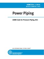
Page 79 Figure 3.19.8.2
Delete Items (a) and (b) and Notes and substitute the following:
Licensed to LUU MINH LUAN on 26 Feb 2002. Single user licence only. Storage, distribution or use on network prohibited.
AMDT
No. 1
APR.
2001
NOTES:
1 Reinforcing saddles are to be used only on 90° branches.
2 When a ring or pad is added as reinforcement (see Figure 3.19.8.2(b)), the value of reinforcing area may
be taken in the same manner in which excess material in the main pipe is considered, provided a full
penetration weld is used between the branch, main pipe, and ring or pad.
3 The ratio of the width to thickness of a ring and a pad shall be as close to 4:1 as the available horizontal
space allows within the limits of the reinforcing zone along the main pipe and the outside diameter of the
branch allows, but the ratio shall be not less than 1:1.
FIGURE 3.19.8.2 (in part)
REINFORCEMENT OF BRANCH CONNECTIONS
AMDT
No. 1
APR.
2001
Pages 80 to 81 Clause 3.19.8.4
1 Delete Equation 3.19.8.4(1) and substitute ‘ A7 = (tmh − G h)d1 (2 − sin α) ’.
2 Delete Equation 3.19.8.4(2) and substitute ‘ A7 = 0.5(tmh − G h)d1 (2 − sin α) ’.
AMDT
No. 1
APR.
2001
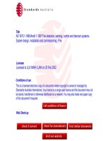
Pages 82 to 84 Clauses 3.19.9.2 to 3.19.9.5 including Figure 3.19.9.2:
Delete Clauses and Figure and substitute the following:
3.19.9.2
Dc
Notation
The notation is as follows (see also Figure 3.19.9.2):
= corroded internal diameter of main pipe, in millimetres
Doh = outside diameter of main pipe, in millimetres
dc
= corroded internal diameter of extruded outlet measured at the level of the
outside surface of the main pipe, in millimetres
H
= height of the reinforcement zone, in millimetres
Licensed to LUU MINH LUAN on 26 Feb 2002. Single user licence only. Storage, distribution or use on network prohibited.
= 0.7(DobTo)1/2
K
= factor determined by the ratio of branch diameter to main pipe diameter
(see Clause 3.19.9.4)
tb
= actual (by measurement), or minimum wall thickness of branch pipe,
permissible in the pipe specification, in millimetres
th
= actual (by measurement), or minimum wall thickness of main pipe,
permissible in the pipe specification, in millimetres
To
= corroded finished thickness of extruded outlet, measured to a point on or
beyond the outside surface of the main pipe, in millimetres
Dob = outside diameter of branch, in millimetres
d1
= corroded inside diameter of branch, in millimetres
ho
= height of the extruded outlet, in millimetres
≥ ro, (except as shown in Figure 3.19.9.2(b))
r1
= half-width of reinforcement zone, in millimetres
= dc
ro
= radius of external contoured portion of outlet measured in the plane
containing the axes of the main pipe and branch (see Clause 3.19.9.3), in
millimetres
tmb
= required wall thickness of branch, in millimetres
tmh
= required wall thickness of main pipe, in millimetres.
3.19.9.3 Radius of external contour The radius of the external contoured portion of an
outlet (see Figure 3.19.9.2) shall comply with the following:
(a)
(b)
Minimum value of ro:
(i)
For outlet outside diameter ≤760 mm . . . . . . . . . . . . 0.05Dob mm.
(ii)
For outlet outside diameter >760 mm . . . . . . . . . . . . 38 mm.
Maximum value of ro:
(i)
For outlet outside diameter <190 mm . . . . . . . . . . . . 32 mm.
(ii)
For outlet outside diameter ≥190 mm . . . . . . . . . . . . (0.10Dob + 13)mm.
AMDT
No. 1
APR.
2001
(c)
More than one radius:
Where the external contour contains more than one radius, the radius of best fit of
any arc sector of 45° shall comply with Item (a) and the radius at any point shall
comply with Item (b).
Machining shall not be employed to achieve compliance with the requirements of
Items (a), (b), and (c).
3.19.9.4 Required reinforcement area The required reinforcement area is defined as
equal to K(tmh − Gh) dc, where K shall be determined as follows:
(a)
For Dob/Doh ≤ 0.15 . . . . . . . . . . . . . . . . . . . . . . K = 0.70.
(b)
For Dob/Doh > 0.15 and ≤ 0.60 . . . . . . . . . . . . . . K = 0.60 + 2/3 × (Dob/Doh).
(c)
For Dob/Doh > 0.60 . . . . . . . . . . . . . . . . . . . . . . K = 1.00.
3.19.9.5
+ A 3,
Reinforcement area
The area required for reinforcement (AR) shall be A1 + A 2
Licensed to LUU MINH LUAN on 26 Feb 2002. Single user licence only. Storage, distribution or use on network prohibited.
where
A1
A2
A3
=
area lying within the reinforcement zone resulting from any excess
wall thickness available in the main pipe
=
dc(th − tmh)
=
area lying within the reinforcement zone resulting from excess wall
thickness available in the branch pipe
=
2H(tb − tmb)
=
area lying within the reinforcement zone resulting from excess
thickness available in the extruded outlet lip
=
2ro(To − tb − Gb)
Licensed to LUU MINH LUAN on 26 Feb 2002. Single user licence only. Storage, distribution or use on network prohibited.
AMDT
No. 1
APR.
2001
NOTES:
1 Taper bore ID (if required) to match branch pipe 1:3 maximum taper.
2 Corrosion and other allowances are shown at bores.
FIGURE 3.19.9.2
REINFORCED EXTRUDED OUTLETS
AMDT
No. 1
APR.
2001
Page 86 Clause 3.23.2.2
Delete Clause and substitute the following:
3.23.2.2 Elevated temperature piping A partial penetration weld to join an attachment
for Class 1 piping is not permitted without detailed analysis for design temperatures
above 250°C.
A partial penetration weld to join an attachment may be permitted, with agreement by
the parties concerned, for Class 2A piping for design temperatures above 250°C.
AMDT
No. 1
APR.
2001
Page 86 Clause 3.23.2.3
AMDT
No. 1
APR.
2001
Page 86 Clause 3.23.4
Second line, delete ‘Class 2’ and substitute ‘Class 2P’.
1
Equation 3.23.4(2), delete equation and substitute:
q =
Licensed to LUU MINH LUAN on 26 Feb 2002. Single user licence only. Storage, distribution or use on network prohibited.
2
R
6 We
±
L
L2
Delete Note and substitute the following:
NOTES:
1 Other methods given in WRC 198 and BS 5500 are also acceptable.
2 Due consideration should be given to the level of stress already in the pipe due to other
loads.
AMDT
No. 1
APR.
2001
Page 92 Table 3.24.3.5
AMDT
No. 1
APR.
2001
Page 107 Clause 3.25.2.1
Row 2, ‘T ≤ 260’, Column 3 ‘Size range’, delete ‘DN36’ and substitute ‘DN32’.
Delete ‘2.25.2.1’ and substitute ‘3.25.2.1’.
AMDT
No. 1
APR.
2001
Page 108 Clause 3.25.5 (new)
Add new Clause as follows:
3.25.5
Piping located below ground level
3.25.5.1 General Piping which is to be located below ground level shall also comply
with this Clause (3.25.5). Such piping includes that installed in basements, cellars,
mines, trenches or directly in the ground in order to provide services below ground, or to
facilitate traffic on roads, or within buildings, or to protect piping from fire, sun or
external interference.
In all cases, appropriate provision shall be made for —
(a)
prevention or collection, drainage and removal of significant leaks from piping,
particularly lethal and very harmful fluids and gases heavier than air which may
seriously deplete oxygen levels in working spaces or form combustible mixtures;
and
(b)
removal of ground water or other material (e.g. silt or debris in open or covered
trenches) which would seriously affect the performance or safety of the piping.
Licensed to LUU MINH LUAN on 26 Feb 2002. Single user licence only. Storage, distribution or use on network prohibited.
3.25.5.2 Buried piping Piping buried directly in the ground should, if practicable, be
avoided particularly where contents are at temperatures above 100°C or below 5°C.
The design shall consider, and when necessary, make provision for —
(a)
the soil and surface loads on the piping, particularly for low thickness/diameter
ratio or vacuum piping;
(b)
suitable support against ground settlement or conditions which could damage the
piping or its protection coating;
(c)
protection against external corrosion by suitable material selection, corrosion
allowance, coatings, clean fill, drainage or cathodic protection (see Clause 7.4).
(d)
protection against stray current corrosion;
(e)
appropriate means for pressure testing, inspection, internal cleaning, isolation,
drainage (slope) and detection of leaks which could cause significant losses or
hazards to personnel, plant or environment;
(f)
possible rotation of piping which will encounter selective bottom erosion; and
(g)
suitable markers and location plans to avoid external damage when modifying or
adding services and to facilitate inspection.
See AS 2885 for further guidance applicable to buried piping.
AMDT
No. 1
APR.
2001
AMDT
No. 1
APR.
2001
Page 129 Clause 6.5.1
1
Delete ‘for all liquids are’ and substitute ‘is’.
2
Item (e), delete ‘2000 kPa’ and substitute ‘2 MPa’.
3
Item (e), delete ‘400 kPa’, and substitute ‘0.4 MPa’.
Page 129 Clause 6.5.2
1
Second line after ‘spot non-destructive examination’ add ‘(other than visual
examination).’
2
Delete ‘Classes 2 and 3’ and substitute ‘Classes 1 and 2’.
AMDT
No. 1
APR.
2001
Pages 130 to 132 Clauses 6.6 to 6.10
Delete Clauses 6.6 to 6.10 and substitute the following:
6.6
PRESSURE TESTS
6.6.1 General
Standard.
Pressure tests shall be conducted in accordance with AS 4037 and this
A pressure test on piping is used to achieve the following:
(a)
Detect leakage at components and joints.
(b)
Assist in assessing the adequacy of the piping system design, materials and
fabrication, e.g. that there is sufficient wall thickness, and material strength.
(c)
Partially relieve residual fabrication stresses and sometimes modify shape.
Licensed to LUU MINH LUAN on 26 Feb 2002. Single user licence only. Storage, distribution or use on network prohibited.
6.6.2 Types of pressure tests Piping shall pass one of the following tests as
appropriate. More tests may be specified by the manufacturer:
(a)
Hydrostatic test (see Clause 6.7).
(b)
Pneumatic test (see Clause 6.8.1).
(c)
Initial service leak test (see Clause 6.9 for method of application and Clauses 6.8.2
and 6.8.3 for circumstances in which they are used).
(d)
Increased non-destructive examination and leak test (see Clause 6.8.3).
(e)
Proof hydrostatic test (see Clause 6.8.4).
Alternatives to a hydrostatic test should be considered where any of the following apply:
(i)
The mass of the water would damage the pipe or its supports.
(ii)
The test fluid would damage linings or internal insulation.
(iii) Residual moisture would contaminate or cause failure of a process or cause
corrosion or other unacceptable hazard.
(iv)
Low metal temperature during the test would cause risk of brittle fracture (see
AS/NZS 3788 and AS 4037 for information on MDMT).
(v)
New piping isolated from existing systems by a valve, in cases where water from
the hydrostatic test, if leaked past the valve, would seriously contaminate the
existing system.
An alternative to pneumatic testing should be considered when it would introduce an
unacceptable hazard from the possible release of stored energy, particularly if low metal
temperature during the test would lead to the risk of brittle fracture.
6.7
HYDROSTATIC TEST
6.7.1 Application A hydrostatic test shall be made on all piping except when other
tests are permitted in lieu by AS 4037 or Clause 6.8.
6.7.2 Test pressure The hydrostatic test pressure shall be calculated in accordance
with Appendix U. The hydrostatic test pressure at any point in the piping system shall
comply with the pressures specified. Additionally, the minimum test pressure required
for any service or material is specified in Paragraph U1.
The test pressure at any point includes any static hydrostatic head due to the test fluid.
NOTE: For guidance on testing pressure vessels and piping together, see Paragraphs U5 and
U7 for testing jacketed piping.
6.7.3 Hold period The test pressure shall be held for the time specified in
Table 6.7.3. The pressure in the piping shall then be dropped to 85–90% of the test
pressure for visual examination.
AMDT
No. 1
APR.
2001
TABLE
6.7.3
HOLD PERIOD FOR HYDROSTATIC TEST
Minimum hold period, minutes
Nominal size
Test pressure, kPa
≤DN 300
>DN 300
6.8
≤700
>700
10
20
15
25
ALTERNATIVE TO HYDROSTATIC TEST
6.8.1 Alternative to hydrostatic test by use of pneumatic testing As an alternative
to hydrostatic testing, and where agreed by the parties concerned, a pneumatic test may
be used. The test shall be conducted in accordance with AS 4037. The test pressure shall
be 90 percent of that specified in Clause 6.7.2.
Licensed to LUU MINH LUAN on 26 Feb 2002. Single user licence only. Storage, distribution or use on network prohibited.
6.8.2 Alterative to hydrostatic test by use of initial service leak test At the owner’s
option, piping is exempt from hydrostatic test when each of the following apply:
(a)
The pipe is certified by the pipe manufacturer to a listed Standard as leak tight by
hydrostatic test or non-destructive examination method.
(b)
The piping is made from material groups A1, A2, A3, A4, B, C, E, K, M or nonferrous.
(c)
The design temperature is less than or equal to 180°C and greater than −30°C.
(d)
The design pressure is less than 2 MPa if the hoop stress ≤0.5f or 1 MPa if the
hoop stress >0.5f.
(e)
The fluid is either —
(i)
fluid types 3 and 4;
(ii)
steam; or
(iii)
caustic soda or sodium cyanide solutions as used in the mining industry.
In lieu of a hydrostatic test, each of the following shall be carried out:
(i)
100% visual examination of all welds (see Table 8.4 and AS 4037 for form and
working omissions).
(ii)
An initial service leak test in accordance with Clause 6.8A.
6.8.3 Alternative to hydrostatic
examination and leak test
test
by
use
of
increased
non-destructive
6.8.3.1 General Increased non-destructive examination and leak tests may be used in
lieu of a hydrostatic test for butt welds, branch welds, flange welds and minor
attachments as given in this Clause 6.8.3. Leak tests should be used on mechanical
joints.
6.8.3.2 Butt welds, branch welds and flange welds For Classes 1 and 2 piping, butt
welds, branch welds, and flange welds, including tie-in and cut-in-welds, may be
exempted from hydrostatic testing where these welds comply with each of the following:
(a)
The pipe is certified by the pipe manufacturer to a listed Standard as leak tight by
hydrostatic test or a non-destructive examination method.
AMDT
No. 1
APR.
2001
(b)
Butt welds are located in straight pipe and are not less than one pipe diameter from
any branch connection or bend. This requirement does not apply to butt weld
fittings covered in Clause 2.2.1(f).
Branch welds are located in straight pipe and are not less than one pipe diameter
from any butt weld or bend.
(c)
They comply with the ovality requirements of this Standard.
(d)
They are subject to 100% visual examination.
(e)
They comply with appropriate non-destructive examination Standards for —
(i)
100% radiographic examination, plus either magnetic particle testing or
penetrant examination; or
(ii)
100% ultrasonic examination, plus either magnetic particle testing or
penetrant examination.
(iii)
Fillet welded pressure welds (e.g. slip-on flange or socket weld fittings)
either 100% magnetic particle testing or 100% penetrant examination in
accordance with AS 4037.
Licensed to LUU MINH LUAN on 26 Feb 2002. Single user licence only. Storage, distribution or use on network prohibited.
NOTE: When Items (i) and (ii) are not practical, refer to Clause 6.5.3.
(f)
Examinations (d) and (e) have been carried out after any postweld heat treatment
has been carried out.
(g)
They comply with the limits of surface imperfection for piping given in AS 4037.
(h)
They pass an initial service leak test (Clause 6.8A) or the sensitive leak test
(AS 4037). For lethal fluids it shall be the sensitive leak test.
For Class 3 piping, butt welds, branch welds and flange welds (including tie-in and cutin welds) are exempt from hydrostatic testing where the welds comply with the initial
service leak test. Any longitudinal welds shall be subject to 20% radiograhic or
ultrasonic examination including either magnetic particle testing or penetrant
examination.
6.8.3.3 Mechanical joints Mechanical joints used within their pressure rating for the
service conditions (e.g. bolting and screwing) may be exempted from hydrostatic testing
provided that the completed piping is subjected to —
(a)
100% visual examination;
(b)
a sensitive leak test (see AS 4037) where the contents are fluid Types 1 or 2;
(c)
an initial service leak test for piping other than Item (b); and
(d)
the components being joined have been hydrostatically tested at the time of
manufacture or its equivalent.
6.8.3.4 Minor attachments The welding or brazing of minor attachments, such as
temperature and pressure tappings (DN 40 and below) and minor structural attachments,
are exempt from hydrostatic provided —
(a)
they are subject to 100% visual examination;
(b)
the joint is subject to 100% magnetic particle or penetrant examination to
AS 4037; and
(c)
failure will not be detrimental to the piping in service.
6.8.4 Proof hydrostatic test Where the strength of components cannot readily be
calculated, the design pressure may be determined in accordance with the proof
hydrostatic test specified in AS 1210.
AMDT
No. 1
APR.
2001
6.8A INITIAL SERVICE LEAK TEST The initial service leak test when used shall
be made during or prior to the initial operation and after taking all necessary precautions.
The leak test shall be made with the service fluid at the operating condition of the piping
by examining for leaks at each joint and connection not previously pressure tested in
accordance with this Standard. Where the pressurized fluid is gas or vapour, a
preliminary leak test shall be made at one-quarter operating pressure but not more than
200 kPa. When the process fluid is Type 2 (very harmful), it is recommended that the
preliminary leak test be carried out using an inert medium. The pressure shall then be
increased gradually in steps until the operating pressure is reached, holding at each step
long enough to equalize piping strain and check for leaks.
Licensed to LUU MINH LUAN on 26 Feb 2002. Single user licence only. Storage, distribution or use on network prohibited.
6.9 TESTING PRESSURE-LIMITING DEVICES, RELIEF VALVES, PRESSURE
REGULATORS, AND CONTROL EQUIPMENT Pressure-limiting devices, relief
valves, pressure regulators, and control equipment shall be examined for the following:
(a)
Good mechanical condition.
(b)
Adequate capacity, effectiveness, and reliability for operation of the intended
service.
(c)
Proper functioning at the correct pressure and temperature.
(d)
Proper installation, and protection from foreign materials or condition that may
prevent proper operation.
(e)
Compliance with the relevant product Standard.
6.10 REPORT After Class 1 or 2 piping has been completed and tested, the
fabricator or manufacturer shall add to the manufacturer’s data report that the piping has
been tested in accordance with this Standard.
AMDT
No. 1
APR.
2001
Page 140 Appendix A
1 Insert new reference ‘4343 Pressure equipment — Hazard levels’.
2 Delete reference AS 4037, substitute ‘AS 4037 Pressure equipment — Examination and
testing’.
AMDT
No. 1
APR.
2001
Page 154 Appendix D
Insert new last paragraph as follows:
Design strengths at intermediate temperatures may be obtained by linear interpolation.
AMDT
No. 1
APR.
2001
Pages 157–160 Table D2
1 Column 7, delete ‘fe (max.)*’ and substitute ‘fc, fh (max.)*’.
2 Footnote, delete ‘fe (max.)’ and substitute ‘f c, fh (max.)’.
3 Yield strength 200 MPa, first row:
Column 14, insert ‘86’.
Column 15, insert ‘79’.
Column 16, insert ‘75’.
AMDT
No. 1
APR.
2001
Page 161 Appendix D
Second paragraph, delete ‘Re 250’ and substitute ‘Re 240’.
AMDT
No. 1
APR.
2001
Page 161 Table D4
AMDT
No. 1
APR.
2001
Pages 162–163
Title, delete ‘Re 250’ and substitute ‘Re 240’.
Table D5
1 Column 7, delete ‘fc (max.)* and substitute ‘fc, fh (max.)*’.
2 Footnote, delete ‘fc (max.)’ and substitute ‘f c, fh (max.)’.
AMDT
No. 1
APR.
2001
Pages 164–168 Table D6
1 Column 10, delete ‘fc (max.)* and substitute ‘fc, fh (max.)*’.
2 Footnote, delete ‘fc (max.)’ and substitute ‘f c, fh (max.)’.
AMDT
No. 1
APR.
2001
Pages 169–170 Table D7
1 Column 10, delete ‘fe (max.)* and substitute ‘fc, fh (max.)*’.
Licensed to LUU MINH LUAN on 26 Feb 2002. Single user licence only. Storage, distribution or use on network prohibited.
2 Footnote, delete ‘fe (max.)’ and substitute ‘f c, fh (max.)’.
AMDT
No. 1
APR.
2001
Pages 171–173 Table D8
1 Column 11, delete ‘fe (max.)* and substitute ‘fc, fh (max.)*’.
2 Footnote, delete ‘fe (max.)’ and substitute ‘f c, fh (max.)’.
AMDT
No. 1
APR.
2001
Pages 174–176 Table D9
1 Column 11, delete ‘fc (max.)* and substitute ‘fc, fh (max.)*’.
2 Footnote, delete ‘fc (max.)’ and substitute ‘f c, fh (max.)’.
AMDT
No. 1
APR.
2001
Page 177 Table D10
1 Column 10, delete ‘fe (max.)* and substitute ‘fc, fh (max.)*’.
2 Footnote, delete ‘fe (max.)’ and substitute ‘f c, fh (max.)’.
AMDT
No. 1
APR.
2001
Page 178 Table D11
1 Column 8, delete ‘fe (max.)* and substitute ‘fc, fh (max.)*’.
2 Footnote, delete ‘fe (max.)’ and substitute ‘f c, fh (max.)*’.
AMDT
No. 1
APR.
2001
Page 184 Table G1
Delete the entries first 5 columns under ‘Material’ for type ‘carbon steels’ and type ‘low
alloy steels 1Cr-0.2Mo’ and substitute the following:
Material
Specification
Grade
CARBON STEELS
AS/NZS 1110
AS B 148
AS 2465
4.6
Class 2
2
All
All
All
AS/NZS 1110
5.8
All
LOW ALLOY
STEELS
1Cr-0.2Mo
Temper
Dia.
or size (mm)
(Note 1)
Type
AS 2465
5
>24
AS/NZS 1110
8.8
All
AS 2465
AS/NZS 1252
5
—
≤24
All
ASTM A 320
L7, L7A,
L7B, L7C
≤63
ASTM A 193
B7
≤63
Licensed to LUU MINH LUAN on 26 Feb 2002. Single user licence only. Storage, distribution or use on network prohibited.
63
AMDT
No. 1
APR.
2001
Page 192 Appendix J
1 Paragraph J2, Equation J2, delete ‘p = rG(B)½ × 10’ and substitute
‘p = rG(B)½ × 10−6’
2 Paragraph J3, first line, after ‘4f ’ insert ‘(where 4f is the Darcy friction factor)’.
AMDT
No. 1
APR.
2001
Page 197 Appendix L
AMDT
No. 1
APR.
2001
Pages 199–200 Appendix L
Paragraph L1, second paragraph after ‘angle’ insert ‘, γ (see Paragraph L2),’.
1 Equation L5(7), delete equation and substitute:
2t a
2t a
ε =
or
d1 t a
D1 − t a
2 Equation L5(11), delete equation and substitute:
Y =
AMDT
No. 1
APR.
2001
p (d1 + t a)
2f1 e1 t a
Page 204 Figure L3
Curve c, delete ‘x
AMDT
No. 1
APR.
2001
− 0.16957’
f
0.90216 1
and substitute, ‘x
p
Page 206 Figure L5
1 Delete ‘Z n’ and substitute ‘Zn’.
2 Delete ‘Bu + Cu2’ and substitute ‘Bu + Cu2’.
− 0.19449’
f
0.90216 1
p
AMDT
No. 1
APR.
2001
Page 264 Appendix U
Delete Appendix U and substitute the following:
APPENDIX U
HYDROSTATIC TEST PRESSURE
(Normative)
U1
GENERAL
U1.1 Scope This Appendix sets out requirements for the determination of hydrostatic
test pressure for various materials and service conditions. It also contains examples of
the calculation of hydrostatic test pressure for various piping types. See Paragraph U8.
Licensed to LUU MINH LUAN on 26 Feb 2002. Single user licence only. Storage, distribution or use on network prohibited.
U1.2 Requirements for hydrostatic test pressure The hydrostatic test pressure for
any service and system shall be the minimum of Items (a), (b) and (c), but shall not
exceed Item (c) as follows:
(a)
Phcalc (see Paragraphs U2, U3, U4 and U6).
(b)
The maximum test pressure for any component or in-line equipment except
pressure vessels. For pressure vessels see Paragraph U5.
(c)
Phmax as calculated from Equation U1.2(1).
Phmax = f h ×
2t
D
. . . U1.2(1)
where
Phmax = maximum pipe hydrostatic test pressure, in megapascals
fh
= 90% specified minimum yield strength at test temperature, in
megapascals
= 0.9 Re
. . . U1.2(2)
D
= measured (or maximum per purchase specification) outside diameter
of pipe, in millimetres
t
= measured (or minimum per purchase specification) wall thickness, in
millimetres
Re
= specified minimum yield strength at test temperature, in megapascals
U2 FERRITIC, AUSTENITIC AND FERRITIC-AUSTENITIC STEEL PIPING,
CLASSES 1, 2A AND 3
U2.1 Steam and water piping associated with steam boilers The calculated
hydrostatic test pressure shall be determined from the following equation:
Phcalc = 1.5 × P
where
Phcalc = calculated hydrostatic test pressure, in megapascals
P
= design pressure, in megapascals
. . . U2.1(1)
AMDT
No. 1
APR.
2001
U2.2 For all other piping services The calculated hydrostatic test pressure shall be
determined from the following equation:
Phcalc = 0.83 ×
Re
f
. . . U2.2(1)
× P
where
Phcalc = calculated hydrostatic test pressure, in megapascals
P
= design pressure, in megapascals
Re
= specified minimum yield strength at test temperature, in megapascals
f
= design strength at design temperature, in megapascals
and
Maximum value of 0.83 ×
Re
f
3.5
. . . U2.2(2)
Licensed to LUU MINH LUAN on 26 Feb 2002. Single user licence only. Storage, distribution or use on network prohibited.
NOTE: Equation U2.1(1) is based on BS 806. Some values of R e and f are listed in
Appendix D.
U3 FERRITIC STEEL PIPING CLASS 2P
for piping to Class 2P is Phcalc = 1.25 × P
The calculated hydrostatic test pressure
. . . U3(1)
where
Phcalc
=
calculated hydrostatic test pressure, in megapascals
P
=
design pressure, in megapascals
U4 NON-FERROUS METALS
The calculated hydrostatic test pressure shall be
determined from the following equation:
Phcalc
except that
ft
1.5P
ft
f
f
. . . U4(1)
shall not exceed 6.5,
where
ft
=
design strength at test temperature, in megapascals
f
=
design strength at design temperature, in megapascals
U5 PIPING AND PRESSURE VESSELS TESTED TOGETHER For piping
attached to a pressure vessel where the test pressure is not more than the test pressure for
the vessel, the piping may be tested with the vessel at the test pressure of the piping.
Where the test pressure of the piping is greater than the vessel test pressure and it is not
practicable to isolate the piping from the vessel, the piping and the vessel may be tested
together at the test pressure of the vessel provided that —
(a)
the owner agrees; and
(b)
the test pressure of the vessel is not less than 77% of the piping calculated test
pressure adjusted for temperature (see Paragraphs U2, U3 and U4).
U6 PIPING SUBJECT TO EXTERNAL PRESSURE Piping subject to external
pressure in service shall be tested to an internal hydrostatic test pressure of the maximum
of Items (a) and (b) but shall not be less than Item (b) as follows:
(a)
Phcalc = 1.5 Pdiff
. . . U6(1)
AMDT
No. 1
APR.
2001
where
Pdiff = differential design pressure, in megapascals
(b)
100 kPa.
U7 JACKETED PIPING The test pressure for internal piping of jacketed piping
shall be determined according to the internal or external design pressure, whichever is
critical using Paragraph U1. The test shall, if necessary, be performed before completion
of the jacket so that any joints of the internal piping can be visually inspected.
The test pressure for the jacket shall be determined in accordance with Paragraph U1 and
according to the design pressure of the jacket, unless otherwise limited in the
engineering design.
U8
EXAMPLES
Example 1:
Paragraph U2
Service
= other than steam or water
Licensed to LUU MINH LUAN on 26 Feb 2002. Single user licence only. Storage, distribution or use on network prohibited.
Pipe specification = API 5L B
Class
= 1 or 2A
Temperature
= 50°C
Design life
= indefinite
Size
= 273 × 4.8
Max. OD
= 273 mm
Min. thickness
= 4.8 mm
Re
= 241 MPa (from Table D4 or material specification)
Rm
= 413 MPa (from Table D4 or material specification)
f
Re
= 160 MPa depends on
1.5
P
= 5.62 MPa
Phmax
= fh ×
2t
D
= 7.63 MPa
= 0.83
Phcalc
Re
f
× P
= 1.25 P
NOTE: 0.83 ×
Re
= 7.03 MPa
(whenever f
=
Re
1.5
, P h = 1.25 P )
Since Phcalc < Phmax hydrostatic test pressure is 7.03 MPa.
For steam or water service:
Phcalc
= 1.5 P
= 8.43 MPa
Since Phcalc > Phmax hydrostatic test pressure is 7.63 MPa.
f
< 3.5