Automatic control for commerical buildings HVAC
Bạn đang xem bản rút gọn của tài liệu. Xem và tải ngay bản đầy đủ của tài liệu tại đây (4.23 MB, 512 trang )
ENGINEERING MANUAL of
AUTOMATIC
CONTROL for
COMMERCIAL BUILDINGS
SI Edition
Copyright 1989, 1995, and 1997 by Honeywell Inc.
All rights reserved. This manual or portions thereof may not be reporduced
in any form without permission of Honeywell Inc.
Library of Congress Catalog Card Number: 97-77856
Home and Building Control
Honeywell Inc.
Honeywell Plaza
P.O. Box 524
Minneapolis MN 55408-0524
Home and Building Control
Honeywell Limited-Honeywell Limitée
155 Gordon Baker Road
North York, Ontario
M2H 3N7
Honeywell Latin American Region
480 Sawgrass Corporate Parkway
Suite 200
Sunrise FL 33325
Honeywell Europe S.A.
3 Avenue du Bourget
1140 Brussels
Belgium
Honeywell Asia Pacific Inc.
Room 3213-3225
Sun Hung Kai Centre
No. 30 Harbour Road
Wanchai
Hong Kong
Printed in USA
ii
ENGINEERING MANUAL OF AUTOMATIC CONTROL
FOREWORD
The Minneapolis Honeywell Regulator Company published the first edition of the Engineering Manual of
Automatic Control in l934. The manual quickly became the standard textbook for the commercial building
controls industry. Subsequent editions have enjoyed even greater success in colleges, universities, and contractor
and consulting engineering offices throughout the world.
Since the original 1934 edition, the building control industry has experienced dramatic change and made
tremendous advances in equipment, system design, and application. In this edition, microprocessor controls are
shown in most of the control applications rather than pneumatic, electric, or electronic to reflect the trends in
industry today. Consideration of configuration, functionality, and integration plays a significant role in the
design of building control systems.
Through the years Honeywell has been dedicated to assisting consulting engineers and architects in the
application of automatic controls to heating, ventilating, and air conditioning systems. This manual is an outgrowth
of that dedication. Our end user customers, the building owners and operators, will ultimately benefit from the
efficiently designed systems resulting from the contents of this manual.
All of this manual’s original sections have been updated and enhanced to include the latest developments in
control technology and use the International System of Units (SI). A new section has been added on indoor air
quality and information on district heating has been added to the Chiller, Boiler, and Distribution System
Control Applications Section.
This third SI edition of the Engineering Manual of Automatic Control is our contribution to ensure that we
continue to satisfy our customer’s requirements. The contributions and encouragement received from previous
users are gratefully acknowledged. Further suggestions will be most welcome.
Minneapolis, Minnesota
December, 1997
KEVIN GILLIGAN
President, H&BC Solutions and Services
ENGINEERING MANUAL OF AUTOMATIC CONTROL
iii
iv
ENGINEERING MANUAL OF AUTOMATIC CONTROL
PREFACE
The purpose of this manual is to provide the reader with a fundamental understanding of controls and how
they are applied to the many parts of heating, ventilating, and air conditioning systems in commercial buildings.
Many aspects of control are presented including air handling units, terminal units, chillers, boilers, building
airflow, water and steam distribution systems, smoke management, and indoor air quality. Control fundamentals,
theory, and types of controls provide background for application of controls to heating, ventilating, and air
conditioning systems. Discussions of pneumatic, electric, electronic, and digital controls illustrate that applications
may use one or more of several different control methods. Engineering data such as equipment sizing, use of
psychrometric charts, and conversion formulas supplement and support the control information. To enhance
understanding, definitions of terms are provided within individual sections.
Building management systems have evolved into a major consideration for the control engineer when evaluating
a total heating, ventilating, and air conditioning system design. In response to this consideration, the basics of
building management systems configuration are presented.
The control recommendations in this manual are general in nature and are not the basis for any specific job or
installation. Control systems are furnished according to the plans and specifications prepared by the control
engineer. In many instances there is more than one control solution. Professional expertise and judgment are
required for the design of a control system. This manual is not a substitute for such expertise and judgment.
Always consult a licensed engineer for advice on designing control systems.
It is hoped that the scope of information in this manual will provide the readers with the tools to expand their
knowledge base and help develop sound approaches to automatic control.
ENGINEERING MANUAL OF AUTOMATIC CONTROL
v
vi
ENGINEERING MANUAL OF AUTOMATIC CONTROL
ENGINEERING MANUAL of
AUTOMATIC
CONTROL
CONTENTS
Foreward
............................................................................................................
iii
Preface
............................................................................................................
v
Control System Fundamentals ..........................................................................................
1
Control Fundamentals
............................................................................................................
Introduction ..........................................................................................
Definitions ............................................................................................
HVAC System Characteristics .............................................................
Control System Characteristics ...........................................................
Control System Components ..............................................................
Characteristics and Attributes of Control Methods ..............................
3
5
5
8
15
30
35
Psychrometric Chart Fundamentals
............................................................................................................
Introduction ..........................................................................................
Definitions ............................................................................................
Description of the Psychrometric Chart ...............................................
The Abridged Psychrometric Chart .....................................................
Examples of Air Mixing Process ..........................................................
Air Conditioning Processes .................................................................
Humidifying Process ............................................................................
Process Summary ...............................................................................
ASHRAE Psychrometric Charts ..........................................................
37
38
38
39
40
42
43
44
53
53
Pneumatic Control Fundamentals
............................................................................................................
Introduction ..........................................................................................
Definitions ............................................................................................
Abbreviations .......................................................................................
Symbols ...............................................................................................
Basic Pneumatic Control System ........................................................
Air Supply Equipment ..........................................................................
Thermostats ........................................................................................
Controllers ...........................................................................................
Sensor-Controller Systems .................................................................
Actuators and Final Control Elements .................................................
Relays and Switches ...........................................................................
Pneumatic Control Combinations ........................................................
Pneumatic Centralization ....................................................................
Pneumatic Control System Example ...................................................
57
59
59
60
61
61
65
69
70
72
74
77
84
89
90
Electric Control Fundamentals
............................................................................................................
Introduction ..........................................................................................
Definitions ............................................................................................
How Electric Control Circuits are Classified ........................................
Series 40 Control Circuits ....................................................................
Series 80 Control Circuits ....................................................................
Series 60 Two-Position Control Circuits ...............................................
Series 60 Floating Control Circuits ......................................................
Series 90 Control Circuits ....................................................................
Motor Control Circuits ..........................................................................
95
97
97
99
100
102
103
106
107
114
ENGINEERING MANUAL OF AUTOMATIC CONTROL
vii
Electronic Control Fundamentals
............................................................................................................
Introduction ..........................................................................................
Definitions ............................................................................................
Typical System ....................................................................................
Components ........................................................................................
Electronic Controller Fundamentals ....................................................
Typical System Application ..................................................................
119
120
120
122
122
129
130
Microprocessor-Based/DDC Fundamentals ....................................................................................................
Introduction ..........................................................................................
Definitions ............................................................................................
Background .........................................................................................
Advantages .........................................................................................
Controller Configuration ......................................................................
Types of Controllers .............................................................................
Controller Software ..............................................................................
Controller Programming ......................................................................
Typical Applications .............................................................................
131
133
133
134
134
135
136
137
142
145
Indoor Air Quality Fundamentals
............................................................................................................
Introduction ..........................................................................................
Definitions ............................................................................................
Abbreviations .......................................................................................
Indoor Air Quality Concerns ................................................................
Indoor Air Quality Control Applications ................................................
Bibliography .........................................................................................
149
151
151
153
154
164
170
Smoke Management Fundamentals
............................................................................................................
Introduction ..........................................................................................
Definitions ............................................................................................
Objectives ............................................................................................
Design Considerations ........................................................................
Design Priniples ..................................................................................
Control Applications ............................................................................
Acceptance Testing .............................................................................
Leakage Rated Dampers ....................................................................
Bibliography .........................................................................................
171
172
172
173
173
175
178
181
181
182
Building Management System Fundamentals .................................................................................................
Introduction ..........................................................................................
Definitions ............................................................................................
Background .........................................................................................
System Configurations ........................................................................
System Functions ................................................................................
Integration of Other Systems ...............................................................
183
184
184
185
186
189
196
viii
ENGINEERING MANUAL OF AUTOMATIC CONTROL
Control System Applications
.......................................................................................... 199
Air Handling System Control Applications ......................................................................................................
Introduction ..........................................................................................
Abbreviations .......................................................................................
Requirements for Effective Control ......................................................
Applications-General ...........................................................................
Valve and Damper Selection ...............................................................
Symbols ...............................................................................................
Ventilation Control Processes .............................................................
Fixed Quantity of Outdoor Air Control .................................................
Heating Control Processes ..................................................................
Preheat Control Processes .................................................................
Humidification Control Process ...........................................................
Cooling Control Processes ..................................................................
Dehumidification Control Processes ...................................................
Heating System Control Process ........................................................
Year-Round System Control Processes ..............................................
ASHRAE Psychrometric Charts ..........................................................
201
203
203
204
206
207
208
209
211
223
228
235
236
243
246
248
261
Building Airflow System Control Applications ...............................................................................................
Introduction ..........................................................................................
Definitions ............................................................................................
Airflow Control Fundamentals .............................................................
Airflow Control Applications .................................................................
References ..........................................................................................
263
265
265
266
280
290
Chiller, Boiler, and Distribution System Control Applications .......................................................................
Introduction ..........................................................................................
Abbreviations .......................................................................................
Definitions ............................................................................................
Symbols ...............................................................................................
Chiller System Control .........................................................................
Boiler System Control ..........................................................................
Hot and Chilled Water Distribution Systems Control ...........................
High Temperature Water Heating System Control ...............................
District Heating Applications................................................................
291
295
295
295
296
297
327
335
374
380
Individual Room Control Applications ............................................................................................................
Introduction ..........................................................................................
Unitary Equipment Control ..................................................................
Hot Water Plant Considerations ..........................................................
395
397
408
424
ENGINEERING MANUAL OF AUTOMATIC CONTROL
ix
Engineering Information
.......................................................................................... 425
Valve Selection and Sizing
............................................................................................................
Introduction ..........................................................................................
Definitions ............................................................................................
Valve Selection ....................................................................................
Valve Sizing .........................................................................................
427
428
428
432
437
Damper Selection and Sizing
............................................................................................................
Introduction ..........................................................................................
Definitions ............................................................................................
Damper Selection ................................................................................
Damper Sizing .....................................................................................
Damper Pressure Drop .......................................................................
Damper Applications ...........................................................................
445
447
447
448
457
462
463
General Engineering Data
............................................................................................................
Introduction ..........................................................................................
Conversion Formulas and Tables ........................................................
Electrical Data .....................................................................................
Properties of Saturated Steam Data ...................................................
Airflow Data .........................................................................................
Moisture Content of Air Data ...............................................................
465
466
466
473
476
477
479
Index
.......................................................................................... 483
x
ENGINEERING MANUAL OF AUTOMATIC CONTROL
SMOKE MANAGEMENT FUNDAMENTALS
CONTROL
SYSTEM
FUNDAMENTALS
ENGINEERING MANUAL OF AUTOMATIC CONTROL
1
SMOKE MANAGEMENT FUNDAMENTALS
SMOKE MANAGEMENT FUNDAMENTALS
2
ENGINEERING MANUAL OF AUTOMATIC CONTROL
CONTROL FUNDAMENTALS
Control Fundamentals
ENGINEERING MANUAL OF AUTOMATIC CONTROL
CONTENTS
Introduction
............................................................................................................
5
Definitions
............................................................................................................
5
HVAC System Characteristics
............................................................................................................
General ................................................................................................
Heating ................................................................................................
General ...........................................................................................
Heating Equipment .........................................................................
Cooling ................................................................................................
General ...........................................................................................
Cooling Equipment ..........................................................................
Dehumidification ..................................................................................
Humidification ......................................................................................
Ventilation ............................................................................................
Filtration ...............................................................................................
8
8
9
9
10
11
11
12
12
13
13
14
Control System Characteristics
............................................................................................................
Controlled Variables ............................................................................
Control Loop ........................................................................................
Control Methods ..................................................................................
General ...........................................................................................
Analog and Digital Control ..............................................................
Control Modes .....................................................................................
Two-Position Control .......................................................................
General .......................................................................................
Basic Two-Position Control .........................................................
Timed Two-Position Control ........................................................
Step Control ....................................................................................
Floating Control ...............................................................................
Proportional Control ........................................................................
General .......................................................................................
Compensation Control ................................................................
Proportional-Integral (PI) Control ....................................................
Proportional-Integral-Derivative (PID) Control ................................
Enhanced Proportional-Integral-Derivative (EPID) Control .............
Adaptive Control ..............................................................................
Process Characteristics .......................................................................
Load ................................................................................................
Lag ..................................................................................................
General .......................................................................................
Measurement Lag .......................................................................
Capacitance ................................................................................
Resistance ..................................................................................
Dead Time ..................................................................................
Control Application Guidelines ............................................................
15
15
15
16
16
16
17
17
17
17
18
19
20
21
21
22
23
25
25
26
26
26
27
27
27
28
29
29
29
ENGINEERING MANUAL OF AUTOMATIC CONTROL
3
CONTROL FUNDAMENTALS
Control System Components
............................................................................................................
Sensing Elements ...............................................................................
Temperature Sensing Elements ......................................................
Pressure Sensing Elements ............................................................
Moisture Sensing Elements ............................................................
Flow Sensors ..................................................................................
Proof-of-Operation Sensors ............................................................
Transducers .........................................................................................
Controllers ...........................................................................................
Actuators .............................................................................................
Auxiliary Equipment .............................................................................
Characteristics and Attributes of Control Methods
..............................................................................
4
30
30
30
31
32
32
33
33
33
33
34
35
ENGINEERING MANUAL OF AUTOMATIC CONTROL
CONTROL FUNDAMENTALS
INTRODUCTION
Automatic controls can optimize HVAC system operation.
They can adjust temperatures and pressures automatically to
reduce demand when spaces are unoccupied and regulate
heating and cooling to provide comfort conditions while limiting
energy usage. Limit controls ensure safe operation of HVAC
system equipment and prevent injury to personnel and damage
to the system. Examples of limit controls are low-limit
temperature controllers which help prevent water coils or heat
exchangers from freezing and flow sensors for safe operation
of some equipment (e.g., chillers). In the event of a fire,
controlled air distribution can provide smoke-free evacuation
passages, and smoke detection in ducts can close dampers to
prevent the spread of smoke and toxic gases.
This section describes heating, ventilating, and air
conditioning (HVAC) systems and discusses characteristics and
components of automatic control systems. Cross-references are
made to sections that provide more detailed information.
A correctly designed HVAC control system can provide a
comfortable environment for occupants, optimize energy cost
and consumption, improve employee productivity, facilitate
efficient manufacturing, control smoke in the event of a fire,
and support the operation of computer and telecommunications
equipment. Controls are essential to the proper operation of
the system and should be considered as early in the design
process as possible.
HVAC control systems can also be integrated with security
access control systems, fire alarm systems, lighting control
systems, and building and facility management systems to
further optimize building comfort, safety, and efficiency.
Properly applied automatic controls ensure that a correctly
designed HVAC system will maintain a comfortable
environment and perform economically under a wide range of
operating conditions. Automatic controls regulate HVAC system
output in response to varying indoor and outdoor conditions to
maintain general comfort conditions in office areas and provide
narrow temperature and humidity limits where required in
production areas for product quality.
DEFINITIONS
Controlled medium: The medium in which the controlled
variable exists. In a space temperature control system,
the controlled variable is the space temperature and
the controlled medium is the air within the space.
The following terms are used in this manual. Figure 1 at the
end of this list illustrates a typical control loop with the
components identified using terms from this list.
Analog: Continuously variable (e.g., a faucet controlling water
from off to full flow).
Controlled Variable: The quantity or condition that is measured
and controlled.
Automatic control system: A system that reacts to a change or
imbalance in the variable it controls by adjusting other
variables to restore the system to the desired balance.
Controller: A device that senses changes in the controlled
variable (or receives input from a remote sensor) and
derives the proper correction output.
Algorithm: A calculation method that produces a control output
by operating on an error signal or a time series of error
signals.
Corrective action: Control action that results in a change of
the manipulated variable. Initiated when the controlled
variable deviates from setpoint.
Compensation control: A process of automatically adjusting
the setpoint of a given controller to compensate for
changes in a second measured variable (e.g., outdoor
air temperature). For example, the hot deck setpoint
is normally reset upward as the outdoor air temperature
decreases. Also called “reset control”.
Cycle: One complete execution of a repeatable process. In basic
heating operation, a cycle comprises one on period
and one off period in a two-position control system.
Cycling: A periodic change in the controlled variable from one
value to another. Out-of-control analog cycling is
called “hunting”. Too frequent on-off cycling is called
“short cycling”. Short cycling can harm electric
motors, fans, and compressors.
Control agent: The medium in which the manipulated variable
exists. In a steam heating system, the control agent is
the steam and the manipulated variable is the flow of
the steam.
Cycling rate: The number of cycles completed per time unit,
typically cycles per hour for a heating or cooling system.
The inverse of the length of the period of the cycle.
Control point: The actual value of the controlled variable
(setpoint plus or minus offset).
ENGINEERING MANUAL OF AUTOMATIC CONTROL
5
CONTROL FUNDAMENTALS
Deadband: A range of the controlled variable in which no
corrective action is taken by the controlled system and
no energy is used. See also “zero energy band”.
Load: In a heating or cooling system, the heat transfer that the
system will be called upon to provide. Also, the work
that the system must perform.
Deviation: The difference between the setpoint and the value
of the controlled variable at any moment. Also called
“offset”.
Manipulated variable: The quantity or condition regulated
by the automatic control system to cause the desired
change in the controlled variable.
DDC: Direct Digital Control. See also Digital and Digital
control.
Measured variable: A variable that is measured and may be
controlled (e.g., discharge air is measured and
controlled, outdoor air is only measured).
Digital: A series of on and off pulses arranged to convey
information. Morse code is an early example.
Processors (computers) operate using digital language.
Microprocessor-based control: A control circuit that operates
on low voltage and uses a microprocessor to perform
logic and control functions, such as operating a relay
or providing an output signal to position an actuator.
Electronic devices are primarily used as sensors. The
controller often furnishes flexible DDC and energy
management control routines.
Digital control: A control loop in which a microprocessorbased controller directly controls equipment based on
sensor inputs and setpoint parameters. The
programmed control sequence determines the output
to the equipment.
Modulating: An action that adjusts by minute increments and
decrements.
Droop: A sustained deviation between the control point and
the setpoint in a two-position control system caused
by a change in the heating or cooling load.
Offset: A sustained deviation between the control point and
the setpoint of a proportional control system under
stable operating conditions.
Enhanced proportional-integral-derivative (EPID) control:
A control algorithm that enhances the standard PID
algorithm by allowing the designer to enter a startup
output value and error ramp duration in addition to
the gains and setpoints. These additional parameters
are configured so that at startup the PID output varies
smoothly to the control point with negligible overshoot
or undershoot.
On/off control: A simple two-position control system in which
the device being controlled is either full on or full off
with no intermediate operating positions available.
Also called “two-position control”.
Pneumatic control: A control circuit that operates on air
pressure and uses a mechanical means, such as a
temperature-sensitive bimetal or bellows, to perform
control functions, such as actuating a nozzle and
flapper or a switching relay. The controller output
usually operates or positions a pneumatic actuator,
although relays and switches are often in the circuit.
Electric control: A control circuit that operates on line or low
voltage and uses a mechanical means, such as a
temperature-sensitive bimetal or bellows, to perform
control functions, such as actuating a switch or
positioning a potentiometer. The controller signal usually
operates or positions an electric actuator or may switch
an electrical load directly or through a relay.
Process: A general term that describes a change in a measurable
variable (e.g., the mixing of return and outdoor air
streams in a mixed-air control loop and heat transfer
between cold water and hot air in a cooling coil).
Usually considered separately from the sensing
element, control element, and controller.
Electronic control: A control circuit that operates on low
voltage and uses solid-state components to amplify
input signals and perform control functions, such as
operating a relay or providing an output signal to
position an actuator. The controller usually furnishes
fixed control routines based on the logic of the solidstate components.
Proportional band: In a proportional controller, the control
point range through which the controlled variable must
pass to move the final control element through its full
operationg range. Expressed in percent of primary
sensor span. Commonly used equivalents are
“throttling range” and “modulating range”, usually
expressed in a quantity of Engineering units (degrees
of temperature).
Final control element: A device such as a valve or damper
that acts to change the value of the manipulated
variable. Positioned by an actuator.
Hunting: See Cycling.
Proportional control: A control algorithm or method in which
the final control element moves to a position
proportional to the deviation of the value of the
controlled variable from the setpoint.
Lag: A delay in the effect of a changed condition at one point in
the system, or some other condition to which it is related.
Also, the delay in response of the sensing element of a
control due to the time required for the sensing element
to sense a change in the sensed variable.
6
ENGINEERING MANUAL OF AUTOMATIC CONTROL
CONTROL FUNDAMENTALS
may be actuator driven, electronic, or directly activated
by the sensed medium (e.g., pressure, temperature).
Proportional-Integral (PI) control: A control algorithm that
combines the proportional (proportional response) and
integral (reset response) control algorithms. Reset
response tends to correct the offset resulting from
proportional control. Also called “proportional-plusreset” or “two-mode” control.
Throttling range: In a proportional controller, the control point
range through which the controlled variable must pass
to move the final control element through its full
operating range. Expressed in values of the controlled
variable (e.g., Kelvins or degrees Celsius, percent
relative humidity, kilopascals). Also called
“proportional band”. In a proportional room
thermostat, the temperature change required to drive
the manipulated variable from full off to full on.
Proportional-Integral-Derivative (PID) control: A control
algorithm that enhances the PI control algorithm by
adding a component that is proportional to the rate of
change (derivative) of the deviation of the controlled
variable. Compensates for system dynamics and
allows faster control response. Also called “threemode” or “rate-reset” control.
Time constant: The time required for a dynamic component,
such as a sensor, or a control system to reach 63.2
percent of the total response to an instantaneous (or
“step”) change to its input. Typically used to judge
the responsiveness of the component or system.
Reset Control: See Compensation Control.
Sensing element: A device or component that measures the
value of a variable.
Two-position control: See on/off control.
Setpoint: The value at which the controller is set (e.g., the
desired room temperature set on a thermostat). The
desired control point.
Short cycling: See Cycling.
Zero energy band: An energy conservation technique that
allows temperatures to float between selected settings,
thereby preventing the consumption of heating or
cooling energy while the temperature is in this range.
Step control: Control method in which a multiple-switch
assembly sequentially switches equipment (e.g.,
electric heat, multiple chillers) as the controller input
varies through the proportional band. Step controllers
Zoning: The practice of dividing a building into sections for
heating and cooling control so that one controller is
sufficient to determine the heating and cooling
requirements for the section.
MEASURED
VARIABLE
ALGORITHM IN
CONTROLLER
RESET SCHEDULE
OUTDOOR
AIR
15
55
SETPOINT
-2
70
-15
OUTDOOR
AIR
90
OA
TEMPERATURE
MEASURED
VARIABLE
INPUT
OUTPUT
PERCENT
OPEN
CONTROL
POINT
CONTROLLED
VARIABLE
41
VALVE
HOT WATER
SUPPLY
TEMPERATURE
CONTROLLED
MEDIUM
SETPOINT
HW
SETPOINT
71
FINAL CONTROL
ELEMENT
STEAM
CONTROL
AGENT
FLOW
HOT WATER
SUPPLY
MANIPULATED
VARIABLE
64
HOT WATER
RETURN
AUTO
M15127
Fig. 1. Typical Control Loop.
ENGINEERING MANUAL OF AUTOMATIC CONTROL
7
CONTROL FUNDAMENTALS
HVAC SYSTEM CHARACTERISTICS
Figure 2 shows how an HVAC system may be distributed in
a small commercial building. The system control panel, boilers,
motors, pumps, and chillers are often located on the lower level.
The cooling tower is typically located on the roof. Throughout
the building are ductwork, fans, dampers, coils, air filters,
heating units, and variable air volume (VAV) units and diffusers.
Larger buildings often have separate systems for groups of floors
or areas of the building.
GENERAL
An HVAC system is designed according to capacity
requirements, an acceptable combination of first cost and operating
costs, system reliability, and available equipment space.
DUCTWORK
COOLING
TOWER
DAMPER
AIR
FILTER
COOLING
COIL
HEATING
UNIT
VAV BOX
DIFFUSER
FAN
CHILLER
BOILER
PUMP
CONTROL
PANEL
M10506
Fig. 2. Typical HVAC System in a Small Building.
The control system for a commercial building comprises
many control loops and can be divided into central system and
local- or zone-control loops. For maximum comfort and
efficiency, all control loops should be tied together to share
information and system commands using a building
management system. Refer to the Building Management System
Fundamentals section of this manual.
The basic control loops in a central air handling system can
be classified as shown in Table 1.
Depending on the system, other controls may be required
for optimum performance. Local or zone controls depend on
the type of terminal units used.
8
ENGINEERING MANUAL OF AUTOMATIC CONTROL
CONTROL FUNDAMENTALS
Table 1. Functions of Central HVAC Control Loops.
Control
Loop
Classification
Ventilation
Cooling
Description
Basic
Coordinates operation of the outdoor, return, and exhaust air dampers to maintain
the proper amount of ventilation air. Low-temperature protection is often required.
Better
Measures and controls the volume of outdoor air to provide the proper mix of
outdoor and return air under varying indoor conditions (essential in variable air
volume systems). Low-temperature protection may be required.
Chiller control
Maintains chiller discharge water at preset temperature or resets temperature
according to demand.
Cooling tower
control
Controls cooling tower fans to provide the coolest water practical under existing
wet bulb temperature conditions.
Water coil control
Adjusts chilled water flow to maintain temperature.
Direct expansion
Cycles compressor or DX coil solenoid valves to maintain temperature. If
(DX) system control compressor is unloading type, cylinders are unloaded as required to maintain
temperature.
Fan
Heating
Basic
Turns on supply and return fans during occupied periods and cycles them as
required during unoccupied periods.
Better
Adjusts fan volumes to maintain proper duct and space pressures. Reduces system
operating cost and improves performance (essential for variable air volume systems).
Coil control
Adjusts water or steam flow or electric heat to maintain temperature.
Boiler control
Operates burner to maintain proper discharge steam pressure or water temperature.
For maximum efficiency in a hot water system, water temperature should be reset as
a function of demand or outdoor temperature.
HEATING
GENERAL
Building heat loss occurs mainly through transmission,
infiltration/exfiltration, and ventilation (Fig. 3).
TRANSMISSION
VENTILATION
ROOF
Transmission is the process by which energy enters or leaves
a space through exterior surfaces. The rate of energy
transmission is calculated by subtracting the outdoor
temperature from the indoor temperature and multiplying the
result by the heat transfer coefficient of the surface materials.
The rate of transmission varies with the thickness and
construction of the exterior surfaces but is calculated the same
way for all exterior surfaces:
-7°C
PREVAILING
WINDS
DUCT
20°C
EXFILTRATION
DOOR
WINDOW
Energy Transmission per
Unit Area and Unit Time = (TIN - TOUT) x HTC
INFILTRATION
C3971
Where:
TIN = indoor temperature
TOUT = outdoor temperature
HTC = heat transfer coefficient
Fig. 3. Heat Loss from a Building.
The heating capacity required for a building depends on the
design temperature, the quantity of outdoor air used, and the
physical activity of the occupants. Prevailing winds affect the
rate of heat loss and the degree of infiltration. The heating
system must be sized to heat the building at the coldest outdoor
temperature the building is likely to experience (outdoor design
temperature).
ENGINEERING MANUAL OF AUTOMATIC CONTROL
HTC
9
=
joule
Unit Time x Unit Area x Unit Temperature
CONTROL FUNDAMENTALS
Infiltration is the process by which outdoor air enters a
building through walls, cracks around doors and windows, and
open doors due to the difference between indoor and outdoor
air pressures. The pressure differential is the result of
temperature difference and air intake or exhaust caused by fan
operation. Heat loss due to infiltration is a function of
temperature difference and volume of air moved. Exfiltration
is the process by which air leaves a building (e.g., through walls
and cracks around doors and windows) and carries heat with it.
Infiltration and exfiltration can occur at the same time.
STEAM OR
HOT WATER
SUPPLY
FAN
COIL
CONDENSATE
OR HOT WATER
RETURN
UNIT HEATER
STEAM TRAP
(IF STEAM SUPPLY)
C2703
Fig. 5. Typical Unit Heater.
Ventilation brings in fresh outdoor air that may require
heating. As with heat loss from infiltration and exfiltration, heat
loss from ventilation is a function of the temperature difference
and the volume of air brought into the building or exhausted.
HOT WATER
SUPPLY
HEATING EQUIPMENT
HOT WATER
RETURN
Selecting the proper heating equipment depends on many
factors, including cost and availability of fuels, building size
and use, climate, and initial and operating cost trade-offs.
Primary sources of heat include gas, oil, wood, coal, electrical,
and solar energy. Sometimes a combination of sources is most
economical. Boilers are typically fueled by gas and may have
the option of switching to oil during periods of high demand.
Solar heat can be used as an alternate or supplementary source
with any type of fuel.
GRID PANEL
HOT WATER
SUPPLY
HOT WATER
RETURN
SERPENTINE PANEL
C2704
Fig. 6. Panel Heaters.
Figure 4 shows an air handling system with a hot water coil.
A similar control scheme would apply to a steam coil. If steam
or hot water is chosen to distribute the heat energy, highefficiency boilers may be used to reduce life-cycle cost. Water
generally is used more often than steam to transmit heat energy
from the boiler to the coils or terminal units, because water
requires fewer safety measures and is typically more efficient,
especially in mild climates.
Unit ventilators (Fig. 7) are used in classrooms and may
include both a heating and a cooling coil. Convection heaters
(Fig. 8) are used for perimeter heating and in entries and
corridors. Infrared heaters (Fig. 9) are typically used for spot
heating in large areas (e.g., aircraft hangers, stadiums).
DISCHARGE
AIR
WALL
THERMOSTAT
VALVE
HOT WATER
SUPPLY
FAN
HEATING
COIL
DISCHARGE
AIR
FAN
HOT WATER
RETURN
COOLING
COIL
C2702
DRAIN PAN
Fig. 4. System Using Heating Coil.
An air handling system provides heat by moving an air stream
across a coil containing a heating medium, across an electric
heating coil, or through a furnace. Unit heaters (Fig. 5) are
typically used in shops, storage areas, stairwells, and docks.
Panel heaters (Fig. 6) are typically used for heating floors and
are usually installed in a slab or floor structure, but may be
installed in a wall or ceiling.
MIXING
DAMPERS
RETURN
AIR
OUTDOOR
AIR
C3035
Fig. 7. Unit Ventilator.
10
ENGINEERING MANUAL OF AUTOMATIC CONTROL
CONTROL FUNDAMENTALS
application, the refrigerant vaporizes at the lower end in the
warm exhaust air, and the vapor rises toward the higher end in
the cool outdoor air, where it gives up the heat of vaporization
and condenses. A wick carries the liquid refrigerant back to the
warm end, where the cycle repeats. A heat pipe requires no
energy input. For cooling, the process is reversed by tilting the
pipe the other way.
FINNED TUBE
WARM AIR
RETURN AIR
TO OTHER
HEATING UNITS
FLOOR
SUPPLY
RETURN
Controls may be pneumatic, electric, electronic, digital, or a
combination. Satisfactory control can be achieved using
independent control loops on each system. Maximum operating
efficiency and comfort levels can be achieved with a control
system which adjusts the central system operation to the
demands of the zones. Such a system can save enough in
operating costs to pay for itself in a short time.
FROM OTHER
HEATING UNITS
C2705
Fig. 8. Convection Heater.
REFLECTOR
INFRARED
SOURCE
Controls for the air handling system and zones are specifically
designed for a building by the architect, engineer, or team who
designs the building. The controls are usually installed at the job
site. Terminal unit controls are typically factory installed. Boilers,
heat pumps, and rooftop units are usually sold with a factoryinstalled control package specifically designed for that unit.
RADIANT HEAT
C2706
Fig. 9. Infrared Heater.
COOLING
In mild climates, heat can be provided by a coil in the central
air handling system or by a heat pump. Heat pumps have the
advantage of switching between heating and cooling modes as
required. Rooftop units provide packaged heating and cooling.
Heating in a rooftop unit is usually by a gas- or oil-fired furnace
or an electric heat coil. Steam and hot water coils are available
as well. Perimeter heat is often required in colder climates,
particularly under large windows.
GENERAL
Both sensible and latent heat contribute to the cooling load
of a building. Heat gain is sensible when heat is added to the
conditioned space. Heat gain is latent when moisture is added
to the space (e.g., by vapor emitted by occupants and other
sources). To maintain a constant humidity ratio in the space,
water vapor must be removed at a rate equal to its rate of addition
into the space.
A heat pump uses standard refrigeration components and a
reversing valve to provide both heating and cooling within the
same unit. In the heating mode, the flow of refrigerant through
the coils is reversed to deliver heat from a heat source to the
conditioned space. When a heat pump is used to exchange heat
from the interior of a building to the perimeter, no additional
heat source is needed.
Conduction is the process by which heat moves between
adjoining spaces with unequal space temperatures. Heat may
move through exterior walls and the roof, or through floors,
walls, or ceilings. Solar radiation heats surfaces which then
transfer the heat to the surrounding air. Internal heat gain is
generated by occupants, lighting, and equipment. Warm air
entering a building by infiltration and through ventilation also
contributes to heat gain.
A heat-recovery system is often used in buildings where a
significant quantity of outdoor air is used. Several types of heatrecovery systems are available including heat pumps, runaround
systems, rotary heat exchangers, and heat pipes.
Building orientation, interior and exterior shading, the angle
of the sun, and prevailing winds affect the amount of solar heat
gain, which can be a major source of heat. Solar heat received
through windows causes immediate heat gain. Areas with large
windows may experience more solar gain in winter than in
summer. Building surfaces absorb solar energy, become heated,
and transfer the heat to interior air. The amount of change in
temperature through each layer of a composite surface depends
on the resistance to heat flow and thickness of each material.
In a runaround system, coils are installed in the outdoor air
supply duct and the exhaust air duct. A pump circulates the
medium (water or glycol) between the coils so that medium heated
by the exhaust air preheats the outdoor air entering the system.
A rotary heat exchanger is a large wheel filled with metal
mesh. One half of the wheel is in the outdoor air intake and the
other half, in the exhaust air duct. As the wheel rotates, the
metal mesh absorbs heat from the exhaust air and dissipates it
in the intake air.
Occupants, lighting, equipment, and outdoor air ventilation
and infiltration requirements contribute to internal heat gain.
For example, an adult sitting at a desk produces about 117 watts.
Incandescent lighting produces more heat than fluorescent
lighting. Copiers, computers, and other office machines also
contribute significantly to internal heat gain.
A heat pipe is a long, sealed, finned tube charged with a
refrigerant. The tube is tilted slightly with one end in the outdoor
air intake and the other end in the exhaust air. In a heating
ENGINEERING MANUAL OF AUTOMATIC CONTROL
11
CONTROL FUNDAMENTALS
Compressors for chilled water systems are usually centrifugal,
reciprocating, or screw type. The capacities of centrifugal and
screw-type compressors can be controlled by varying the
volume of refrigerant or controlling the compressor speed. DX
system compressors are usually reciprocating and, in some
systems, capacity can be controlled by unloading cylinders.
Absorption refrigeration systems, which use heat energy directly
to produce chilled water, are sometimes used for large chilled
water systems.
COOLING EQUIPMENT
An air handling system cools by moving air across a coil
containing a cooling medium (e.g., chilled water or a
refrigerant). Figures 10 and 11 show air handling systems that
use a chilled water coil and a refrigeration evaporator (direct
expansion) coil, respectively. Chilled water control is usually
proportional, whereas control of an evaporator coil is twoposition. In direct expansion systems having more than one
coil, a thermostat controls a solenoid valve for each coil and
the compressor is cycled by a refrigerant pressure control. This
type of system is called a “pump down” system. Pump down
may be used for systems having only one coil, but more often
the compressor is controlled directly by the thermostat.
TEMPERATURE
CONTROLLER
CHILLED
WATER
SUPPLY
While heat pumps are usually direct expansion, a large heat
pump may be in the form of a chiller. Air is typically the heat
source and heat sink unless a large water reservoir (e.g., ground
water) is available.
Initial and operating costs are prime factors in selecting
cooling equipment. DX systems can be less expensive than
chillers. However, because a DX system is inherently twoposition (on/off), it cannot control temperature with the accuracy
of a chilled water system. Low-temperature control is essential
in a DX system used with a variable air volume system.
SENSOR
CONTROL
VALVE
CHILLED
WATER
RETURN
CHILLED
WATER
COIL
For more information control of various system equipment,
refer to the following sections of this manual:
— Chiller, Boiler, and Distribution System
Control Applications.
— Air Handling System Control Applications.
— Individual Room Control Applications.
COOL AIR
C2707-2
Fig. 10. System Using Cooling Coil.
TEMPERATURE
CONTROLLER
SENSOR
DEHUMIDIFICATION
SOLENOID
VALVE
Air that is too humid can cause problems such as condensation
and physical discomfort. Dehumidification methods circulate
moist air through cooling coils or sorption units.
Dehumidification is required only during the cooling season.
In those applications, the cooling system can be designed to
provide dehumidification as well as cooling.
REFRIGERANT
LIQUID
D
EVAPORATOR
COIL
X
COOL AIR
REFRIGERANT
GAS
For dehumidification, a cooling coil must have a capacity
and surface temperature sufficient to cool the air below its dew
point. Cooling the air condenses water, which is then collected
and drained away. When humidity is critical and the cooling
system is used for dehumidification, the dehumidified air may
be reheated to maintain the desired space temperature.
C2708-1
Fig. 11. System Using Evaporator
(Direct Expansion) Coil.
Two basic types of cooling systems are available: chillers,
typically used in larger systems, and direct expansion (DX)
coils, typically used in smaller systems. In a chiller, the
refrigeration system cools water which is then pumped to coils
in the central air handling system or to the coils of fan coil
units, a zone system, or other type of cooling system. In a DX
system, the DX coil of the refrigeration system is located in
the duct of the air handling system. Condenser cooling for
chillers may be air or water (using a cooling tower), while DX
systems are typically air cooled. Because water cooling is more
efficient than air cooling, large chillers are always water cooled.
When cooling coils cannot reduce moisture content
sufficiently, sorption units are installed. A sorption unit uses
either a rotating granular bed of silica gel, activated alumina or
hygroscopic salts (Fig. 12), or a spray of lithium chloride brine
or glycol solution. In both types, the sorbent material absorbs
moisture from the air and then the saturated sorbent material
passes through a separate section of the unit that applies heat
to remove moisture. The sorbent material gives up moisture to
a stream of “scavenger” air, which is then exhausted. Scavenger
air is often exhaust air or could be outdoor air.
12
ENGINEERING MANUAL OF AUTOMATIC CONTROL
CONTROL FUNDAMENTALS
HUMID
AIR
ROTATING
GRANULAR
BED
VENTILATION
HUMID AIR
EXHAUST
Ventilation introduces outdoor air to replenish the oxygen
supply and rid building spaces of odors and toxic gases.
Ventilation can also be used to pressurize a building to reduce
infiltration. While ventilation is required in nearly all buildings,
the design of a ventilation system must consider the cost of
heating and cooling the ventilation air. Ventilation air must be
kept at the minimum required level except when used for free
cooling (refer to ASHRAE Standard 62, Ventilation for
Acceptable Indoor Air Quality).
HEATING
COIL
SORPTION
UNIT
DRY AIR
SCAVENGER
AIR
C2709
To ensure high-quality ventilation air and minimize the
amount required, the outdoor air intakes must be located to
avoid building exhausts, vehicle emissions, and other sources
of pollutants. Indoor exhaust systems should collect odors or
contaminants at their source. The amount of ventilation a
building requires may be reduced with air washers, high
efficiency filters, absorption chemicals (e.g., activated charcoal),
or odor modification systems.
Fig. 12. Granular Bed Sorption Unit.
Sprayed cooling coils (Fig. 13) are often used for space humidity
control to increase the dehumidifier efficiency and to provide yearround humidity control (winter humidification also).
MOISTURE
ELIMINATORS
COOLING
COIL
Ventilation requirements vary according to the number of
occupants and the intended use of the space. For a breakdown
of types of spaces, occupancy levels, and required ventilation,
refer to ASHRAE Standard 62.
SPRAY
PUMP
Figure 14 shows a ventilation system that supplies 100 percent
outdoor air. This type of ventilation system is typically used
where odors or contaminants originate in the conditioned space
(e.g., a laboratory where exhaust hoods and fans remove fumes).
Such applications require make-up air that is conditioned to
provide an acceptable environment.
M10511
Fig. 13. Sprayed Coil Dehumidifier.
For more information on dehumidification, refer to the
following sections of this manual:
— Psychrometric Chart Fundamentals.
— Air Handling System Control Applications.
EXHAUST
RETURN
AIR
TO
OUTDOORS
HUMIDIFICATION
EXHAUST
FAN
Low humidity can cause problems such as respiratory
discomfort and static electricity. Humidifiers can humidify a
space either directly or through an air handling system. For
satisfactory environmental conditions, the relative humidity of
the air should be 30 to 60 percent. In critical areas where
explosive gases are present, 50 percent minimum is
recommended. Humidification is usually required only during
the heating season except in extremely dry climates.
SPACE
SUPPLY
MAKE-UP
AIR
OUTDOOR
AIR
FILTER
COIL
SUPPLY
FAN
C2711
Fig. 14. Ventilation System Using
100 Percent Outdoor Air.
Humidifiers in air handling systems typically inject steam
directly into the air stream (steam injection), spray atomized
water into the air stream (atomizing), or evaporate heated water
from a pan in the duct into the air stream passing through the
duct (pan humidification). Other types of humidifiers are a water
spray and sprayed coil. In spray systems, the water can be heated
for better vaporization or cooled for dehumidification.
In many applications, energy costs make 100 percent outdoor
air constant volume systems uneconomical. For that reason,
other means of controlling internal contaminants are available,
such as variable volume fume hood controls, space
pressurization controls, and air cleaning systems.
For more information on humidification, refer to the following
sections of this manual:
— Psychrometric Chart Fundamentals.
— Air Handling System Control Applications.
A ventilation system that uses return air (Fig. 15) is more
common than the 100 percent outdoor air system. The returnair ventilation system recirculates most of the return air from
the system and adds outdoor air for ventilation. The return-air
system may have a separate fan to overcome duct pressure
ENGINEERING MANUAL OF AUTOMATIC CONTROL
13
CONTROL FUNDAMENTALS
losses. The exhaust-air system may be incorporated into the air
conditioning unit, or it may be a separate remote exhaust. Supply
air is heated or cooled, humidified or dehumidified, and
discharged into the space.
DAMPER
RETURN FAN
EXHAUST
AIR
RETURN
AIR
FILTER
DAMPERS
OUTDOOR
AIR
COIL
SUPPLY FAN
SUPPLY
AIR
MIXED
AIR
C2712
Fig. 15. Ventilation System Using Return Air.
Ventilation systems as shown in Figures 14 and 15 should
provide an acceptable indoor air quality, utilize outdoor air for
cooling (or to supplement cooling) when possible, and maintain
proper building pressurization.
PLEATED FILTER
For more information on ventilation, refer to the following
sections of this manual:
— Indoor Air Quality Fundamentals.
— Air Handling System Control Applications.
— Building Airflow System Control Applications.
FILTRATION
Air filtration is an important part of the central air handling
system and is usually considered part of the ventilation system.
Two basic types of filters are available: mechanical filters and
electrostatic precipitation filters (also called electronic air
cleaners). Mechanical filters are subdivided into standard and
high efficiency.
Filters are selected according to the degree of cleanliness
required, the amount and size of particles to be removed, and
acceptable maintenance requirements. High-efficiency
particulate air (HEPA) mechanical filters (Fig. 16) do not release
the collected particles and therefore can be used for clean rooms
and areas where toxic particles are released. HEPA filters
significantly increase system pressure drop, which must be
considered when selecting the fan. Figure 17 shows other
mechanical filters.
BAG FILTER
Fig. 17. Mechanical Filters.
Other types of mechanical filters include strainers, viscous
coated filters, and diffusion filters. Straining removes particles
that are larger than the spaces in the mesh of a metal filter and
are often used as prefilters for electrostatic filters. In viscous
coated filters, the particles passing through the filter fibers
collide with the fibers and are held on the fiber surface. Diffusion
removes fine particles by using the turbulence present in the
air stream to drive particles to the fibers of the filter surface.
CELL
AIR
An electrostatic filter (Fig. 18) provides a low pressure drop
but often requires a mechanical prefilter to collect large particles
and a mechanical after-filter to collect agglomerated particles
that may be blown off the electrostatic filter. An electrostatic
filter electrically charges particles passing through an ionizing
field and collects the charged particles on plates with an opposite
electrical charge. The plates may be coated with an adhesive.
W
FLO
PLEATED PAPER
C2713
Fig. 16. HEPA Filter.
14
ENGINEERING MANUAL OF AUTOMATIC CONTROL
CONTROL FUNDAMENTALS
–
AIRFLOW
+
PATH
OF
IONS
–
ALTERNATE
PLATES
GROUNDED
+
–
WIRES
AT HIGH
POSITIVE
POTENTIAL
+
AIRFLOW
–
INTERMEDIATE
PLATES
CHARGED
TO HIGH
POSITIVE
POTENTIAL
+
POSITIVELY CHARGED
PARTICLES
THEORETICAL
– PATHS OF
CHARGES DUST
PARTICLES
SOURCE: 1996 ASHRAE SYSTEMS AND EQUIPMENT HANDBOOK
C2714
Fig. 18. Electrostatic Filter.
CONTROL SYSTEM CHARACTERISTICS
Automatic controls are used wherever a variable condition
must be controlled. In HVAC systems, the most commonly
controlled conditions are pressure, temperature, humidity, and
rate of flow. Applications of automatic control systems range
from simple residential temperature regulation to precision
control of industrial processes.
The sensor can be separate from or part of the controller and
is located in the controlled medium. The sensor measures the
value of the controlled variable and sends the resulting signal
to the controller. The controller receives the sensor signal,
compares it to the desired value, or setpoint, and generates a
correction signal to direct the operation of the controlled device.
The controlled device varies the control agent to regulate the
output of the control equipment that produces the desired
condition.
CONTROLLED VARIABLES
HVAC applications use two types of control loops: open and
closed. An open-loop system assumes a fixed relationship
between a controlled condition and an external condition. An
example of open-loop control would be the control of perimeter
radiation heating based on an input from an outdoor air
temperature sensor. A circulating pump and boiler are energized
when an outdoor air temperature drops to a specified setting,
and the water temperature or flow is proportionally controlled
as a function of the outdoor temperature. An open-loop system
does not take into account changing space conditions from
internal heat gains, infiltration/exfiltration, solar gain, or other
changing variables in the building. Open-loop control alone
does not provide close control and may result in underheating
or overheating. For this reason, open-loop systems are not
common in residential or commercial applications.
Automatic control requires a system in which a controllable
variable exists. An automatic control system controls the
variable by manipulating a second variable. The second variable,
called the manipulated variable, causes the necessary changes
in the controlled variable.
In a room heated by air moving through a hot water coil, for
example, the thermostat measures the temperature (controlled
variable) of the room air (controlled medium) at a specified
location. As the room cools, the thermostat operates a valve
that regulates the flow (manipulated variable) of hot water
(control agent) through the coil. In this way, the coil furnishes
heat to warm the room air.
CONTROL LOOP
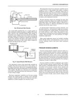
A closed-loop system relies on measurement of the controlled
variable to vary the controller output. Figure 19 shows a block
diagram of a closed-loop system. An example of closed-loop
control would be the temperature of discharge air in a duct
determining the flow of hot water to the heating coils to maintain
the discharge temperature at a controller setpoint.
In an air conditioning system, the controlled variable is
maintained by varying the output of the mechanical equipment
by means of an automatic control loop. A control loop consists
of an input sensing element, such as a temperature sensor; a
controller that processes the input signal and produces an output
signal; and a final control element, such as a valve, that operates
according to the output signal.
ENGINEERING MANUAL OF AUTOMATIC CONTROL
15