Difficult situatioins recognition system for visually impaired aid using a mobile kinect
Bạn đang xem bản rút gọn của tài liệu. Xem và tải ngay bản đầy đủ của tài liệu tại đây (17.91 MB, 76 trang )
HOANG VAN NAM
MINISTRY OF EDUCATION AND TRAINING
HANOI UNIVERSITY OF SCIENCE AND TECHNOLOGY
---------------------------------------
Hoang Van Nam
COMPUTER SCIENCE
DIFFICULT SITUATIONS RECOGNITION SYSTEM FOR
VISUALLY-IMPAIRED AID USING A MOBILE KINECT
MASTER THESIS OF SCIENCE
COMPUTER SCIENCE
2014B
Ha Noi – 2016
MINISTRY OF EDUCATION AND TRAINING
HANOI UNIVERSITY OF SCIENCE AND TECHNOLOGY
--------------------------------------Hoang Van Nam
DIFFICULT SITUATIONS RECOGNITION SYSTEM FOR
VISUALLY-IMPAIRED AID USING A MOBILE KINECT
Department :
COMPUTER SCIENCE
MASTER THESIS OF SCIENCE
…......................................
SUPERVISOR :
1. Dr. Le Thi Lan
Ha Noi – 2016
CỘNG HÒA XÃ HỘI CHỦ NGHĨA VIỆT NAM
Độc lập – Tự do – Hạnh phúc
BẢN XÁC NHẬN CHỈNH SỬA LUẬN VĂN THẠC SĨ
Họ và tên tác giả luận văn : …………………………………........……………..
Đề tài luận văn: ………………………………………….....……………...............….
Chuyên ngành:……………………………...…………………........................…..........
Mã số SV:………………………………….. …………………....................................…...
Tác giả, Người hướng dẫn khoa học và Hội đồng chấm luận văn xác
nhận tác giả đã sửa chữa, bổ sung luận văn theo biên bản họp Hội đồng
ngày….........................………… với các nội dung sau:
……………………………………………………………………………………………………..…………
…………………………………………………………………………………………..…………………………
…………………………………………………………………………..…………………………………………
…………………………………………………………..…………………………………………………………
…………………………………………..…………………………………………………………………………
…………………………..……………………………………………………………………………………..
Ngày
Giáo viên hướng dẫn
CHỦ TỊCH HỘI ĐỒNG
tháng
năm
Tác giả luận văn
Declaration of Authorship
I, Hoang Van Nam, declare that this thesis titled, ’Difficult situations recognition for
visual-impaired aid using mobile Kinect’ and the work presented in it are my own. I
confirm that:
This work was done wholly or mainly while in candidature for a research degree
at this University.
Where any part of this thesis has previously been submitted for a degree or any
other qualification at this University or any other institution, this has been clearly
stated.
Where I have consulted the published work of others, this is always clearly attributed.
Where I have quoted from the work of others, the source is always given. With
the exception of such quotations, this thesis is entirely my own work.
I have acknowledged all main sources of help.
Where the thesis is based on work done by myself jointly with others, I have made
clear exactly what was done by others and what I have contributed myself.
Signed:
Date:
i
HANOI UNIVERSITY OF SCIENCE AND TECHNOLOGY
Abstract
International Research Institute MICA
Computer Vision Department
Master of Science
Difficult situations recognition for visual-impaired aid using mobile Kinect
by Hoang Van Nam
By 2014, according to figures from some organization, here are more than one million
people in the Vietnam living with sight loss, about 1.3% of Vietnamese people. Although
the big impact to the daily living, especially with the ability to move, read, communicate
with another, only a small percentage of blind or visually impaired people live with
assistive device or animal such as a dog guide. Motivated by the significant changes in
technology have take place in the last decade, especially in the introduction of varies
types of sensors as well as the development in the field of computer vision, I present
in this thesis a difficult situations recognition system for visually impaired aid using a
mobile Kinect. This system is based on data captured from Kinect and using computer
vision technique to detect obstacle. At the current prototype, I only focused on detecting
obstacle in the indoor environment like public building and two types of obstacle will
be exploited: general obstacle in the moving way and staircases-which causes a big
dangerous to the visually impaired people. The 3D imaging techniques were used to
detect the general obstacle including: plane segmentation, 3D point clustering and the
mixed strategy between depth and color image is used to detect the staircase based on
detecting the stair edges and its structure. The system is very reliable with the detection
rate is about 82.9% and the time to process each frame is 493 ms.
Acknowledgements
I am so honor to be here the second time, in one of the finest university in Vietnam to
write those grateful words to people who have been supporting, guiding me from the
very first moment when I was a university student until now, when I am writing my
master thesis.
I am grateful to my supervisor, Dr. Le Thi Lan, whose expertise, understanding, generous guidance and support made it possible for me to work on a topic that was of great
interest to me. It was a pleasure to work with her.
Special thanks to Dr. Tran Thi Thanh Hai, Dr. Vu Hai and Dr. Nguyen Thi Thuy
(VNUA) and all of the members in the Computer Vision Department, MICA Institute
for their sharp comments, guidance for my works which helps me a lot in how to study
and to do research in right way and also the valuable advices and encouragements that
they gave to me during my thesis.
I would like to express my gratitude to Prof. Veelaert Peter, Dr. Luong Quang Hiep
and Mr. Michiel Vlaminck at Ghent University, Belgium for their supporting. It’s been
a great honor to cooperate and work with them.
Finally, I would especially like to thank my family and friends for their continues love,
support they have given me through my life, helps me pass through all the frustrating,
struggling, confusing. Thanks for everything that helped me get to this day.
Hanoi, 19/02/2016
Hoang Van Nam
iii
Contents
Declaration of Authorship
i
Abstract
ii
Acknowledgements
iii
Contents
iv
List of Figures
vi
List of Tables
ix
Abbreviations
x
1 Introduction
1.1 Motivation . . . . . . . . . . . . . . . . . . .
1.2 Definition . . . . . . . . . . . . . . . . . . . .
1.2.1 Assistive systems for visually impaired
1.2.2 Difficult situations . . . . . . . . . . .
1.2.3 Mobile Kinect . . . . . . . . . . . . . .
1.2.4 Environment Context . . . . . . . . .
1.3 Difficult Situations Recognition System . . .
1.4 Thesis Contributions . . . . . . . . . . . . . .
. . . .
. . . .
people
. . . .
. . . .
. . . .
. . . .
. . . .
.
.
.
.
.
.
.
.
.
.
.
.
.
.
.
.
.
.
.
.
.
.
.
.
.
.
.
.
.
.
.
.
.
.
.
.
.
.
.
.
.
.
.
.
.
.
.
.
.
.
.
.
.
.
.
.
.
.
.
.
.
.
.
.
.
.
.
.
.
.
.
.
.
.
.
.
.
.
.
.
.
.
.
.
.
.
.
.
.
.
.
.
.
.
.
.
1
1
2
2
3
5
11
12
13
2 Related Works
14
2.1 Assistive systems for visually impaired people . . . . . . . . . . . . . . . . 14
2.2 RGB-D based assistive systems for visually impaired people . . . . . . . . 18
2.3 Stair Detection . . . . . . . . . . . . . . . . . . . . . . . . . . . . . . . . . 19
3 Obstacle Detection
3.1 Overview . . . . . . . . . . . . .
3.2 Data Acquisition . . . . . . . . .
3.3 Point Cloud Registration . . . .
3.4 Plane Segmentation . . . . . . .
3.5 Ground & Wall Plane Detection
.
.
.
.
.
iv
.
.
.
.
.
.
.
.
.
.
.
.
.
.
.
.
.
.
.
.
.
.
.
.
.
.
.
.
.
.
.
.
.
.
.
.
.
.
.
.
.
.
.
.
.
.
.
.
.
.
.
.
.
.
.
.
.
.
.
.
.
.
.
.
.
.
.
.
.
.
.
.
.
.
.
.
.
.
.
.
.
.
.
.
.
.
.
.
.
.
.
.
.
.
.
.
.
.
.
.
.
.
.
.
.
.
.
.
.
.
25
25
26
27
30
32
Contents
3.6
3.7
.
.
.
.
.
.
.
.
.
.
.
.
.
.
.
.
.
.
.
.
.
.
.
.
.
.
.
.
.
.
.
.
.
.
.
.
.
.
.
.
.
.
.
.
.
.
.
.
.
.
.
.
.
.
.
.
.
.
.
.
.
.
.
.
.
.
.
.
.
.
.
.
.
.
.
.
.
.
.
.
.
.
.
.
.
.
.
.
.
.
.
.
.
.
.
.
.
.
.
.
.
.
.
.
.
.
.
.
.
.
.
.
.
.
.
.
.
.
.
.
.
.
.
.
.
.
.
.
.
.
.
.
.
.
.
.
.
.
.
.
32
34
34
35
45
46
48
4 Experiments
4.1 Dataset . . . . . . . . . . . . . . . . . .
4.2 Difficult situation recognition evaluation
4.2.1 Obstacle detection evaluation . .
4.2.2 Stair detection evaluation . . . .
.
.
.
.
.
.
.
.
.
.
.
.
.
.
.
.
.
.
.
.
.
.
.
.
.
.
.
.
.
.
.
.
.
.
.
.
.
.
.
.
.
.
.
.
.
.
.
.
.
.
.
.
.
.
.
.
.
.
.
.
.
.
.
.
.
.
.
.
.
.
.
.
.
.
.
.
49
49
51
51
53
3.8
Obstacle Detection . . . . . . . . . .
Stair Detection . . . . . . . . . . . .
3.7.1 Stair definition . . . . . . . .
3.7.2 Color-based stair detection .
3.7.3 Depth-based stair detection .
3.7.4 Result fusion . . . . . . . . .
Obstacle information representation
v
.
.
.
.
.
.
.
5 Conclusions and Future Works
58
5.1 Conclusions . . . . . . . . . . . . . . . . . . . . . . . . . . . . . . . . . . . 58
5.2 Future Works . . . . . . . . . . . . . . . . . . . . . . . . . . . . . . . . . . 59
6 Publications
60
Bibliography
61
List of Figures
1.1
1.2
1.3
1.4
1.5
1.6
1.7
1.8
1.9
1.10
1.11
1.12
1.13
1.14
1.15
1.16
2.1
2.2
2.3
2.4
2.5
2.6
A Comprehensive Assistive Technology (CAT) Model provided by [12] .
A model for activities attribute and mobility provided by [12] . . . . . .
Distribution of frequencies of head-level accidents for blind people [18] .
Distribution of frequencies of tripping resulting a fall [18] . . . . . . . .
A typical example of depth image (A) raw depth image, (B) depth image
is visualized by jet color map and the colorbar shows the real distance
with each color value, (C) Reconstructed 3D scene . . . . . . . . . . . .
A stereo images that taken from OpenCV library and the calculated depth
image (A) left image, (B) right image, (C) depth image (disparity map)
Some existed stereo camera. From left to right: Kodak stereo camera,
View-Master Personal stereo camera, ZED, Duo 3D Sensor . . . . . . .
Time of flight systems from [3] . . . . . . . . . . . . . . . . . . . . . . .
Some ToF cameras. From left to right: DepthSense, Fotonic, Microsoft
Kinect v2 . . . . . . . . . . . . . . . . . . . . . . . . . . . . . . . . . . .
Structured light cameras. From left to right: PrimeSense, Microsoft
Kinect v1 . . . . . . . . . . . . . . . . . . . . . . . . . . . . . . . . . . .
Structured light systems from [3] . . . . . . . . . . . . . . . . . . . . . .
Figure from [16], (A) raw IR image with pattern, (B) depth image . . .
Figure from [16] (A) Errors for structured light cameras, (B) Quantization
errors in different distances of a door: 1m, 3m, 5m . . . . . . . . . . . .
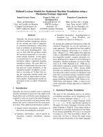
Prototype of system using mobile Kinect, (A) Kinect with battery and
belt, (B) Backpack with laptop (C)Mobile Kinect is mounted on human
body . . . . . . . . . . . . . . . . . . . . . . . . . . . . . . . . . . . . . .
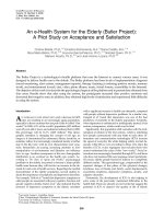
Two different environments that I tested with (A) Our office build (B)
Nguyen Dinh Chieu secondary school . . . . . . . . . . . . . . . . . . . .
Prototype of our obstacle detection and warning system . . . . . . . . .
Robot-Assisted Navigation from [17] (A) RFID tag, (B) Robot (C) Navigation . . . . . . . . . . . . . . . . . . . . . . . . . . . . . . . . . . . . .
NXT Robot System from [6] (A) The system’s Block Diagram, (B) NXT
Robot . . . . . . . . . . . . . . . . . . . . . . . . . . . . . . . . . . . . .
Mobile robot from [22] [21] . . . . . . . . . . . . . . . . . . . . . . . . .
BrainPort vision substitution device [32] . . . . . . . . . . . . . . . . . .
Obstacle detection process from [30] . . . . . . . . . . . . . . . . . . . .
Stair detection from [26] (A) Input image (B)(C)Frequency as a output
of Gabor filter (D)Stair detection result . . . . . . . . . . . . . . . . . .
vi
.
.
.
.
3
4
4
5
.
6
.
7
.
.
7
8
.
8
.
.
.
8
9
9
. 10
. 11
. 12
. 13
. 15
.
.
.
.
16
16
18
20
. 21
List of Figures
A near-approach for stair detection in [13] (A) Input image with detected
stair region, (B) Texture energy, (C)Input image with detected lines are
stair candidates, (D)Optical flow maps in this image, there is a significant
changing in the line in the edge of stair . . . . . . . . . . . . . . . . . .
2.8 Example of segmentation and classification in [24] . . . . . . . . . . . .
2.9 Stair modeling(left) and features in each plane [24] . . . . . . . . . . . .
2.10 Stair detection algorithm proposed in [29] (A) Detected line in the edge
image (using color infomation) (B) Depth profiles in each line (red line:
pedestrian crosswalk, blue: down stair, green: upstair) . . . . . . . . . .
vii
2.7
3.1
3.2
3.3
3.4
3.5
3.6
3.7
3.8
3.9
3.10
3.11
3.12
3.13
3.14
3.15
3.16
3.17
3.18
3.19
3.20
3.21
3.22
3.23
3.24
3.25
3.26
3.27
Obstacle Detection Flowchart . . . . . . . . . . . . . . . . . . . . . . .
Kinect mounted on body . . . . . . . . . . . . . . . . . . . . . . . . . . .
Coordinate Transformation Process . . . . . . . . . . . . . . . . . . . . .
Kinect Coordinate . . . . . . . . . . . . . . . . . . . . . . . . . . . . . .
Point Cloud rotation using normal vector of ground plane (while arrow):
left: before rotating, right: after rotating . . . . . . . . . . . . . . . . . .
Normal vector estimation algorithms [15] (a) Normal vector of the center
point can be calculated by a cross product of two vectors of four neighbor
points (red), (b) Normal vector estimation in a scene . . . . . . . . . .
Plane segmentation result using algorithm proposed in [15]. Each plane
is represented by a distinctive color. . . . . . . . . . . . . . . . . . . . .
Detected Ground and Walls plane (ground: blue, wall: red) . . . . . . .
Human Segmentation Data by Microsoft Kinect SDK (a) Color Image,
(b) Human Mask . . . . . . . . . . . . . . . . . . . . . . . . . . . . . .
Detected Obstacles (a) Color Image, (b) Detected Obstacles . . . . . .
Model of stair . . . . . . . . . . . . . . . . . . . . . . . . . . . . . . . . .
Coordinate transformation models from [7] . . . . . . . . . . . . . . . .
Projective chirping: a) A real world object that generate a projection
with ”chirping” - ”periodicity-in-perspective” b) Center raster of image
c) Best fit projective chirp . . . . . . . . . . . . . . . . . . . . . . . . . .
A pin-hole camera model with stair . . . . . . . . . . . . . . . . . . . . .
A vertical Gabor filter kernel. . . . . . . . . . . . . . . . . . . . . . . . .
Gabor filter applied on a color image (a) Original (b) Filtered Image. .
Thresholding the grayscale image (a) Original (b) Thresholded Image.
Example of thinning image using morphological. . . . . . . . . . . . . .
Thresholding the grayscale image (a) Original (b) Thresholded Image.
Six points vote for a line will make an intersection in Hough space, this
intersection has higher intensity than neighbor pixels. . . . . . . . . . .
Hough space (a) Line in the original space (b) Three curves vote for this
line in Hough space. . . . . . . . . . . . . . . . . . . . . . . . . . . . . .
Hough space on stair image (a) Original image (b) Hough space. . . . .
Chirp pattern detection (a) Hough space (b) Original image with detected
chirp pattern. . . . . . . . . . . . . . . . . . . . . . . . . . . . . . . . .
Point cloud of stair (a) Original color image (b)Point cloud data created
from color and depth image. . . . . . . . . . . . . . . . . . . . . . . . .
Detected steps . . . . . . . . . . . . . . . . . . . . . . . . . . . . . . . .
Detected planes. . . . . . . . . . . . . . . . . . . . . . . . . . . . . . . .
Detected stair on point cloud. . . . . . . . . . . . . . . . . . . . . . . . .
. 22
. 23
. 23
. 24
.
.
.
.
26
27
28
29
. 30
. 31
. 31
. 33
.
.
.
.
34
34
35
36
.
.
.
.
.
.
.
38
38
39
40
40
41
42
. 42
. 43
. 43
. 44
.
.
.
.
45
46
47
47
List of Figures
viii
3.28 Obstacle position quantization for sending warning message to visually
impaired people. . . . . . . . . . . . . . . . . . . . . . . . . . . . . . . . . 48
4.1
4.2
4.3
4.4
4.5
4.6
Depth image encoding (A) Original, (B) Visualized Image (C) Encoded
Image. . . . . . . . . . . . . . . . . . . . . . . . . . . . . . . . . . . . . . .
Detection time of each step in our proposed method. . . . . . . . . . . . .
Example stair image to evaluation (A)Positive sample from MICA dataset
(B) Negative sample from MICA dataset (C) Positive sample from MONASH
dataset (D) Negative sample from MONASH dataset. . . . . . . . . . . .
Detected stair in Tian’s based method (A-F) and detected stair in my
proposal method (G-I) (A) Color image (B) Depth image (C) Edges (D)
Line segments (E) Detected concurrent lines (F) Depth values on detected
lines (G) Detected stair with blue lines are false stair edge and green
lines are stair edge (H) Edges Image, (I) Detected peaks in Hough map
corresponding to lines in Figure G. . . . . . . . . . . . . . . . . . . . . . .
Miss detection in Tian’s based method because of missed depth on stair(AF) and detected stair in my proposed method (G-I). . . . . . . . . . . . .
Miss detection in Tian’s based method because of missed depth on stair(AF) and detected stair in my proposed method (G-I). . . . . . . . . . . . .
50
52
54
55
56
57
List of Tables
2.1
Comparison between assistive robot and wearable device . . . . . . . . . . 14
4.1
4.2
4.3
4.4
4.5
4.6
Database specifications. . . . . . . . . . . . . . . . . . . . . . . . . . . .
Pixel level evaluation result (TP,FP,FN: million pixels). . . . . . . . . .
Object level evaluation result (TP,FP,FN: objects). . . . . . . . . . . . .
Stair dataset for evaluation . . . . . . . . . . . . . . . . . . . . . . . . .
Stair detection result of the proposed method on different datasets . . .
Comparison of the proposed method and the method of Tian et al. [29]
on MICA dataset . . . . . . . . . . . . . . . . . . . . . . . . . . . . . . .
ix
.
.
.
.
.
50
52
52
53
53
. 55
Abbreviations
PCL
Point Cloud Library
CAT
Comprehensive Assistive Technology
TDU
Tongue Display Unit
IR
Infrared
OpenCV
Open Computer Vision
RGB
Red Green Blue
RGB-D
Red Green Blue and Depth
ToF
Time of Flight
x
Chapter 1
Introduction
1.1
Motivation
According to the official statistic of National Eye Hospital in 2002, Vietnam has about
900.000 blind people, including about 400.000 who are totally blind. By 2014, according
to figures from some organizations, the number of blind people in Vietnam is about 1,2
to 1,4 million people, it’s still a large number in comparison with other countries. In
the worldwide, the visually impaired population is estimated to number in excess of 285
million by the investigation of World Health Organization (August 2014)1 . About 90% of
them live in developing countries with low-income settings. Visually impaired has made
a big impact in their daily living. Especially they can not read the document, the ability
to move and to communicate with other people is compromised because the information
is received primarily through vision. All of the above things have led blindness become
the public heath problem in all over the world.
Nowadays, with the significant developing in the technology, lots of assistive devices
has been released in order to help visually impaired people in daily life. But although
many researchers and companies are concerned with making better and cheap device
to improve the comfort of visually impaired people, the research in this field still remains many unsolved issues and in general, those devices still cannot replace traditional
methods such as the white cane or guided dog.
Take the motivation on the significant changes in technology have take place in the last
decade, especially in the introduction of varies types of sensors as well as the development
in the field of computer vision, my thesis aims to build a prototype of system to help
visually impaired people avoid the obstacle in the environment using Kinect sensor.
1
/>
1
Chapter 1. Introduction
2
With the Kinect, the benefit is that we can make a reliable system by using depth and
color information to detect the obstacle with an affordable price. In my thesis, due to
the lack of time, I only focus on indoor environment, more specifically in the public
building such as apartment or office in order to detect some general objects encountered
on the moving way and stair which may cause danger to the visually impaired people.
My thesis is organized as follows:
First, I shall give some definitions in the context of my work and the contributions in
this thesis.
In chapter 2, I shall review briefly some other works that related to my system such
as existing assistive devices, obstacle detection algorithms/systems, its advantages and
disadvantages.
In chapter 3, a framework for obstacle detection will be developed and I shall present
the details of each module and also the entire system, analyzing and assessing them.
In the next chapter, I shall give some experiments results of my system, including how
to prepare the dataset, how to make an evaluation and the final results.
In the final chapter, I end this work by giving some conclusions and future works to
make the system more complete and effective.
1.2
Definition
1.2.1
Assistive systems for visually impaired people
According to [12], assistive systems for visually impaired people can be understood as
an equipment, devices or systems which can be used to overcome the gap between a
disabled person wants to do and what the social allows them to do. In short, such
kind of system must be able to help the visually impaired people to do the things that
normal people can do. And this system can be model by the Comprehensive Assistive
Technology (CAT) Model as shown in Fig 1.1. The top level of this model consist of
four components that can be used to define all assistive technology systems:
• Context (in which the assistive technology will be used).
• Person (what kind of user can use this system)
• Activities (what activities that assistive system can help the visually impaired
people, can be seen more clearly in Fig 1.2)
Chapter 1. Introduction
3
• Assistive Technology (technology will be used to make a system)
Most of the existing systems are aimed at solving one specific aspect of each branch in
the model: work on bounded defined context, with some certain types of users to help
them in specific activities in daily life. In the framework of my master thesis, to simplify
the system, I just focused on some certain aspects of this model and I will explain in
detail in the next sections. In short, I applied my system with the local settings of
context, in a small public building such as office, department and the users are the
visually impaired students at the Nguyen Dinh Chieu Secondary school to help them
avoid obstacles in a moving way.
Local settings
Culture &
Social context
National context
Context
Characteristics
Comprehensive
Assistive
Technology
model
Person
Activities
Assistive Technology
Attitudes
Social aspects
Activity specification
Design issues
System technology issues
End user issues
Figure 1.1: A Comprehensive Assistive Technology (CAT) Model provided by [12]
1.2.2
Difficult situations
Fig 1.2 shows detail information of activities branch in the model CAT (see Fig 1.1).
As shown in the figure, there are a lot of services that can be used in assistive systems
for visually impaired people such as mobility, daily living, cognitive activities, education
and employment, recreational activities, communication and access to information. But
most of exist works focus on the mobility component in the activities model because of
its important role for visually impaired people daily life.
Chapter 1. Introduction
4
Reaching and lifting
Sitting and standing
Short distance locomotion
inside & outside
Mobility
Long & medium distance
locomotion
Movement on ramps,
slopes, stairs & hills
Our Focus
Daily living
Obstacle avoidance
Activities
Cognitive activities
Navigation and orientation
Education and Employment
Sitting and standing
Recreational activities
Communication & Access to information
Access to environment
Figure 1.2: A model for activities attribute and mobility provided by [12]
According to the survey of R.Manduchi [18] in 2011 with 300 respondents who are
legally blind or blind, there were half of the respondents said that they had an headlevel accident at least once in a week and about 30% respondents fell down at least once
a month (see Fig 1.3 and Fig 1.4). Therefore, helping visually impaired people in the
moving process is always an interested topic for researchers, social organizations and
companies. In fact, many products have been released, and also have some particular
success like the system proposed in [11], [10], [1] and [4].
Figure 1.3: Distribution of frequencies of head-level accidents for blind people [18]
Chapter 1. Introduction
5
Figure 1.4: Distribution of frequencies of tripping resulting a fall [18]
In the context of my thesis, I aim to develop a system which can detect the obstacles
in visually impaired people’s moving way which are the main cause of the accidents
mentioned above. The scenario in this project is that visually impaired people want to
move on the hallway inside a public building, so they need to avoid obstacles including
moving or static objects and to go up/down the stair. Obstacle in my case can be defined
as objects laying on the ground or in front of the visually impaired people that he/she
can be harmed while moving if encountered these objects. Although obstacle’s class is
very important with the visually impaired people to distinguish which is more dangerous
and which is not but in my work, I just try to detect obstacle in the scene without saying
its name (make a classification). And within the framework of this thesis, I also focus on
detection another special object that often appears in the building and is very dangerous
for the visually impaired people, that is the stair. Moreover, the proposed system will
only give a warning to the blind people using Tongue Display Unit (TDU) which has
been already developed by Thanh-Huong Nguyen in 2013 [23]. In brief, my proposed
system aims to solve two aspects of mobility component of the activities model (see
Fig. 1.2): obstacle avoidance and movement on ramps, slopes, stair & hill and with
the second aspect, the current system just stop at the level of given warning distance of
stairs to the visually impaired people in order to assist them in going up/down stairs.
1.2.3
Mobile Kinect
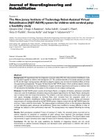
1. Introduction To assist visually impaired persons in those difficult situations, in
my thesis, I proposed using a Kinect sensor to capture the information of the environment in order to detect obstacles if they appear. There are a lot of advantages
when using Kinect in this system since it is a popular RGB-D camera with cheap
price. But firstly, I will give some brief information about the depth camera where
Kinect is the typical example.
Chapter 1. Introduction
6
Depth camera is actually a sensor which has the capacity to provide depth information (depth image or depth map). A depth map is an image that contains
information relating to the distance of the surface of scene objects from a viewpoint, for example in the Fig. 1.5. An intensity value of each pixel in a depth
map represents a distance from a point in the object to the camera. Therefore,
3D information of the scene can be reconstructed by using depth image (as shown
in Fig. 1.5-C). The benefit of the depth image that is not affected by lighting
conditions.
(a)
(b)
(c)
Figure 1.5: A typical example of depth image (A) raw depth image, (B) depth image
is visualized by jet color map and the colorbar shows the real distance with each color
value, (C) Reconstructed 3D scene
In recent years, with the development of technology, especially in the field of
sensor fabrication industry, there are a lot of cameras have been placed on the
market which is capable of capturing the depth information. Those devices can be
separated into several groups by used technology such as stereo camera: ZED, for
example, Time-of-Flight (ToF) like ZCam, the structured light camera like Kinect,
long range 3D camera. Each device has it own advantages, disadvantages and only
suitable for a particular use case.
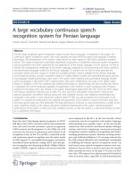
2. Stereo Camera
Stereo camera is the kind of camera was used in the robotics since its early days.
Take the ideas of human binocular vision, it contains two or more cameras with
precisely known relative offsets. Depth information can be calculated by matching
similar point in the overlapped region between images. Hence, 3D distance to
matching points can be determined using triangulation like illustrated in Fig 1.6.
However, the camera is used in this case is still the color camera. As a result, it is
still affected by the changing of lighting conditions. On the other hand, the depth
image is calculated by matching algorithms, so it works very poorly when the
scene is texture-less, for example image of wall, building,. There are many stereo
cameras that are available on the market due to the ease of making such as Kodak
Chapter 1. Introduction
7
stereo camera, View-Master Personal stereo camera, ZED2 , Duo 3D Sensor3 , as
illustrated in Fig 1.7.
(a)
(b)
(c)
Figure 1.6: A stereo images that taken from OpenCV library and the calculated
depth image (A) left image, (B) right image, (C) depth image (disparity map)
Figure 1.7: Some existed stereo camera. From left to right: Kodak stereo camera,
View-Master Personal stereo camera, ZED, Duo 3D Sensor
3. Time of Flight (ToF) camera
Time of Flight (ToF) cameras use the same principle as laser radar, which is
instead of transmitting a single beam, short pulses of Infrared(IR) light is sent.
The camera will get the return time from pixels across its field of view. And the
distance was measured by comparing the phase of the modulated return pulses
with those emitted by the laser (Fig 1.8). But ToF cameras is also suffered from
similar limitations as a ime of flight sensors, including ambiguity of measurements,
multiple reflection, sensitivity to material reflectance, background lighting and do
not operate well outdoors in strong sunlight. Some of the popular ToF cameras
can be listed such as: DepthSense4 , Fotonic5 , Microsoft Kinect v2 (see Fig 1.9)
4. Structured light camera
Structured light camera is another approach to measure depth information by
using “structured light”, which is a pattern of light such as array of lines. The
scene will be viewed at an angle like illustrating in the Fig 1.11. If the pattern is
projected onto a flat wall, the camera will see straight lines but if the scene is very
complex then it will see a more complex profile. By analyzing this profiles across
2
/>
4
/>5
/>3
Chapter 1. Introduction
8
Figure 1.8: Time of flight systems from [3]
Figure 1.9: Some ToF cameras. From left to right: DepthSense, Fotonic, Microsoft
Kinect v2
the field to map, depth information can be calculated. With traditional method,
structured lights is grids or arrays of lines but it’s affected by a noise. So that, in
some newer devices such as PrimeSense or Microsoft Kinect v1 (see Fig 1.10), a
codes will be added in to a light to make the camera is almost zero repetition across
the scene. The Kinect v1 uses a randomly distributed speckled pattern and each
speckle looks differently flat at different distance, due to a special lens as can be
seen in the Fig 1.12. But this kind of depth sensor also have some limitations such
as the errors grow with the square of the distance to objects, strong quantization
effects (see Fig) and some limitations that similar with ToF system like sensitivity
to material reflectance, do not operate well in strong sunlight.
Figure 1.10: Structured light cameras. From left to right: PrimeSense, Microsoft
Kinect v1
Chapter 1. Introduction
9
Figure 1.11: Structured light systems from [3]
(a)
(b)
Figure 1.12: Figure from [16], (A) raw IR image with pattern, (B) depth image
Chapter 1. Introduction
10
(a)
(b)
Figure 1.13: Figure from [16] (A) Errors for structured light cameras, (B) Quantization errors in different distances of a door: 1m, 3m, 5m
Chapter 1. Introduction
11
5. Mobile Kinect
In my thesis, I used Microsoft Kinect v1 as a capture device of the system due to
its usability and availability. To make Kinect become more flexibility, I have added
some components and making it become “Mobile Kinect”, which is Kinect with a
external battery so it can be moved to anywhere without worrying about electrical
sources (holes, cables) and it is easy to replace this external battery. To attach on
the human body, Kinect has been mounted into a single belt, so that the Kinect
can be fix mounted easily on the body. An other important part of mobile Kinect
is a laptop which plays the role of main processor. It contains a data acquisition
and obstacle detection modules. The reason of choosing laptop because Kinect is
the commercial device and it have been developed for the video game purposes,
so Kinect cannot operate without a PC. And because of the restrictions in Kinect
data cable length, a computer must be placed nearby the Kinect (the whole system
can be seen in Fig 1.14).
(a)
(b)
(c)
Figure 1.14: Prototype of system using mobile Kinect, (A) Kinect with battery and
belt, (B) Backpack with laptop (C)Mobile Kinect is mounted on human body
Officially, Kinect runs with 12V sources provided by an adapter comes with it by
default. In the experiment, it can operate when the voltage drops down to 8.5V
with the running current is about 0.3-0.4A. So I designed battery with 8-packs
AAA batteries of which can provides 8x1.5A=12A. And the time to drop down
from 12V-8.5V is about 1.5-2 hours in our experiment, which mean the mobile
Kinect can runs 1.5-2 hours with the battery.
1.2.4
Environment Context
The environment for development and testing system is public building as mentioned
before. More specifically, I just focus on a specific use case, that is walking along the
corridors of building. There are two major type of corridor in our context, that is
two sides wall and half opening with one side is the glass windows or opened and the
other side is the solid wall. But in our experiment, I aim to develop a system with the
Chapter 1. Introduction
12
half opening corridor because it’s very popular type in public building such as school,
office and some apartment. In the context of my thesis, I tested the system with two
different environments. One is our office building at B1-Hanoi University of Science and
Technology, the others is Nguyen Dinh Chieu secondary school for blind pupils (see Fig
1.15). Because depth data is strongly affected by sun light, so the requirement with
environment is that it must not be lighted too strong (in the shady day or in the two
sides wall building, where the sun light cannot reach to).
The use-case was used is that the user (visually impaired people) want to move to another
place in the building and to do that, he/she must go along the corridor, walk up/down
the stair then move to destination point. Ignoring the problem with path finding, in
my work, I only aim to obstacle avoidance. Obstacles in both cases are the objects that
blocked the moving way such as: distinguisher, trash bin, column, wall and human in
front of the user (can be seen in Fig 1.15).
(a)
(b)
Figure 1.15: Two different environments that I tested with (A) Our office build (B)
Nguyen Dinh Chieu secondary school
1.3
Difficult Situations Recognition System
In conclusion, my entire system to recognize the difficult situations can be demonstrated
as in Fig 1.16. In this case, the prototype system will be fix mounted on the visually
impaired people. To interact with the user, a tactile visual substitution module from
[23] has been used to give the warning about obstacle in front of he/she. The mobile
Kinect will be mounted on the human hip to capture depth and color information. Those
information will be processed by a recognition module in the laptop behind user. After
obstacle has been detected, laptop will send a correspondence command to tactile visual
substitution module in order to give warning message. The message representation has
been integrated into this module and presented in [23]. So my main work is how to send
a correct command to the feedback module.