PRS 27
Bạn đang xem bản rút gọn của tài liệu. Xem và tải ngay bản đầy đủ của tài liệu tại đây (203.9 KB, 26 trang )
48. General Purpose Pseudo Random Sequence Generator
Pseudo Random Sequence Generator
PRS v3.1
Copyright © 2000-2004. Cypress MicroSystems, Inc. All Rights Reserved.
CY8C29/27/24/22xxx Data Sheet
PSoC™ Blocks
API Memory (Bytes)
Digital
Analog CT
Analog SC
Flash
RAM
Pins (per
External I/O)
8-bit
1
0
0
41
0
1
16-bit
2
0
0
54
0
1
24-bit
3
0
0
82
0
1
32-bit
4
0
0
93
0
1
8-bit
1
0
0
41
0
1
16-bit
2
0
0
54
0
1
24-bit
3
0
0
82
0
1
32-bit
4
0
0
93
0
1
Resources
CY8C29/27/24/22xxx
CY8C26/25xxx
Features and Overview
• 2- to 8-, 16-, 24- or 32-bit general purpose pseudo-random number generator uses one, two, three or
•
•
•
•
four PSoC blocks, respectively
Data input clocking up to 48 MHz
Programmable polynomial and seed values
Serial output bit stream
Computed pseudo-random number can be read directly from the LFSR
The PRS User Module is a modular linear feedback shift register (LFSR) that generates a pseudo random
bit stream. The polynomial and starting seed values can be specified to define its output number
sequence.
September 7, 2004
1
User Module Data Sheet
1
X
0
X
1
n-3
X
n-4
2
n-2
X
n-3
n-1
X
n-2
n
X
n-1
Polynomial
Register
Shift
Register
0
1
n-3
n-2
n-1
2
n-3
n-2
n-1
Output
0
2
0
1
Seed
Register
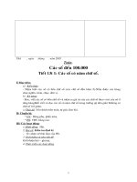
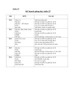
PRS Block Diagram, Data Path width n = 8, 16, 24 or 32
2
September 7, 2004
General Purpose Pseudo Random Sequence Generator
Functional Description
The PRS User Module employs from one to four digital PSoC blocks, each contributing 8 bits to the total
resolution. It implements a modular 2- to 8-, 16-, 24- or 32-bit linear feedback shift register, LFSR, that
generates a pseudo-random bit stream. The Shift, Polynomial, Seed, and Control registers, of the PRS
PSoC blocks, are used to define and control the generation of the pseudo-random bit sequence.
The configuration of the underlying connective hardware, of the digital PSoC blocks, coordinate the
operation of the PSoC blocks as a single PRS User Module. The Polynomial, Shift, and Seed registers
refer to the combined registers. The PRSxx_MSB registers form the most significant byte of the register
set and the PRSxx_LSB registers form the least significant byte. For example, the 32-bit PRS Polynomial
register is composed of the PRS32_MSB, PRS32_ISB2, PRS32_ISB1, and PRS32_LSB Polynomial
registers.
The Shift register computes the LFSR function, the Polynomial register holds the polynomial that defines
the LFSR polynomial, and the Seed register enables initialization of the starting data.
The PRS User Module requires that the Seed and Polynomial registers be initialized, prior to setting the
start bit in the PRS’s Control register.
Writing the seed value into the Seed register, while the PRS start bit is not set, causes the seed value to
be latched into the Shift register, initializing the starting data. Writing the seed value, after the PRS has
been started, has no effect.
The architecture for a simple LFSR uses only a single XOR gate, to add the values of one or more bits and
feed the result back into the least significant bit. The polynomial description for the simple LFSR is defined
as [N, t1, t2,...,tm], where N is the length of the output code in bits and t denotes the tap bit numbers that
are XOR’ed into the feedback summation. For example, the polynomial defined as [32,22,2,1] is a 32-bit
polynomial with taps at bit 32, bit 22, bit 2, and bit 1. The polynomial defined as [8,4,3,2] is an 8-bit
polynomial with taps at bit 8, bit 4, bit 3, and bit 2. Note that the most significant bit is always XOR’ed into
the summation.
The PRS is an LFSR that is implemented using the modular form where there is one XOR gate between
each bit of the shift register. The translation of the simple polynomial to the modular polynomial definition
is given by the notation [N, N-t1, N-t2, …,N-tm]. The 32-bit PRS simple polynomial [32,22,2,1] is translated
to [32,32-22,32-2,32-1] or [32,31,30,10] after re-ordering. The 8-bit PRS simple polynomial [8,4,3,2] is
translated to [8,8-4,8-3,8-2] or [8,6,5,4] after re-ordering. The modular polynomial definition, similar to the
simple polynomial, specifies the length and the tap bits.
For the 32-bit PRS simple polynomial [32,22,2,1], the Polynomial register should be set with the modular
equivalent polynomial of [32,31,30,10], which is specified as 1110 0000 0000 0000 0000 0010 0000 0000b
or E0000200h.
The following table lists simple and modular irreducible polynomials that define 2- to 32-bit pseudorandom number sequences (including 8, 16, and 24 bits). Note that the table is not complete, in that only
one of the many polynomials is specified.
Simple and Modular Irreducible Polynomials
Number of
Bits
Code Length
Simple Form
Polynomial
Modular Form
Polynomial
2
3
[2,1]
[2,1]
3
7
[3,1]
[3,2]
4
15
[4,1]
[4,3]
5
31
[5,4,3,2]
[5,3,2,1]
September 7, 2004
3
User Module Data Sheet
Simple and Modular Irreducible Polynomials (continued)
Number of
Bits
Code Length
Simple Form
Polynomial
Modular Form
Polynomial
6
63
[6,5,2,1]
[6,5,4,1]
7
127
[7,6,5,2]
[7,5,2,1]
8
255
[8,4,3,2]
[8,6,5,4]
9
511
[9,6,4,3]
[9,6,5,3]
10
1,023
[10,8,3,2]
[10,8,7,2]
11
2,047
[11,8,5,2]
[11,9,6,3]
12
4,095
[12,6,4,1]
[12,11,8,6]
13
8,191
[13,4,3,1]
[13,12,10,9]
14
16,383
[14,12,2,1]
[14,13,12,2]
15
32,767
[15,13,10,9]
[15,6,5,2]
16
65,535
[16,12,3,1]
[16,15,13,4]
17
131,071
[17,3,2,1]
[17,16,15,14]
18
262,143
[18,10,7,5]
[18,13,11,8]
19
524,287
[19,5,2,1]
[19,18,17,14]
20
1,048,575
[20,9,5,3]
[20,17,15,11]
21
2,097,151
[21,14,7,2]
[21,19,14,7]
22
4,194,303
[22,9,5,1]
[22,21,17,13]
23
8,388,607
[23,17,11,5]
[23,18,12,5]
24
16,777,215
[24,7,2,1]
[24,23,22,17]
25
33,554,431
[25,3,2,1]
[25,24,23,22]
26
67,108,863
[26,6,2,1]
[26,25,24,20]
27
134,217,727
[27,5,2,1]
[27,26,25,22]
28
268,435,455
[28,13,11,9,5,3]
[28,25,23,19,17,15]
29
536,870,911
[29,20,11,2]
[29,27,18,9]
30
1,073,741,823
[30,23,2,1]
[30,29,28,7]
31
2,147,483,647
[31,29,21,17]
[31,14,10,2]
32
4,294,967,295
[32,22,2,1]
[32,31,30,10]
The maximal code length, for an N-bit LFSR pseudo random bit sequence generator, is 2n-1. Zero is the
missing value, as this will result in a terminal condition. The starting seed value must be set to any nonzero value.
The polynomial length tap bit, N, is configured by the PRS PSoC block, as both the feedback and output
bit.
When the seed value and polynomial are initialized, the PRS User Module is started and a rising edge of
the input clock generates the next state in the specified pseudo-random sequence. Tap bit N is output to
the specified output bit stream synchronous with the clock.
Reading the computed pseudo-random number is a two-step process. First, the Shift register is read,
causing the result data to be latched into the Seed register. Then, the result is read directly from the Seed
register. It is advisable to stop the PRS User Module before reading the pseudo-random value, to ensure
that the linear feedback Shift register is not inadvertently clocked while reading the data.
4
September 7, 2004
General Purpose Pseudo Random Sequence Generator
AC Electrical Characteristics
PRS AC Electrical Characteristics
Parameter
Typical
Limit
Units
Conditions and Notes
Maximum input frequency
--
481
MHz
Vdd=5.0V2
Maximum output frequency
--
241
MHz
Vdd=5.0V and 48 MHz input clock
--
123
MHz
Vdd=3.3V and 24 MHz input clock
Electrical Characteristics Notes
1. If the input or output is routed through the global buses, then the frequency is limited to a maximum of 12 MHz.
2. Provided enable signal is always high; otherwise, the limit is 24MHz.
3. Fastest clock available to PSoC blocks is 24 MHz at 3.3V operation.
Placement
The PRS consumes one digital PSoC block per 8 bits of resolution. When more than one block is
allocated, all will be placed consecutively by the Device Editor in order of increasing block number from
least-significant byte (LSB) to most significant (the MSB). Each block is given a symbolic name displayed
by the device editor during and after placement. The API qualifies all register names with user assigned
instance name and block name to provide direct access to the PRS registers through the API include files.
The block names used by the various widths are given in the following table.
PSoC Blocks
8-Bit PRS
16-Bit PRS
24-Bit PRS
32-Bit PRS
1
PRS8
PRS16_LSB
PRS24_LSB
PRS32_LSB
2
--
PRS16_MSB
PRS24_ISB
PRS32_ISB1
3
--
--
PRS24_MSB
PRS32_ISB2
4
--
--
--
PRS32_MSB
Parameters and Resources
Clock
The PRS User Module is clocked by one of 16 possible sources. The Global I/O busses may be used to
connect the clock input to an external pin or a clock function generated by a different PSoC block. The 48
MHz clock, the CPU_32 kHz clock, one of the divided clocks (24V1 or 24V2), or another PSoC block
output can be specified as the clock input.
OutputBitStream
The output may be routed to one of four Global Output buses or disabled.
September 7, 2004
5
User Module Data Sheet
CompareType
Each cycle the PRS compares the value of the Shift register to the value of the Seed register. This
parameter sets the type of compare function to be performed. The possible settings are given in the
following table.
Parameter
Description
Equal
DAC output goes high when Shift register equals seed value.
Less Than or Equal
DAC output goes high when Shift register is less than or equal to seed value.
Less Than
DAC output goes high when Shift register is less than seed value.
CompareOut
The result of the compare operation (see the CompareType parameter, above) produces and active-high
The DAC Output may be routed to one of four Global Ouptut buses or disabled.
ClockSync
In the PSoC devices, digital blocks may provide clock sources in addition to the system clocks. Digital
clock sources may even be chained in ripple fashion. This introduces skew with respect to the system
clocks. These skews are more critical in the CY8C29/27/24/22xxx PSoC device families because of
various data-path optimizations, particularly those applied to the system busses. This parameter may be
used to control clock skew and ensure proper operation when reading and writing PSoC block register
values. Appropriate values for this parameter should be determined from the following table.
ClockSync Value
Use
Sync to SysClk Use this setting for any 24 MHz (SysClk) derived clock source that is divided by two or more.
Examples include VC1, VC2, VC3 (when VC3 is driven by SysClk), 32KHz, and digital PSoC
blocks with SysClk-based sources. Externally generated clock sources should also use this
value to ensure that proper synchronization occurs.
Sync to SysClk*2 Use this setting for any 48 MHz (SysClk*2) based clock unless the resulting frequency is 48
MHz (in other words, when the product of all divisors is 1).
Use SysClk Direct Use when a 24 MHz (SysClk/1) clock is desired. This does not actually perform synchronization but provides low-skew access to the system clock itself. If selected, this option overrides
the setting of the Clock parameter, above. It should always be used instead of VC1, VC2,
VC3 or Digital Blocks where the net result of all dividers in combination produces a 24 Mhz
output.
Unsynchronized Use when the 48 MHz (SysClk*2) input is selected.
Use when unsynchronized inputs are desired. In general this use is advisable only when
interrupt generation is the sole application of the Counter.
Application Programming Interface
The Application Programming Interface (API) routines are provided as part of the user module to allow the
designer to deal with the module at a higher level. This section specifies the interface to each function
together with related constants provided by the “include” files.
Note
6
In this, as in all user module APIs, the values of the A and X register may be altered by calling an
API function. It is the responsibility of the calling function to preserve the values of A and X prior to
the call if those values are required after the call. This “registers are volatile” policy was selected
September 7, 2004
General Purpose Pseudo Random Sequence Generator
for efficiency reasons and has been in force since version 1.0 of PSoC Designer. The C compiler
automatically takes care of this requirement. Assembly language programmers must ensure their
code observes the policy, too. Though some user module API function may leave A and X
unchanged, there is no guarantee they will do so in the future.
8-Bit PRS API
PRS8_Start
Description:
Enables the PRS8 User Module for operation. Before the module is started, the polynomial and seed
values should be initialized.
C Prototype:
void PRS8_Start(void)
Assembler:
call PRS8_Start
Parameters:
None
Return Value:
None
Side Effects:
While the PRS8 is started, a seed value written to the Seed register will not be latched into the Shift
register. The A and X registers may be modified by this or future implementations of this function. The
same is true for all RAM page pointer registers in the Large Memory Model (CY8C29xxx). When necessary, it is the calling function's responsibility to preserve the values across calls to fastcall16 functions.
PRS8_Stop
Description:
Disables the PRS8 User Module.
C Prototype:
void PRS8_Stop(void)
Assembler:
call PRS8_Stop
Parameters:
None
Return Value:
None
Side Effects:
Writing the seed value into the Seed register will latch the seed value into the Shift register. The A and
X registers may be modified by this or future implementations of this function. The same is true for all
RAM page pointer registers in the Large Memory Model (CY8C29xxx). When necessary, it is the calling function's responsibility to preserve the values across calls to fastcall16 functions.
September 7, 2004
7
User Module Data Sheet
PRS8_WriteSeed
Description:
Initializes the PRS8 Shift register with an initial seed value. The user module is stopped while updating
the Shift register with the new seed value. Upon exit, the start state is restored.
C Prototype:
void PRS8_WriteSeed(BYTE bSeed)
Assembler:
mov
A, [bSeed]
call PRS8_WriteSeed
Parameters:
bSeed: 8-bit seed value and is passed in the A register.
Return Value:
None
Side Effects:
The A and X registers may be modified by this or future implementations of this function. The same is
true for all RAM page pointer registers in the Large Memory Model (CY8C29xxx). When necessary, it
is the calling function's responsibility to preserve the values across calls to fastcall16 functions.
PRS8_WritePolynomial
Description:
Loads the Polynomial register with the LFSR function polynomial. The PRS8 User Module is stopped
while the Polynomial register is updated. Upon exit, the start state is restored.
C Prototype:
void PRS8_WritePolynomial(BYTE bPolynomial)
Assembler:
mov
A, [bPolynomial]
call PRS8_WritePolynomial
Parameters:
bPolynomial: 8-bit polynomial value. See the PRS User Module description section for a discussion on
how to set the polynomial value. It is passed in the A register.
Return Value:
None
Side Effects:
The A and X registers may be modified by this or future implementations of this function. The same is
true for all RAM page pointer registers in the Large Memory Model (CY8C29xxx). When necessary, it
is the calling function's responsibility to preserve the values across calls to fastcall16 functions.
PRS8_bReadPRS
Description:
Reads the computed LFSR resultant data. Calling this function while the PRS8 User Module is
clocked, will give inaccurate results.
C Prototype:
BYTE PRS8_bReadPRS(void)
Assembler:
call PRS8_bReadPRS
8
September 7, 2004
General Purpose Pseudo Random Sequence Generator
mov
[bPRSValue], A
Parameters:
None
Return Value:
Value read from the Shift register. It is returned in Accumulator.
Side Effects:
The Seed register will be overwritten with the computed LFSR value. The A and X registers may be
modified by this or future implementations of this function. The same is true for all RAM page pointer
registers in the Large Memory Model (CY8C29xxx). When necessary, it is the calling function's
responsibility to preserve the values across calls to fastcall16 functions.
16-Bit PRS API
PRS16_Start
Description:
Enables the PRS16 User Module for operation. Before the module is started, the polynomial and seed
values should be initialized.
C Prototype:
void PRS16_Start(void)
Assembler:
call PRS16_Start
Parameters:
None
Return Value:
None
Side Effects:
While the PRS16 is started, a seed value written to the Seed register will not be latched into the Shift
register. The A and X registers may be modified by this or future implementations of this function. The
same is true for all RAM page pointer registers in the Large Memory Model (CY8C29xxx). When necessary, it is the calling function's responsibility to preserve the values across calls to fastcall16 functions.
PRS16_Stop
Description:
Disables the PRS16 User Module.
C Prototype:
void PRS16_Stop(void)
Assembler:
call PRS16_Stop
Parameters:
None
Return Value:
None
Side Effects:
Writing the seed value into the Seed register will latch the seed value into the Shift register. The A and
September 7, 2004
9
User Module Data Sheet
X registers may be modified by this or future implementations of this function. The same is true for all
RAM page pointer registers in the Large Memory Model (CY8C29xxx). When necessary, it is the calling function's responsibility to preserve the values across calls to fastcall16 functions.
PRS16_WriteSeed
Description:
Initializes the PRS16 Shift register with an initial seed value. The PRS16 User Module is stopped while
updating the Shift register with the new seed value. Upon exit, the start state is restored.
C Prototype:
void PRS16_WriteSeed(WORD wSeed)
Assembler:
mov
X, [wSeed]
mov
A, [wSeed+1]
call PRS16_WriteSeed
Parameters:
wSeed: 16-bit seed value. MSB is passed in the X register and LSB is passed in the Accumulator.
Return Value:
None
Side Effects:
The A and X registers may be modified by this or future implementations of this function. The same is
true for all RAM page pointer registers in the Large Memory Model (CY8C29xxx). When necessary, it
is the calling function's responsibility to preserve the values across calls to fastcall16 functions.
PRS16_WritePolynomial
Description:
Loads the Polynomial register with the LFSR function polynomial. The PRS16 User Module is stopped
while the Polynomial register is updated. Upon exit, the start state is restored.
C Prototype:
void
PRS16_WritePolynomial(WORD wPolynomial)
Assembler:
mov
X, [wPolynomial]
mov
A, [wPolynomial+1]
call PRS16_WritePolynomial
Parameters:
wPolynomial: 16-bit polynomial value. See the PRS User Module description section for a discussion
on how to set the polynomial value. MSB is passed in the X register and LSB is passed in the Accumulator.
Return Value:
None
Side Effects:
The A and X registers may be modified by this or future implementations of this function. The same is
true for all RAM page pointer registers in the Large Memory Model (CY8C29xxx). When necessary, it
is the calling function's responsibility to preserve the values across calls to fastcall16 functions.
10
September 7, 2004
General Purpose Pseudo Random Sequence Generator
PRS16_wReadPRS
Description:
Reads the computed LFSR resultant data. Calling this function while the PRS16 User Module is
clocked, will give inaccurate results.
C Prototype:
WORD PRS16_wReadPRS(void)
Assembler:
call PRS16_wReadPRS
mov
[wPRSValue], X
mov
[wPRSValue+1], A
Parameters:
None
Return Value:
Value read from the Shift register. MSB is returned in the X registers and LSB is returned in the Accumulator.
Side Effects:
The Seed register will be overwritten with the computed LFSR value. The A and X registers may be
modified by this or future implementations of this function. The same is true for all RAM page pointer
registers in the Large Memory Model (CY8C29xxx). When necessary, it is the calling function's
responsibility to preserve the values across calls to fastcall16 functions.
24-Bit PRS API
PRS24_Start
Description:
Enables the PRS24 User Module for operation. Before the module is started, the polynomial and seed
values should be initialized.
C Prototype:
void PRS24_Start(void)
Assembler:
call PRS24_Start
Parameters:
None
Return Value:
None
Side Effects:
While the PRS24 is started, a seed value written to the Seed register will not be latched into the Shift
register. The A and X registers may be modified by this or future implementations of this function. The
same is true for all RAM page pointer registers in the Large Memory Model (CY8C29xxx). When necessary, it is the calling function's responsibility to preserve the values across calls to fastcall16 functions.
PRS24_Stop
Description:
Disables the PRS24 User Module.
September 7, 2004
11
User Module Data Sheet
C Prototype:
void PRS24_Stop(void)
Assembler:
call PRS24_Stop
Parameters:
None
Return Value:
None
Side Effects:
Writing the seed value into the Seed register will latch the seed value into the Shift register. The A and
X registers may be modified by this or future implementations of this function. The same is true for all
RAM page pointer registers in the Large Memory Model (CY8C29xxx). When necessary, it is the calling function's responsibility to preserve the values across calls to fastcall16 functions.
PRS24_WriteSeed
Description:
Initializes the PRS24 Shift register with an initial seed value. The PRS24 User Module is stopped while
updating the Shift register with the new seed value. Upon exit, the start state is restored.
C Prototype:
void PRS24_WriteSeed(DWORD dwSeed)
Assembler:
mov
X, dwSeed
call PRS24_WriteSeed
Parameters:
dwSeed: 24-bit seed value where MSB is always zero. The X register points to dwSeed. Load address
of the dwSeed into the X register.
Return Value:
None
Side Effects:
The A and X registers may be modified by this or future implementations of this function. The same is
true for all RAM page pointer registers in the Large Memory Model (CY8C29xxx). When necessary, it
is the calling function's responsibility to preserve the values across calls to fastcall16 functions.
PRS24_WritePolynomial
Description:
Loads the Polynomial register with the LFSR function polynomial. The PRS24 User Module is stopped
while the Polynomial register is updated. Upon exit, the start state is restored.
C Prototype:
void PRS24_WritePolynomial(DWORD dwPolynomial)
Assembler:
mov
X, dwPolynomial
call PRS24_WritePolynomial
Parameters:
dwPolynomial: 24-bit polynomial value. See the PRS User Module description section for a discussion
on how to set the polynomial value. The X register points to dwPolynomial. Load address of the
12
September 7, 2004
General Purpose Pseudo Random Sequence Generator
dwSeed into the X register.
Return Value:
None
Side Effects:
The A and X registers may be modified by this or future implementations of this function. The same is
true for all RAM page pointer registers in the Large Memory Model (CY8C29xxx). When necessary, it
is the calling function's responsibility to preserve the values across calls to fastcall16 functions.
PRS24_ReadPRS
Description:
Reads the computed LFSR resultant data. Calling this function while the PRS24 User Module is
clocked, will give inaccurate results.
C Prototype:
void PRS24_ReadPRS(DWORD * pdwPRSValue)
Assembler:
mov
X, [pdwPRSValue]
call PRS24_ReadPRS
Parameters:
pdwPRSValue: Pointer to the buffer to hold the PRS generated value. The X register is loaded with the
address of the return buffer.
Return Value:
PRS generated value is returned in the pdwPRSValue buffer pointed to by the X register.
Side Effects:
The Seed register will be overwritten with the computed LFSR value. The A and X registers may be
modified by this or future implementations of this function. The same is true for all RAM page pointer
registers in the Large Memory Model (CY8C29xxx). When necessary, it is the calling function's
responsibility to preserve the values across calls to fastcall16 functions. Currently, only the IDX_PP
page pointer register is modified.
32-Bit PRS API
PRS32_Start
Description:
Enables the PRS32 User Module for operation. Before the module is started, the polynomial and seed
values should be initialized.
C Prototype:
void PRS32_Start(void)
Assembler:
call PRS32_Start
Parameters:
None
Return Value:
None
Side Effects:
While the PRS32 is started, a seed value written to the Seed register will not be latched into the Shift
September 7, 2004
13
User Module Data Sheet
register. The A and X registers may be modified by this or future implementations of this function. The
same is true for all RAM page pointer registers in the Large Memory Model (CY8C29xxx). When necessary, it is the calling function's responsibility to preserve the values across calls to fastcall16 functions.
PRS32_Stop
Description:
Disables the PRS32 User Module.
C Prototype:
void PRS32_Stop(void)
Assembler:
call PRS32_Stop
Parameters:
None
Return Value:
None
Side Effects:
Writing the seed value into the Seed register will latch the seed value into the Shift register. The A and
X registers may be modified by this or future implementations of this function. The same is true for all
RAM page pointer registers in the Large Memory Model (CY8C29xxx). When necessary, it is the calling function's responsibility to preserve the values across calls to fastcall16 functions.
PRS32_WriteSeed
Description:
Initializes the PRS32 Shift register with an initial seed value. The PRS32 User Module is stopped while
updating the Shift register with the new seed value. Upon exit, the start state is restored.
C Prototype:
void PRS32_WriteSeed(DWORD dwSeed)
Assembler:
mov
X, dwSeed
call PRS32_WriteSeed
Parameters:
dwSeed: 32-bit seed value. The X register points to dwSeed. Load address of the dwSeed into the X
register.
Return Value:
None
Side Effects:
The A and X registers may be modified by this or future implementations of this function. The same is
true for all RAM page pointer registers in the Large Memory Model (CY8C29xxx). When necessary, it
is the calling function's responsibility to preserve the values across calls to fastcall16 functions.
PRS32_WritePolynomial
Description:
Loads the Polynomial register with the LFSR function polynomial. The PRS32 User Module is stopped
while the Polynomial register is updated. Upon exit, the start state is restored.
14
September 7, 2004
General Purpose Pseudo Random Sequence Generator
C Prototype:
void PRS32_WritePolynomial(DWORD dwPolynomial)
Assembler:
mov
X, dwPolynomial
call PRS32_WritePolynomial
Parameters:
dwPolynomial: 32-bit polynomial value. See the PRS User Module description section for a discussion
on how to set the polynomial value. The X register points to dwPolynomial. Load address of the
dwSeed into the X register.
Return Value:
None
Side Effects:
The A and X registers may be modified by this or future implementations of this function. The same is
true for all RAM page pointer registers in the Large Memory Model (CY8C29xxx). When necessary, it
is the calling function's responsibility to preserve the values across calls to fastcall16 functions.
PRS32_ReadPRS
Description:
Reads the computed LFSR resultant data. Calling this function while the PRS32 User Module is
clocked, will give inaccurate results.
C Prototype:
void PRS32_ReadPRS(DWORD * pdwPRSValue)
Assembler:
mov
X, [pdwPRSValue]
call PRS32_ReadPRS
Parameters:
pdwPRSValue: Pointer to the buffer to hold the PRS generated value. The X register is loaded with the
address of the return buffer.
Return Value:
PRS generated value is returned in the pdwPRSValue buffer pointed to by the X register.
Side Effects:
The Seed register will be overwritten with the computed LFSR value. The A and X registers may be
modified by this or future implementations of this function. The same is true for all RAM page pointer
registers in the Large Memory Model (CY8C29xxx). When necessary, it is the calling function's
responsibility to preserve the values across calls to fastcall16 functions. Currently, only the IDX_PP
page pointer register is modified.
Sample Code
8-Bit PRS Sample Firmware Source Code
In the following examples, the correspondence between the C and assembly code is simple and direct.
The values shown for period and compare value are each “off-by-1” from the cardinal values because the
registers are zero-based; i.e., zero is the terminal count in their down-count cycle. Passing a simple one
byte parameter in the A register rather than on the stack is a performance optimization used by both the
assembler and C compiler for user module APIs. The C compiler employs this mechanism for “INT” types
instead of pushing the argument on the stack when it sees the #pragma fastcall declarations in the
PRS8.h file.
September 7, 2004
15
User Module Data Sheet
The following is assembly language source that illustrates the use of the APIs.
;**********************************************************************
; Setup the PRS8 to generate an 8-bit maximal sequence.
;
;**********************************************************************
include "PRS8.inc"
export SetupPRS255
bPOLY_255:
bSEED_255:
equ
equ
%10111000 ; Modular Polynomial = [8,6,5,4]
%11111111 ; Seed value – all bits set
SetupPRS255:
; load the PRS polynomial
mov
A, bPOLY_255
call PRS8_WritePolynomial
; load the PRS seed
mov
A, bSEED_255
call PRS8_WriteSeed
;start the PRS8
call PRS8_Start
ret
The same code in C is as follows.
#include "PRS8.h"
#define
#define
bPOLY_255
bSEED_255
0xB8
0xFF
// Modular Polynomial = [8,6,5,4]
// Seed value
void SetupPRS255(void)
{
// load the PRS polynomial
PRS8_WritePolynomial(bPOLY_255);
// load the PRS seed
PRS8_WriteSeed(bSEED_255);
}
// start the PRS8
PRS8_Start();
16-Bit PRS Sample Firmware Source Code
In the following examples, the correspondence between the C and assembly code is simple and direct.
The values shown for period and compare value are each “off-by-1” from the cardinal values because the
registers are zero-based; i.e., zero is the terminal count in their down-count cycle. Passing a simple one
byte parameter in the A register rather than on the stack is a performance optimization used by both the
assembler and C compiler for user module APIs. The C compiler employs this mechanism for “INT” types
instead of pushing the argument on the stack when it sees the #pragma fastcall declarations in the
PRS16.h file.
The following is assembly language source that illustrates the use of the APIs.
;**********************************************************************
;
16
September 7, 2004
General Purpose Pseudo Random Sequence Generator
; Setup the PRS16 to generate a 12-bit maximal sequence.
;
;**********************************************************************
include "PRS16.inc"
export
SetupPRS12Bit
wPOLY:
wSEED:
equ
equ
%110010100000
FFFFh
; Modular Polynomial = [12,11,8,6]
; Seed value – all bits set
SetupPRS12Bit:
mov
X, >wPOLY
mov
A,
mov
mov
call
; load the PRS polynomial
X, >wSEED
A,
; load the PRS seed
call PRS16_Start
ret
;start the PRS16
The same code in C is as follows.
#include "PRS16.h"
#define
#define
wPOLY
wSEED
0x0CA0
0xFFFF
// Modular Polynomial = [12,11,8,6]
// Seed value
void SetupPRS12Bit(void)
{
// load the PRS polynomial
PRS16_WritePolynomial(wPOLY);
// load the PRS seed
PRS16_WriteSeed(wSEED);
}
// start the PRS16
PRS16_Start();
September 7, 2004
17
User Module Data Sheet
24-Bit PRS Sample Firmware Source Code
In the following examples, the correspondence between the C and assembly code is simple and direct.
The values shown for period and compare value are each “off-by-1” from the cardinal values because the
registers are zero-based; i.e., zero is the terminal count in their down-count cycle. Passing a simple one
byte parameter in the A register rather than on the stack is a performance optimization used by both the
assembler and C compiler for user module APIs. The C compiler employs this mechanism for “INT” types
instead of pushing the argument on the stack when it sees the #pragma fastcall declarations in the
PRS24.h file.
The following is assembly language source that illustrates the use of the APIs.
;******************************************************************
;
; Setup the PRS24 to generate a 24-bit maximal sequence.
;
;******************************************************************
include "PRS24.inc"
export
SetupPRS24Bit
dwPOLY:
dwSEED:
equ
equ
00E10000h
00FFFFFFh
; Modular Polynomial = [24,23,22,17]
; Seed value – all bits set
SetupPRS24Bit:
; load the PRS polynomial
mov
X, SP
add
SP, 4
mov
[X], 0
mov
[X+1], (dwPOLY >> 16) & ffh
mov
[X+2], (dwPOLY >> 8 ) & ffh
mov
[X+3], (dwPOLY & ffh)
call PRS24_WritePolynomial
add
SP, -4
; load the PRS seed
mov
X, SP
add
SP, 4
mov
[X], 0
mov
[X+1], (dwSEED >> 16) & ffh
mov
[X+2], (dwSEED >> 8 ) & ffh
mov
[X+3], (dwSEED & ffh)
call PRS24_WriteSeed
add
SP, -4
;start the PRS24
call PRS24_Start
ret
The same code in C is as follows.
#include
#define
#define
"PRS24.h"
dwPOLY
dwSEED
0xE10000
0xFFFFFF
// Modular Polynomial = [24,23,22,17]
// Seed value
void SetupPRS24Bit(void)
{
// load the PRS polynomial
PRS24_WritePolynomial(dwPOLY);
18
September 7, 2004
General Purpose Pseudo Random Sequence Generator
// load the PRS seed
PRS24_WriteSeed(dwSEED);
}
// start the PRS24
PRS24_Start();
32-Bit PRS Sample Firmware Source Code
In the following examples, the correspondence between the C and assembly code is simple and direct.
The values shown for period and compare value are each “off-by-1” from the cardinal values because the
registers are zero-based; i.e., zero is the terminal count in their down-count cycle. Passing a simple one
byte parameter in the A register rather than on the stack is a performance optimization used by both the
assembler and C compiler for user module APIs. The C compiler employs this mechanism for “INT” types
instead of pushing the argument on the stack when it sees the #pragma fastcall declarations in the
PRS32.h file.
The following is assembly language source that illustrates the use of the APIs.
;***********************************************************************
;
; Setup the PRS32 to generate a 32-bit maximal sequence.
;
;***********************************************************************
include "PRS32.inc"
export
SetupPRS32Bit
dwPOLY:
dwSEED:
equ
equ
E0000200h
FFFFFFFFh
; Modular Polynomial = [32,31,30,10]
; Seed value – all bits set
SetupPRS32Bit:
; load the PRS polynomial
mov
X, SP
add
SP, 4
mov
[X],
(dwPOLY >> 24) & ffh
mov
[X+1], (dwPOLY >> 16) & ffh
mov
[X+2], (dwPOLY >> 8 ) & ffh
mov
[X+3], (dwPOLY & ffh)
call PRS32_WritePolynomial
add
SP, -4
//
//
//
//
MSB
ISB2
ISB1
LSB
; load the PRS seed
mov
X, SP
add
SP, 4
mov
[X],
(dwSEED >> 24) & ffh
mov
[X+1], (dwSEED >> 16) & ffh
mov
[X+2], (dwSEED >> 8 ) & ffh
mov
[X+3], (dwSEED & ffh)
call PRS32_WriteSeed
add
SP, -4
;start the PRS32
call PRS32_Start
ret
The same code in C is as follows.
September 7, 2004
19
User Module Data Sheet
#include "PRS32.h"
#define
#define
dwPOLY
dwSEED
0xE0000200
0xFFFFFFFF
// Modular Polynomial = [32,31,30,10]
// Seed value
void SetupPRS12Bit(void)
{
// load the PRS polynomial
PRS32_WritePolynomial(dwPOLY);
// load the PRS seed
PRS32_WriteSeed(dwSEED);
}
20
// start the PRS32
PRS32_Start();
September 7, 2004
General Purpose Pseudo Random Sequence Generator
Configuration Registers
8-Bit PRS Configuration Registers
The 8-bit PRS uses a single digital PSoC block named PRS8. Each block is personalized and
parameterized through 7 registers. The following tables give the “personality” values as constants and the
parameters as named bit-fields with brief descriptions. Symbolic names for these registers are defined in
the user module instance’s C and assembly language interface files (the “.h” and “.inc” files).
Block PRS8 Register: Input
Bit
7
6
5
4
Value
0
0
0
0
3
2
1
0
Clock
Clock selects the input clock from one of 16 sources. This parameter is set in the Device Editor.
Block PRS8 Register: Output
Bit
7
6
5
4
3
Value
0
0
0
0
0
2
1
0
OutputBitStream
OutputBitStream selects output from one of four global busses. This parameter is set in the Device Editor.
Block PRS8 Shift Register: DR0
Bit
7
6
5
Value
4
3
2
1
0
1
0
Shift Register
Shift Register is the PRS8 Shift register. It is read and configured using the PRS8 API.
Block PRS8 Polynomial Register: DR1
Bit
7
6
5
Value
4
3
2
Polynomial Register
Polynomial Register is the PRS8 Polynomial register. It is modified using the PRS8 API.
Block PRS8 Seed Register: DR2
Bit
7
6
5
Value
4
3
2
1
0
Seed Register
Seed Register is the PRS8 Seed register. It is modified using the PRS8 API.
Block PRS8 Control Register: CR0
Bit
7
6
5
4
3
2
1
0
Value
0
0
0
0
0
0
0
Start/Stop
Start/Stop indicates that the PRS8 is enabled when set. It is modified using the PRS8 API.
September 7, 2004
21
User Module Data Sheet
16-Bit PRS Configuration Registers
The 16-bit PRS uses two digital PSoC blocks. In placement order from left to right they are named
PRS16_LSB and PRS16_MSB. Each block is personalized and parameterized through 7 registers. The
following tables give the “personality” values as constants and the parameters as named bit-fields with
brief descriptions. Symbolic names for these registers are defined in the user module instance’s C and
assembly language interface files (the “.h” and “.inc” files).
Function Register, Bank 1
Block/Bit
7
6
5
4
3
2
1
0
MSB
0
0
1
0
0
0
1
0
LSB
0
0
0
0
0
0
1
0
3
2
1
0
Input Register, Bank 1
Block/Bit
7
6
5
4
MSB
0
0
0
0
Clock
LSB
0
0
0
0
Clock
Clock selects the input clock from one of 16 sources. This parameter is set in the Device Editor.
Output Register, Bank 1
Block/Bit
7
6
5
4
3
MSB
0
0
0
0
0
LSB
0
0
0
0
0
2
1
0
OutputBitStream
0
0
0
OutputBitStream selects output from one of four global busses. This parameter is set in the Device Editor.
Shift Register (DR0), Bank 0
Block/Bit
7
6
5
4
3
MSB
Shift Register(MSB)
LSB
Shift Register(LSB)
2
1
0
Shift Register is the PRS16 Shift register MSB and LSB. It is read and configured using the PRS16 API.
Polynomial Register (DR1), Bank 0
Block/Bit
7
6
5
4
3
MSB
Polynomial Register(MSB)
LSB
Polynomial Register(LSB)
2
1
0
Polynomial Register is the PRS16 Polynomial register MSB and LSB. It is modified using the PRS16 API.
22
September 7, 2004
General Purpose Pseudo Random Sequence Generator
Seed Register (DR2), Bank 0
Block/Bit
7
6
5
4
3
MSB
Seed Register(MSB)
LSB
Seed Register(LSB)
2
1
0
Seed Register is the PRS16 Seed register MSB and LSB. It is modified using the PRS16 API.
Control Register (CR0), Bank 0
Block/Bit
7
6
5
4
3
2
1
0
MSB
0
0
0
0
0
0
0
0
LSB
0
0
0
0
0
0
0
Start/Stop
Start/Stop indicates that the PRS16 is enabled when set. It is modified using the PRS16 API.
24-Bit PRS Configuration Registers
The 24-bit PRS uses three digital PSoC blocks. In placement order from left to right they are named
PRS24_LSB, PRS24_ISB and PRS24_MSB. Each block is personalized and parameterized through 7
registers. The following tables give the “personality” values as constants and the parameters as named
bit-fields with brief descriptions. Symbolic names for these registers are defined in the user module
instance’s C and assembly language interface files (the “.h” and “.inc” files).
Function Register, Bank 1
Block/Bit
7
6
5
4
3
2
1
0
MSB
0
0
1
0
0
0
1
0
ISB
0
0
0
0
0
0
1
0
LSB
0
0
0
0
0
0
1
0
3
2
1
0
Input Register, Bank 1
Block/Bit
7
6
5
4
MSB
0
0
0
0
Clock
ISB
0
0
0
0
Clock
LSB
0
0
0
0
Clock
Clock selects the input clock from one of 16 sources. This parameter is set in the Device Editor.
Output Register, Bank 1
Block/Bit
7
6
5
4
3
MSB
0
0
0
0
0
ISB
0
0
0
0
0
0
0
0
LSB
0
0
0
0
0
0
0
0
September 7, 2004
2
1
0
OutputBitStream
23
User Module Data Sheet
OutputBitStream selects output from one of four global busses. This parameter is set in the Device Editor.
Shift Register (DR0), Bank 0
Block/Bit
7
6
5
4
3
MSB
Shift Register(MSB)
ISB
Shift Register(ISB)
LSB
Shift Register(LSB)
2
1
0
Shift Register is the PRS24 Shift register MSB, ISB and LSB. It is read and configured using the PRS24
API.
Polynomial Register (DR1), Bank 0
Block/Bit
7
6
5
4
3
MSB
Polynomial Register(MSB)
ISB
Polynomial Register(ISB)
LSB
Polynomial Register(LSB)
2
1
0
Polynomial Register is the PRS24 Polynomial register MSB, ISB and LSB. It is modified using the PRS24
API.
Seed Register (DR2), Bank 0
Block/Bit
7
6
5
4
3
MSB
Seed Register(MSB)
ISB
Seed Register(ISB)
LSB
Seed Register(LSB)
2
1
0
Seed Register is the PRS24 Seed register MSB, ISB and LSB. It is modified using the PRS24 API.
Control Register (CR0), Bank 0
Block/Bit
7
6
5
4
3
2
1
0
MSB
0
0
0
0
0
0
0
0
ISB
0
0
0
0
0
0
0
0
LSB
0
0
0
0
0
0
0
Start/Stop
Start/Stop indicates that the PRS24 is enabled when set. It is modified using the PRS24 API.
32-Bit PRS Configuration Registers
The 32-bit PRS uses four digital PSoC blocks. In placement order from left to right they are named
PRS32_LSB, PRS32_ISB1, PRS32_ISB2 and PRS32_MSB. Each block is personalized and
parameterized through 7 registers. The following tables give the “personality” values as constants and the
parameters as named bit-fields with brief descriptions. Symbolic names for these registers are defined in
the user module instance’s C and assembly language interface files (the “.h” and “.inc” files).
24
September 7, 2004
General Purpose Pseudo Random Sequence Generator
Function Register, Bank 1
Block/Bit
7
6
5
4
3
2
1
0
MSB
0
0
1
0
0
0
1
0
ISB2
0
0
0
0
0
0
1
0
ISB1
0
0
0
0
0
0
1
0
LSB
0
0
0
0
0
0
1
0
3
2
1
0
Input Register, Bank 1
Block/Bit
7
6
5
4
MSB
0
0
0
0
Clock
ISB2
0
0
0
0
Clock
ISB1
0
0
0
0
Clock
LSB
0
0
0
0
Clock
Clock selects the input clock from one of 16 sources. This parameter is set in the Device Editor.
Output Register, Bank 1
Block/Bit
7
6
5
4
3
2
1
0
MSB
0
0
0
0
0
ISB2
0
0
0
0
0
0
0
0
ISB1
0
0
0
0
0
0
0
0
LSB
0
0
0
0
0
0
0
0
OutputBitStream
OutputBitStream selects output from one of four global busses. This parameter is set in the Device Editor.
Shift Register (DR0), Bank 0
Block/Bit
7
6
5
4
3
MSB
Shift Register(MSB)
ISB2
Shift Register(ISB2)
ISB1
Shift Register(ISB2)
LSB
Shift Register(LSB)
2
1
0
Shift Register is the PRS32 Shift register MSB, ISB2, ISB1 and LSB. It is read and configured using the
PRS32 API.
September 7, 2004
25