counter
Bạn đang xem bản rút gọn của tài liệu. Xem và tải ngay bản đầy đủ của tài liệu tại đây (311.99 KB, 34 trang )
17. General Purpose Counters
8-, 16-, 24- and 32-Bit Counters
Counter v2.3
Copyright © 2002-2004. Cypress MicroSystems, Inc. All Rights Reserved.
CY8C29/27/24/22xxx Data Sheet
PSoC™ Blocks
API Memory (Bytes)
Digital
Analog CT
Analog SC
Flash
RAM
Pins (per
External I/O)
8-bit
1
0
0
67
0
1
16-bit
2
0
0
88
0
1
24-bit
3
0
0
129
0
1
32-bit
4
0
0
147
0
1
8-bit
1
0
0
103
0
1
16-bit
2
0
0
139
0
1
24-bit
3
0
0
188
0
1
32-bit
4
0
0
215
0
1
Resources
CY8C29/27/24/22xxx
CY8C26/25xxx
Features and Overview
• 8-, 16-, 24- or 32-bit general purpose counters use one, two, three or four PSoC blocks, respectively
• Source clock rates up to 48 MHz
• Automatic reload of period on terminal count
• Programmable pulse width
• Input enables/disables continuous counter operation
• Interrupt option on compare output or terminal count
The 8-, 16-, 24- and 32-bit Counter User Modules provide a down counter with a programmable period
and pulse width. The clock and enable signals can be selected from any system time base or external
source. Once started, the counter operates continuously and reloads its internal value from the period
register upon reaching terminal count. During each clock cycle, the counter compares the current count to
the value stored in the compare register. Each clock cycle, the Counter tests the count against the value of
the compare register for either a “less than” or “less than or equal to” condition. The comparator output
provides a logic level that may be routed to pins and to other user modules. User modules designed for
the CY8C29/27/24/22xxx device families also permit the terminal count output to be routed in the same
manner. An interrupt can be programmed to trigger when the counter reaches the terminal count or when
the comparator (primary) output is asserted.
September 7, 2004
1
User Module Data Sheet
Period
Register
n
Enable
16:1
Compare
Register
Down
Counter
Enable
Count
n
Compare
Out
Comparator
1:4
Clock
Interrupt
2:1
n
Data
4
Row Bus
15:1
Load
TC
1:4
Terminal
Count Out
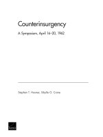
CY8C29/27/24/22xxx Counter Block Diagram, Data Path width n = 8, 16, 24 or 32
Functional Description
The Counter User Module employs from one to four digital PSoC blocks, each contributing 8 bits to the
total resolution. To form counters that exceed 8 bits, consecutive blocks are linked so their internal carry,
terminal count and compare signals are synchronously chained. This concatenates the 8-bit Count, Period
and Compare registers (data registers DR0, DR1 and DR2, respectively) from block to block to provide the
required resolution. In this way, Counters wider than 8 bits operate as a single monolithic synchronous
counter.
The Counter API provides functions that may be called from C and assembly to stop and start operation of
the Counter and to read and write the various data registers. The data register values may also be
established by using the Device Editor. Once started, the Count register is decremented on the rising edge
of each clock cycle at which the active-high enable input signal is asserted. On the rising clock edge
following the terminal count when the Count register reaches zero, it is reloaded from the Period register.
The Period register can be modified with a new value at anytime. When the Counter is stopped, writing a
value to the Period register also changes the value in the Count register. While the Counter is running,
writing the Period register does not update the Count register with the new Period value until the next
reload occurs, following terminal count. Because the terminal count is reached when the count is zero, the
period of operation and of the output signal is greater by 1 than the value stored in the Period register. The
duration in terms of the period of the input clock is given by the following equation.
OutputPeriod = ( PeriodValue + 1 )t CLK
Equation 1
The Counter asserts its output low when stopped. While running, a comparator controls the duty cycle of
the output signal. During every clock cycle, this comparator tests the values of the Count register against
that of the Compare register. The comparator performs a "less than" or "less than or equal" test depending
on an option selected using the Device Editor. The Counter asserts active-high truth value of the
comparison at the rising edge of the clock following the period in which the comparison is made. The ratio
between the compare value and the period sets the duty cycle of the output waveform. The duty cycle ratio
can be computed using the following equation.
CompareValue -----------------------------------------, For Less Than comparison
PeriodValue + 1
DutyCycle =
+ 1 CompareValue
-----------------------------------------------, For Less Than Or Equal To comparison
PeriodValue + 1
2
Equation 2
September 7, 2004
General Purpose Counters
The following table summarizes some special output signal conditions based on the setting of the Period
register, the Compare register, and the comparison operation.
Counter Special Output Signal Conditions
Period Register Value
Compare Type
Compare Register Value
Ratio of Pulse-Width High
Timer to period
0
Don’t Care
>0
1.0
0
≤
0
1.0
0
<
0
0.0
>0
≤
0
1/(Period+1)
>0
<
0
0.0
Period = Compare
≤
Period = Compare
1.0
Period = Compare
<
Period = Compare
Period/(Period+1)
Compare Value > Period
Don’t Care
Compare Value > Period
1.0
The value of the Compare register may be set using the Device Editor or during run time using the API. No
buffering of the Compare register is provided in the way the Period register buffers the Count register prior
to terminal count. Therefore, changes to the Compare register affect the compare output on the next clock
cycle, rather than following terminal count. This can produce periods with multiple pulses.
In the CY8C29/27/24/22xxx device families, the Counter User Module provides the terminal count signal
as an auxiliary output. This active-high signal is asserted on the rising edge of the clock cycle following
terminal count in which the count register is loaded from the Period register.
An interrupt can be programmed to occur on terminal count or when the compare becomes true. The
comparator output triggers an interrupt on the rising edge of the output signal and the terminal count
triggers an interrupt one-half clock cycle before the falling edge of the output signal. This option is set
using the Device Editor. Enabling or disabling the interrupt is done at run time using the Counter API.
Global interrupts must be enabled before the Counter’s interrupt will fire.
Care should be taken when modifying the Compare register since its value, in conjunction with the current
count value, determines the Counter’s output state. To prevent a possible premature low assertion of the
output signal and potential glitches, the Compare register should be modified after the terminal count
condition is detected using the interrupt.
For applications that require a faster duty cycle update interval, the output of the Counter can be routed to
a pin where its state is polled. Upon the detection of the output transition from high to low, the Compare
can then be updated. Note that if the Compare causes the compare true condition, then the output is
asserted high on the next clock.
Acquiring the Count register value should be done very carefully. Reading the Count register causes its
contents to latch into the Compare register. This causes the output duty cycle to change.
If you need to read the Count register “on-the-fly,” then the ReadCounter() API function can be called. This
function temporarily disables the clock, saves the Compare register contents, reads the Count register,
reads the Compare register, restores the Compare register, and then restores the clock. See the
description for the ReadCounter() function in the Application Programming Interface section for possible
side effects.
September 7, 2004
3
User Module Data Sheet
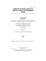
Timing
The Counter User Module’s operation may be gated on and off, or clocked by external pins routed to the
Counter by the global bus feature of the PSoC deviceThe following figure illustrates the timing for the
Counter User Module.
Clock
Period Reg
M
CompareValue Reg
N
Start Bit
Enable Signal
Counter Load of Period
Counter Reg
M
M-1
M-2
N+1
N
N-1
1
Compare
True
Output
0
M
M-1 M-2
Compare
False
N+1
N
N-1
1
0
M
M-1
Period = M+1
Duty Cycle = (N+1)/(M+1)
Terminal Count
Terminal Count
Counter Timing Diagram
AC Electrical Characteristics
Counter AC Electrical Characteristics
Parameter
Typical
Limit
Units
Maximum input frequency
--
481
Conditions and Notes
MHz
Vdd=5.0V2
Maximum output frequency
--
241
MHz
Vdd=5.0V and 48 MHz input clock
--
123
MHz
Vdd=3.3V and 24 MHz input clock
Electrical Characteristics Notes
1. If the input or output is routed through the global buses, then the frequency is limited to a maximum of 12 MHz.
2. Provided enable signal is always high; otherwise, the limit is 24MHz.
3. Fastest clock available to PSoC blocks is 24 MHz at 3.3V operation.
Placement
The Counter consumes one Digital PSoC block per 8 bits of resolution. When more than one block is
allocated, all will be placed consecutively by the Device Editor in order of increasing block number from
least-significant byte (LSB) to most significant (the MSB). Each block is given a symbolic name displayed
by the device editor during and after placement. The API qualifies all register names with user assigned
4
September 7, 2004
General Purpose Counters
instance name and block name to provide direct access to the Counter registers through the API include
files. The block names assigned by the various Counter User Modules are given in the following table.
Symbolic Names of the Mapped PSoC Blocks
PSoC Block
Number
8-Bit Counter
16-Bit Counter
24-Bit Counter
32-Bit Counter
1
CNTR8
CNTR16_LSB
CNTR24_LSB
CNTR32_LSB
2
–
CNTR16_MSB
CNTR24_ISB
CNTR32_ISB1
3
–
–
CNTR24_MSB
CNTR32_ISB2
4
–
–
–
CNTR32_MSB
Parameters and Resources
Once a Counter User Module has been selected and placed using the Device Editor, values may be
selected and altered for the following parameters.
Clock
The Clock parameter is selected from one of 15 sources. These sources include the 48 MHz oscillator
(5.0V operation only), lower frequencies (24V1 and 24V2) divided down from the 24 MHz system clock,
other PSoC blocks, and external inputs routed through global inputs and outputs.
Enable
The Enable parameter is selected from one of 16 sources. A high input enables continuous count, while a
low enable disables count without resetting the counter. The output is not affected by the state of the
enable input signal.
CompareOut
The compare output may be disabled (without interfering with interrupt operations) or connected to any of
the row output busses. It is always available as an input to the next higher digital PSoC block and to the
analog column clock selection multiplexors, regardless of the setting of this parameter. This parameter
appears only for members of the CY8C29/27/24/22xxx family of PSoC devices.
TerminalCountOut
The terminal count output is an auxiliary Counter output. This parameter allows it to be disabled or
connected to any of the row output busses. This parameter appears only for members of the CY8C29/27/
24/22xxx family of PSoC devices.
Period
This parameter sets the period of the counter. Allowed values are between 0 and 2n-1 where n is the width
of the counter in bits. The period is loaded into the Period register. The effective output waveform period of
Counter is the period count + 1. The value may be modified using the API.
Compare
This parameter sets the Compare register with the compare value. Allowed values are between zero and
the period value. The value may be modified using the API.
September 7, 2004
5
User Module Data Sheet
CompareType
This parameter sets the compare function type “less than” or “less than or equal” as described in the
functional description, above.
InterruptType
The Counter generates an interrupt on either the comparator true or on terminal count. A separate register
independently enables the interrupt.
ClockSync
In the PSoC devices, digital blocks may provide clock sources in addition to the system clocks. Digital
clock sources may even be chained in ripple fashion. This introduces skew with respect to the system
clocks. These skews are more critical in the CY8C29/27/24/22xxx PSoC device families because of
various data-path optimizations, particularly those applied to the system busses. This parameter may be
used to control clock skew and ensure proper operation when reading and writing PSoC block register
values. Appropriate values for this parameter should be determined from the following table.
ClockSync Value
Use
Sync to SysClk Use this setting for any 24 MHz (SysClk) derived clock source that is divided by two or more.
Examples include VC1, VC2, VC3 (when VC3 is driven by SysClk), 32KHz, and digital PSoC
blocks with SysClk-based sources. Externally generated clock sources should also use this
value to ensure that proper synchronization occurs.
Sync to SysClk*2 Use this setting for any 48 MHz (SysClk*2) based clock unless the resulting frequency is 48
MHz (in other words, when the product of all divisors is 1).
Use SysClk Direct Use when a 24 MHz (SysClk/1) clock is desired. This does not actually perform synchronization but provides low-skew access to the system clock itself. If selected, this option overrides
the setting of the Clock parameter, above. It should always be used instead of VC1, VC2,
VC3 or Digital Blocks where the net result of all dividers in combination produces a 24 Mhz
output.
Unsynchronized Use when the 48 MHz (SysClk*2) input is selected.
Use when unsynchronized inputs are desired. In general this use is advisable only when
interrupt generation is the sole application of the Counter.
InvertEnable
This parameter determines the sense of the enable input signal. When “Normal” is selected, the enable
input is active-high. Selecting “Invert” causes the sense to be interpreted as active-low.InvertEnable
applies only to the CY8C29/27/24/22xxx family of PSoC devices.
Interrupt Generation Control
The following two parameters InterruptAPI and IntDispatchMode are only accessible by setting the Enable
Interrupt Generation Control check box in PSoC Designer. This is available under Project >> Settings... >>
Device Editor.
InterruptAPI
The InterruptAPI parameter allows conditional generation of a User Module’s interrupt handler and
interrupt vector table entry. Select “Enable” to generate the interrupt handler and interrupt vector table
entry. Select “Disable” to bypass the generation of the interupt handler and interrupt vector table entry.
Properly selecting whether an Interrupt API is to be generated is recommended particularly with projects
that have multiple overlays where a single block resource is used by the different overlays. By selecting
6
September 7, 2004
General Purpose Counters
only Interrupt API generation when it is necessary the need to generate an interrupt dispatch code might
be eliminated, thereby reducing overhead.
IntDispatchMode
The IntDispatchMode parameter is used to specify how an interrupt request is handled for interrupts
shared by multiple user modules existing in the same block but in different overlays. Selecting
“ActiveStatus” causes firmware to test which overlay is active before servicing the shared interrupt
request. This test occurs every time the shared interrupt is requested. This adds latency and also
produces a nondeterministic procedure of servicing shared interrupt requests, but does not require any
RAM. Selecting “OffsetPreCalc” causes firmware to calculate the source of a shared interrupt request only
when an overlay is initially loaded. This calculation decreases interrupt latency and produces a
deterministic procedure for servicing shared interrupt requests, but at the expense of a byte of RAM.
Application Programming Interface
The Application Programming Interface (API) routines are provided as part of the user module to allow the
designer to deal with the module at a higher level. This sections specifies the interface to each function
together with related constants provided by the “include” files.
Note
In this, as in all user module APIs, the values of the A and X register may be altered by calling an
API function. It is the responsibility of the calling function to preserve the values of A and X prior to
the call if those values are required after the call. This “registers are volatile” policy was selected
for efficiency reasons and has been in force since version 1.0 of PSoC Designer. The C compiler
automatically takes care of this requirement. Assembly language programmers must ensure their
code observes the policy, too. Though some user module API function may leave A and X
unchanged, there is no guarantee they will do so in the future.
8-Bit Counter API
(CONSTANT) Counter8_PERIOD
Description:
Represents the value chosen for the Period field of the Counter8 in the Device Editor. The value can
have a range between 0 and 255.
(CONSTANT) Counter8_COMPARE_VALUE
Description:
Represents the value chose for the PulseWidth field of the Counter8 in the Device Editor. The value
can have a range between 0 and 255.
(FUNCTION) Counter8_EnableInt
Description:
Enables interrupt mode operation.
C Prototype:
void Counter8_EnableInt(void);
Assembly:
call Counter8_EnableInt
Parameters:
None
September 7, 2004
7
User Module Data Sheet
Return Value:
None
Side Effects:
The A and X registers may be modified by this or future implementations of this function. The same is
true for all RAM page pointer registers in the Large Memory Model (CY8C29xxx). When necessary, it
is the calling function's responsibility to preserve the values across calls to fastcall16 functions.
(FUNCTION) Counter8_DisableInt
Description:
Disables interrupt mode operation.
C Prototype:
void Counter8_DisableInt(void);
Assembly:
call Counter8_DisableInt
Parameters:
None
Return Value:
None
Side Effects:
The A and X registers may be modified by this or future implementations of this function. The same is
true for all RAM page pointer registers in the Large Memory Model (CY8C29xxx). When necessary, it
is the calling function's responsibility to preserve the values across calls to fastcall16 functions.
(FUNCTION) Counter8_Start
Description:
Starts the Counter8 User Module. If the enable input is high, the counter will begin to down count.
C Prototype:
void Counter8_Start(void);
Assembly:
call Counter8_Start
Parameters:
None
Return Value:
None
Side Effects:
The A and X registers may be modified by this or future implementations of this function. The same is
true for all RAM page pointer registers in the Large Memory Model (CY8C29xxx). When necessary, it
is the calling function's responsibility to preserve the values across calls to fastcall16 functions.
(FUNCTION) Counter8_Stop
Description:
Stops counter operation.
C Prototype:
void Counter8_Stop(void);
8
September 7, 2004
General Purpose Counters
Assembly:
call Counter8_Stop
Parameters:
None
Return Value:
None
Side Effects:
The output will be reset low and writing to the Period register will cause the Counter register to update
with the new period value. The A and X registers may be modified by this or future implementations of
this function. The same is true for all RAM page pointer registers in the Large Memory Model
(CY8C29xxx). When necessary, it is the calling function's responsibility to preserve the values across
calls to fastcall16 functions.
(FUNCTION) Counter8_WritePeriod
Description:
Writes the Period register with the period value. The period value will be transferred from the Period
register to the Counter register immediately, if the Counter8 is stopped or when the counter reaches
the zero count.
C Prototype:
void Counter8_WritePeriod(BYTE bPeriod);
Assembly:
mov
A, [bPeriod]
call Counter8_WritePeriod
Parameters:
Counter period value is a value from 0 to 255.
Return Value:
None
Side Effects:
The A and X registers may be modified by this or future implementations of this function. The same is
true for all RAM page pointer registers in the Large Memory Model (CY8C29xxx). When necessary, it
is the calling function's responsibility to preserve the values across calls to fastcall16 functions.
(FUNCTION) Counter8_WriteCompareValue
Description:
Writes the Compare register with the compare value.
C Prototype:
void Counter8_WriteCompareValue(BYTE bCompareValue);
Assembly:
mov
A, [bCompareValue]
call Counter8_WriteCompareValue
Parameters:
Compare value is the value from 0 to the period value.
Return Value:
None
Side Effects:
Writing the CompareValue register, while the counter is active, will change the duty cycle of the output.
September 7, 2004
9
User Module Data Sheet
This may cause the output to glitch or change inadvertently. The A and X registers may be modified by
this or future implementations of this function. The same is true for all RAM page pointer registers in
the Large Memory Model (CY8C29xxx). When necessary, it is the calling function's responsibility to
preserve the values across calls to fastcall16 functions.
(FUNCTION) Counter8_bReadCompareValue
Description:
Reads the CompareValue register.
C Prototype:
BYTE Counter8_bReadCompareValue(void);
Assembly:
call Counter8_bReadCompareValue
mov
[bCompareValue], A
; store the value in RAM (if desired)
Parameters:
None
Return Value:
Compare value is stored in the CompareValue register and returned in the Accumulator.
Side Effects:
The A and X registers may be modified by this or future implementations of this function. The same is
true for all RAM page pointer registers in the Large Memory Model (CY8C29xxx). When necessary, it
is the calling function's responsibility to preserve the values across calls to fastcall16 functions.
Deprecated Aliases:
bCounter8_ReadCompareValue–This name may be withdrawn in future versions of PSoC Designer.
(FUNCTION) Counter8_bReadCounter
Description:
Reads the Count register value (hardware DR0 registers) while preserving the Compare register. This
function may be called to read the Count register while the counter is running or when it is stopped.
Inadvertant interrupts are prevented even though the Compare and Count registers briefly become
equal. However, there are important side effects (see below).
C Prototype:
BYTE Counter8_bReadCounter(void);
Assembly:
call Counter8_bReadCounter
mov
[bCounter], A
Parameters:
None
Returns:
Counter register value that is returned in the Accumulator.
Side Effects:
If the Counter user module is enabled and counting at the time this function is called, some clocks may
be ignored (and corresponding decrements of the Count register missed) because the user module
must be stopped momentarily. The A and X registers may be modified by this or future implementations of this function. The same is true for all RAM page pointer registers in the Large Memory Model
(CY8C29xxx). When necessary, it is the calling function's responsibility to preserve the values across
calls to fastcall16 functions.
10
September 7, 2004
General Purpose Counters
Deprecated Aliases:
bCounter8_ReadCounter–This name may be withdrawn in future versions of PSoC Designer.
16-Bit Counter
Application Programming Interface (API) routines are provided as part of the user module to allow the
designer to deal with the module at a higher level. The following are the API programming routines
provided for Counter16:
(CONSTANT) Counter16_PERIOD
Description:
Represents the value chosen for the Period field of the Counter16 in the Device Editor. The value can
have a range between 0 and 65535.
(CONSTANT) Counter16_COMPARE_VALUE
Description:
Represents the value chose for the PulseWidth field of the Counter16 in the Device Editor. The value
can have a range between 0 and 65535.
(FUNCTION) Counter16_EnableInt
Description:
Enables interrupt mode operation.
C Prototype:
void Counter16_EnableInt(void);
Assembly:
call Counter16_EnableInt
Parameters:
None
Return Value:
None
Side Effects:
The A and X registers may be modified by this or future implementations of this function. The same is
true for all RAM page pointer registers in the Large Memory Model (CY8C29xxx). When necessary, it
is the calling function's responsibility to preserve the values across calls to fastcall16 functions.
(FUNCTION) Counter16_DisableInt
Description:
Disables interrupt mode operation.
C Prototype:
void Counter16_DisableInt(void);
Assembly:
call Counter16_DisableInt
Parameters:
None
Return Value:
None
September 7, 2004
11
User Module Data Sheet
Side Effects:
The A and X registers may be modified by this or future implementations of this function. The same is
true for all RAM page pointer registers in the Large Memory Model (CY8C29xxx). When necessary, it
is the calling function's responsibility to preserve the values across calls to fastcall16 functions.
(FUNCTION) Counter16_Start
Description:
Starts the Counter16 User Module. If the enable input is high, the counter will begin to down count.
C Prototype:
void Counter16_Start(void);
Assembly:
call Counter16_Start
Parameters:
None
Return Value:
None
Side Effects:
The A and X registers may be modified by this or future implementations of this function. The same is
true for all RAM page pointer registers in the Large Memory Model (CY8C29xxx). When necessary, it
is the calling function's responsibility to preserve the values across calls to fastcall16 functions.
(FUNCTION) Counter16_Stop
Description:
Stops counter operation.
C Prototype:
void Counter16_Stop(void);
Assembly:
call Counter16_Stop
Parameters:
None
Return Value:
None
Side Effects:
The output will be reset low and writing to the Period register will cause the Counter register to update
with the new period value. The A and X registers may be modified by this or future implementations of
this function. The same is true for all RAM page pointer registers in the Large Memory Model
(CY8C29xxx). When necessary, it is the calling function's responsibility to preserve the values across
calls to fastcall16 functions.
(FUNCTION) Counter16_WritePeriod
Description:
Writes the Period register with the period value. The period value will be transferred from the Period
register to the Counter register immediately, if the Counter16 is stopped or when the counter reaches
the zero count.
C Prototype:
void Counter16_WritePeriod(WORD wPeriod);
12
September 7, 2004
General Purpose Counters
Assembly:
mov
X, [wPeriod]
;load the MSB, e.g. from RAM
mov
A, [wPeriod+1]
;load the LSB
call Counter16_WritePeriod
Parameters:
wPeriod: wPeriod is a value from 0 to 65535. The MSB is passed in the X register and the LSB in the
A register.
Return Value:
None
Side Effects:
The A and X registers may be modified by this or future implementations of this function. The same is
true for all RAM page pointer registers in the Large Memory Model (CY8C29xxx). When necessary, it
is the calling function's responsibility to preserve the values across calls to fastcall16 functions.
(FUNCTION) Counter16_WriteCompareValue
Description:
Writes the CompareValue register with the compare value.
C Prototype:
void Counter16_WriteCompareValue(WORD wCompareValue);
Assembly:
mov
X, [wCompareValue]
mov
A, [wCompareValue+1]
call Counter16_WriteCompareValue
Parameters:
wCompareValue: wCompareValue is a value from zero to the period value. The MSB is passed in the
X register and the LSB in the A register.
Return Value:
None
Side Effects:
Writing the CompareValue register while the counter is active will change the duty cycle of the output.
This may cause the output to glitch or change inadvertently. The A and X registers may be modified by
this or future implementations of this function. The same is true for all RAM page pointer registers in
the Large Memory Model (CY8C29xxx). When necessary, it is the calling function's responsibility to
preserve the values across calls to fastcall16 functions.
(FUNCTION) Counter16_wReadCompareValue
Description:
Reads the CompareValue register.
C Prototype:
WORD Counter16_wReadCompareValue(void);
Assembly:
call Counter16_wReadCompareValue
mov
[wCompareValue], X
mov
[wCompareValue+1], A
Parameters:
wReadCompareValue: Returns the 16-bit value obtained from the Compare register. The MSB is
passed in the X register and the LSB in the A register.
September 7, 2004
13
User Module Data Sheet
Return Value:
None
Side Effects:
The A and X registers may be modified by this or future implementations of this function. The same is
true for all RAM page pointer registers in the Large Memory Model (CY8C29xxx). When necessary, it
is the calling function's responsibility to preserve the values across calls to fastcall16 functions.
Deprecated Aliases:
wCounter16_ReadCompareValue–This name may be withdrawn in future versions of PSoC Designer.
(FUNCTION) Counter16_wReadCounter
Description:
Reads the Count register value (hardware DR0 registers) while preserving the Compare register. This
function may be called to read the Count register while the counter is running or when it is stopped.
Inadvertant interrupts are prevented even though the Compare and Count registers briefly become
equal. However, there are important side effects (see below).
C Prototype:
WORD Counter16_wReadCounter(void);
Assembly:
call Counter16_wReadCounter
mov
[wCount], X
mov
[wCount+1], A
Parameters:
None
Returns:
wReadCounter: wReadCounter value in the Count register. The MSB is passed in the X register and
the LSB in the A register.
Side Effects:
If the Counter user module is enabled and counting at the time this function is called, some clocks may
be ignored (and corresponding decrements of the Count register missed) because the user module
must be stopped momentarily. The A and X registers may be modified by this or future implementations of this function. The same is true for all RAM page pointer registers in the Large Memory Model
(CY8C29xxx). When necessary, it is the calling function's responsibility to preserve the values across
calls to fastcall16 functions.
Deprecated Aliases:
wCounter16_ReadCounter–This name may be withdrawn in future versions of PSoC Designer.
24-Bit Counter API
Application Programming Interface (API) routines are provided as part of the user module to allow the
designer to deal with the module at a higher level. The following are the API programming routines
provided for Counter24.
(CONSTANT) Counter24_PERIOD
Description:
Represents the value chosen for the Period field of the Counter24 in the Device Editor. The value can
have a range between 0 and 16777215.
14
September 7, 2004
General Purpose Counters
(CONSTANT) Counter24_COMPARE_VALUE
Description:
Represents the value chose for the PulseWidth field of the Counter24 in the Device Editor. The value
can have a range between 0 and 16777215.
(FUNCTION) Counter24_EnableInt
Description:
Enables interrupt mode operation.
C Prototype:
void Counter24_EnableInt(void);
Assembly:
call Counter24_EnableInt
Parameters:
None
Return Value:
None
Side Effects:
The A and X registers may be modified by this or future implementations of this function. The same is
true for all RAM page pointer registers in the Large Memory Model (CY8C29xxx). When necessary, it
is the calling function's responsibility to preserve the values across calls to fastcall16 functions.
(FUNCTION) Counter24_DisableInt
Description:
Disables interrupt mode operation.
C Prototype:
void Counter24_DisableInt(void);
Assembly:
call Counter24_DisableInt
Parameters:
None
Return Value:
None
Side Effects:
The A and X registers may be modified by this or future implementations of this function. The same is
true for all RAM page pointer registers in the Large Memory Model (CY8C29xxx). When necessary, it
is the calling function's responsibility to preserve the values across calls to fastcall16 functions.
(FUNCTION) Counter24_Start
Description:
Starts the Counter24 User Module. If the enable input is high, the counter will begin to down count.
C Prototype:
void Counter24_Start(void);
Assembly:
call Counter24_Start
September 7, 2004
15
User Module Data Sheet
Parameters:
None
Return Value:
None
Side Effects:
The A and X registers may be modified by this or future implementations of this function. The same is
true for all RAM page pointer registers in the Large Memory Model (CY8C29xxx). When necessary, it
is the calling function's responsibility to preserve the values across calls to fastcall16 functions.
(FUNCTION) Counter24_Stop
Description:
Stops counter operation.
C Prototype:
void Counter24_Stop(void);
Assembly:
call Counter24_Stop
Parameters:
None
Return Value:
None
Side Effects:
The output will be reset low and writing to the Period register will cause the Counter register to update
with the new period value. The A and X registers may be modified by this or future implementations of
this function. The same is true for all RAM page pointer registers in the Large Memory Model
(CY8C29xxx). When necessary, it is the calling function's responsibility to preserve the values across
calls to fastcall16 functions.
(FUNCTION) Counter24_WritePeriod
Description:
Writes the Period register with the period value. The period value will be transferred from the Period
register to the Counter register immediately, if the Counter24 is stopped or when the counter reaches
the zero count.
C Prototype:
void Counter24_WritePeriod(DWORD dwPeriod);
Assembly:
mov
X, dwPeriod
call Counter24_WritePeriod
Parameters:
dwPeriod: dwPeriod is a value from 0 to 224-1. The X register is loaded with the address of the MSB of
dwPeriod.
Return Value:
None
Side Effects:
The A and X registers may be modified by this or future implementations of this function. The same is
true for all RAM page pointer registers in the Large Memory Model (CY8C29xxx). When necessary, it
is the calling function's responsibility to preserve the values across calls to fastcall16 functions.
16
September 7, 2004
General Purpose Counters
(FUNCTION) Counter24_WriteCompareValue
Description:
Writes the CompareValue register with the compare value.
C Prototype:
void Counter24_WriteCompareValue(DWORD dwCompareValue);
Assembly:
mov
X, dwCompareValue
call Counter24_WriteCompareValue
Parameters:
dwCompareValue: dwCompareValue is a value from 0 to the period value. The X register is loaded
with the address of the MSB of dwCompareValue.
Return Value:
None
Side Effects:
Writing the CompareValue register, while the counter is active, will change the duty cycle of the output.
This may cause the output to glitch or change inadvertently. The A and X registers may be modified by
this or future implementations of this function. The same is true for all RAM page pointer registers in
the Large Memory Model (CY8C29xxx). When necessary, it is the calling function's responsibility to
preserve the values across calls to fastcall16 functions.
(FUNCTION) Counter24_ReadCompareValue
Description:
Reads the CompareValue register.
C Prototype:
void Counter24_ReadCompareValue(DWORD * pdwCompareValue);
Assembly:
mov
X, pdwCompareValue
; X points to the DWORD
call Counter24_ReadCompareValue
Parameters:
pdwCompareValue: pdwCompareValue is the pointer to a DWORD to hold the CompareValue register
data. The X register is loaded with the address of the DWORD.
Return Value:
CompareValue is returned in specified buffer.
Side Effects:
The A and X registers may be modified by this or future implementations of this function. The same is
true for all RAM page pointer registers in the Large Memory Model (CY8C29xxx). When necessary, it
is the calling function's responsibility to preserve the values across calls to fastcall16 functions. Currently, only the IDX_PP page pointer register is modified.
(FUNCTION) Counter24_ReadCounter
Description:
Reads the Count register value (hardware DR0 registers) while preserving the Compare register. This
function may be called to read the Count register while the counter is running or when it is stopped.
Inadvertant interrupts are prevented even though the Compare and Count registers briefly become
equal. However, there are important side effects (see below).
September 7, 2004
17
User Module Data Sheet
C Prototype:
void Counter24_ReadCounter(DWORD * pdwCount);
Assembly:
mov
X, pdwCount
; X points to the return buffer
call Counter24_ReadCounter
Parameters:
pdwCount: pdwCount is the pointer to a DWORD to hold the Count register data. The X register is
loaded with the address of the DWORD.
Return Value:
Count value is returned in a specified buffer.
Side Effects:
If the Counter user module is enabled and counting at the time this function is called, some clocks may
be ignored (and corresponding decrements of the Count register missed) because the user module
must be stopped momentarily. The A and X registers may be modified by this or future implementations of this function. The same is true for all RAM page pointer registers in the Large Memory Model
(CY8C29xxx). When necessary, it is the calling function's responsibility to preserve the values across
calls to fastcall16 functions. Currently, only the IDX_PP page pointer register is modified.
32-bit Counter API
Application Programming Interface (API) routines are provided as part of the user module to allow the
designer to deal with the module at a higher level. The following are the API programming routines
provided for Counter32.
(CONSTANT) Counter8_PERIOD
Description:
Represents the value chosen for the Period field of the Counter32 in the Device Editor. The value can
have a range between 0 and 4294967295.
(CONSTANT) Counter8_COMPARE_VALUE
Description:
Represents the value chose for the PulseWidth field of the Counter32 in the Device Editor. The value
can have a range between 0 and 4294967295.
(FUNCTION) Counter32_EnableInt
Description:
Enables interrupt mode operation.
C Prototype:
void Counter32_EnableInt(void);
Assembly:
call Counter32_EnableInt
Parameters:
None
Return Value:
None
Side Effects:
The A and X registers may be modified by this or future implementations of this function. The same is
18
September 7, 2004
General Purpose Counters
true for all RAM page pointer registers in the Large Memory Model (CY8C29xxx). When necessary, it
is the calling function's responsibility to preserve the values across calls to fastcall16 functions.
(FUNCTION) Counter32_DisableInt
Description:
Disables interrupt mode operation.
C Prototype:
void Counter32_DisableInt(void);
Assembly:
call Counter32_DisableInt
Parameters:
None
Return Value:
None
Side Effects:
The A and X registers may be modified by this or future implementations of this function. The same is
true for all RAM page pointer registers in the Large Memory Model (CY8C29xxx). When necessary, it
is the calling function's responsibility to preserve the values across calls to fastcall16 functions.
(FUNCTION) Counter32_Start
Description:
Starts the Counter32 User Module. If the enable input is high, the counter will begin to down count.
C Prototype:
void Counter32_Start(void);
Assembly:
call Counter32_Start
Parameters:
None
Return Value:
None
Side Effects:
The A and X registers may be modified by this or future implementations of this function. The same is
true for all RAM page pointer registers in the Large Memory Model (CY8C29xxx). When necessary, it
is the calling function's responsibility to preserve the values across calls to fastcall16 functions.
(FUNCTION) Counter32_Stop
Description:
Stops counter operation.
C Prototype:
void Counter32_Stop(void);
Assembly:
call Counter32_Stop
Parameters:
None
September 7, 2004
19
User Module Data Sheet
Return Value:
None
Side Effects:
The output will be reset low and writing to the Period register will cause the Counter register to also
update with the new period value. The A and X registers may be modified by this or future implementations of this function. The same is true for all RAM page pointer registers in the Large Memory Model
(CY8C29xxx). When necessary, it is the calling function's responsibility to preserve the values across
calls to fastcall16 functions.
(FUNCTION) Counter32_WritePeriod
Description:
Writes the Period register with the period value. The period value will be transferred from the Period
register to the Counter register immediately, if the Counter32 is stopped or when the counter reaches
the zero count.
C Prototype:
void Counter32_WritePeriod(DWORD dwPeriod);
Assembly:
mov
X, dwPeriod
call Counter32_WritePeriod
Parameters:
dwPeriod: Provides a value from 0 to 232-1. The X register is loaded with the address of the MSB of
dwPeriod.
Return Value:
None
Side Effects:
The A and X registers may be modified by this or future implementations of this function. The same is
true for all RAM page pointer registers in the Large Memory Model (CY8C29xxx). When necessary, it
is the calling function's responsibility to preserve the values across calls to fastcall16 functions.
(FUNCTION) Counter32_WriteCompareValue
Description:
Writes the CompareValue register with the compare value.
C Prototype:
void Counter32_WriteCompareValue(DWORD dwCompareValue);
Assembly:
mov
X, dwCompareValue
call Counter32_WriteCompareValue
Parameters:
dwCompareValue: Value from 0 to the period value.The X register is loaded with the address of the
MSB of dwCompareValue.
Return Value:
None
Side Effects:
Writing the CompareValue register, while the counter is active, will change the duty cycle of the output.
This may cause the output to glitch or change inadvertently. The A and X registers may be modified by
this or future implementations of this function. The same is true for all RAM page pointer registers in
20
September 7, 2004
General Purpose Counters
the Large Memory Model (CY8C29xxx). When necessary, it is the calling function's responsibility to
preserve the values across calls to fastcall16 functions.
(FUNCTION) Counter32_ReadCompareValue
Description:
Reads the CompareValue register.
C Prototype:
void Counter32_ReadCompareValue(DWORD * pdwCompareValue);
Assembly:
mov
X, pdwCompareValue
; X points to the return buffer
call Counter32_ReadCompareValue
Parameters:
pdwCompareValue: Pointer to a DWORD to hold the CompareValue register data. The X register is
loaded with the address of the MSB of pdwCompareValue.
Return Value:
CompareValue is returned in the specified buffer.
Side Effects:
The A and X registers may be modified by this or future implementations of this function. The same is
true for all RAM page pointer registers in the Large Memory Model (CY8C29xxx). When necessary, it
is the calling function's responsibility to preserve the values across calls to fastcall16 functions. Currently, only the IDX_PP page pointer register is modified.
(FUNCTION) Counter32_ReadCounter
Description:
Reads the Count register value (hardware DR0 registers) while preserving the Compare register. This
function may be called to read the Count register while the counter is running or when it is stopped.
Inadvertant interrupts are prevented even though the Compare and Count registers briefly become
equal. However, there are important side effects (see below).
C Prototype:
void Counter32_ReadCounter(DWORD * pdwCount);
Assembly:
mov
X, pdwCount
; X points to the return buffer
call Counter32_ReadCounter
Parameters:
pdwCount: Pointer to a DWORD to hold the Counter register data. The X register is loaded with the
address of the MSB of pdwCount.
Return Value:
Count value is returned in the specified buffer.
Side Effects:
If the Counter user module is enabled and counting at the time this function is called, some clocks may
be ignored (and corresponding decrements of the Count register missed) because the user module
must be stopped momentarily. The A and X registers may be modified by this or future implementations of this function. The same is true for all RAM page pointer registers in the Large Memory Model
(CY8C29xxx). When necessary, it is the calling function's responsibility to preserve the values across
calls to fastcall16 functions. Currently, only the IDX_PP page pointer register is modified.
September 7, 2004
21
User Module Data Sheet
Sample Code
8-Bit Counter Sample Firmware Source Code
In the following examples, the correspondence between the C and assembly code is simple and direct.
The values shown for the period and compare value are each “off-by-1” from the cardinal values because
the registers are zero-based; that is, zero is the terminal count in their down-count cycle. Passing a simple
one byte parameter in the A register rather than on the stack is a performance optimization used by both
the assembler and C compiler for user module APIs. The C compiler employs this mechanism for “INT”
types instead of pushing the argument on the stack when it sees the #pragma fastcall declarations in the
Counter8.h file.
The following source illustrates the use of the APIs in assembly language.
;;;;;;;;;;;;;;;;;;;;;;;;;;;;;;;;;;;;;;;;;;;;;;;;;;;;;;;;;;;;;;;;;;;;;;;;;
; Description:
;
This sample shows how to create a clock divider. This specific
;
example divides the clock by 8.
;;;;;;;;;;;;;;;;;;;;;;;;;;;;;;;;;;;;;;;;;;;;;;;;;;;;;;;;;;;;;;;;;;;;;;;;;
include "Counter8.inc"
DivideClockByEight:
mov
A, 07h
call Counter8_WritePeriod
mov
A, 03h
call Counter8_WriteCompareValue
call Counter8_EnableInt
M8C_EnableGInt
call Counter8_Start
; include the Counter8 interface
; set the period to 8
; generate a 50% duty cycle
; enable the Counter Interrupt
; enable global interrupts
; start to count when the enable
;
input is asserted
The same code in C is as follows.
/************************************************************************
* Description:
*
This sample shows how to create a clock divider. This specific
*
example divides the clock by 8.
************************************************************************/
#include "Counter8.h"
Counter8_WritePeriod(0x07);
Counter8_WriteCompareValue(0x03);
Counter8_EnableInt();
M8C_EnableGInt;
Counter8_Start();
/*
/*
/*
/*
/*
set period to eight clocks
generate a 50% duty cycle
ensure interrupt is enabled
enable global interrupts
start the counter!
*/
*/
*/
*/
*/
In the two cases above, the only required include file is Counter8.h which provides the necessary
declarations (pragmas and prototypes). Both assembly and C include files provide symbolic names for use
when direct register access is required by an application. In CY8C29/27/24/22xxx user modules, the
include files also provide macro definitions for in-line expansion of the source code of some of the shorter
API functions. The files PSoCAPI.inc and PSoCAPI.h may be used instead of Counter8.inc and
Counter8.h, respectively. These files contain include statements for each of the user modules instantiated
(and placed) in a PSoC Designer project.
22
September 7, 2004
General Purpose Counters
16-Bit Counter Sample Firmware Source Code
In the following examples, the correspondence between the C and assembly code is relatively simple.
Passing a simple two byte “INT” parameter with the LSB in the A register and the MSB in the X register is
a performance optimization used by both the assembler and C compiler for user module APIs. The C
compiler employs this mechanism for “INT” types instead of pushing the argument on the stack when it
sees the #pragma fastcall declarations in the Counter16.h file.
The following source illustrates the use of the APIs in assembly language.
;;;;;;;;;;;;;;;;;;;;;;;;;;;;;;;;;;;;;;;;;;;;;;;;;;;;;;;;;;;;;;;;;;;;;;;;;
; Description:
;
This sample shows how to create a clock divider. This specific
;
example divides the clock by 1000.
;;;;;;;;;;;;;;;;;;;;;;;;;;;;;;;;;;;;;;;;;;;;;;;;;;;;;;;;;;;;;;;;;;;;;;;;;
include "Counter16.inc"
; include the Counter16 interface
mov
mov
call
X, 03h
A, E7h
Counter16_WritePeriod
; set the period to 1000
;
i.e., 1000-1 = 999 = 0x03e7
mov
mov
call
X, 01h
A, F3h
Counter16_WriteCompareValue
; Generate a 50% duty cycle
;
i.e., 500-1 = 499 = 0x01F3
call Counter16_EnableInt
M8C_EnableGInt
call Counter16_Start
; enable the Counter Interrupt
; enable global interrupts
; start to count when the enable
;
input is asserted
The same code in C is as follows.
/************************************************************************
* Description:
*
This sample shows how to create a clock divider. This specific
*
example divides the clock by 1000.
************************************************************************/
#include "Counter16.h"
{
}
Counter16_WritePeriod(999);
Counter16_WriteCompareValue(499);
Counter16_EnableInt();
M8C_EnableGInt;
Counter16_Start();
/*
/*
/*
/*
/*
set the period to 1000
generate a 50 duty cycle
disable the interrupt
enable global interrupts
start the counter
*/
*/
*/
*/
*/
In the two cases above, the only required include file is Counter16.h which provides the necessary
declarations (pragmas and prototypes). Both assembly and C include files provide symbolic names for use
when direct register access is required by an application. In CY8C29/27/24/22xxx user modules, the
include files also provide macro definitions for in-line expansion of the source code of some of the shorter
API functions. The files PSoCAPI.inc and PSoCAPI.h may be used instead of Counter16.inc and
Counter16.h, respectively. These files contain include statements for each of the user modules
instantiated (and placed) in a PSoC Designer project.
September 7, 2004
23
User Module Data Sheet
24-Bit Counter Sample Firmware Source Code
The following assembly language source illustrates the use of the APIs.
;;;;;;;;;;;;;;;;;;;;;;;;;;;;;;;;;;;;;;;;;;;;;;;;;;;;;;;;;;;;;;;;;;;;;;;;;
; Description:
;
This sample creates a 10 Hz output with a 50% duty cycle and
;
interrupts that occur on reaching terminal count
;
;
Counter24 user module must be configured with a 24 MHz input clock.
;;;;;;;;;;;;;;;;;;;;;;;;;;;;;;;;;;;;;;;;;;;;;;;;;;;;;;;;;;;;;;;;;;;;;;;;;
include "m8c.inc"
include "Counter24.inc"
STACKFRAME_SIZE:
equ
; include the device interface
; include the Counter24 interface
4
; Size of a DWORD in bytes
mov
add
X, SP
SP, STACKFRAME_SIZE
; create a stack frame pointer
;
and allocate space for a DWORD
mov
mov
mov
mov
push
call
pop
[X+0], 0
[X+1], 24h
[X+2], 9eh
[X+3], ffh
X
Counter24_WritePeriod
X
;
;
;
;
;
;
;
mov
mov
mov
mov
call
[X+0], 0
[X+1], 12h
[X+2], 4fh
[X+3], 7fh
Counter24_WriteCompareValue
; load the Compare val on the stack
;
= (2,400,000–1)/2 = 0x00124f7f
;
...
;
...
; write the Compare register
; (no need to preserve X this time)
add
SP, -STACKFRAME_SIZE
call Counter24_EnableInt
M8C_EnableGInt
call Counter24_Start
;
;
;
;
;
load the Period onto the stack
= 2,400,000 –1 = 0x00249eff
...
...
preserve frame ptr across the call
set the Period register
restore frame pointer
deallocate the stack frame
enable the interrupts mask
enable the global interrupts
start to count when the enable
input is asserted
The equivalent code in C is as follows.
/* include the Counter24 API header file */
#include "Counter24.h"
#include "m8c.h"
Counter24_WritePeriod(2400000-1);
Counter24_WriteCompareValue((2400000-1)/2);
Counter24_EnableInt();
M8C_EnableGInt;
Counter24_Start();
24
September 7, 2004
General Purpose Counters
32-Bit Counter Sample Firmware Source Code
The following assembly language source illustrates the use of the Counter32 APIs.
;;;;;;;;;;;;;;;;;;;;;;;;;;;;;;;;;;;;;;;;;;;;;;;;;;;;;;;;;;;;;;;;;;;;;;;;;
; Description:
;
This sample shows how to create a 1 Hz interrupt and 1Hz output
;
with a 50% duty cycle. A Counter32 User Module must have been
;
configured with a 24 MHz input clock. Interrupts may be configured
;
either for triggering on the terminal count or compare true
;;;;;;;;;;;;;;;;;;;;;;;;;;;;;;;;;;;;;;;;;;;;;;;;;;;;;;;;;;;;;;;;;;;;;;;;;
include "m8c.inc"
include "Counter32.inc"
STACKFRAME_SIZE:
equ 4
Counter32:
mov
X, SP
add
SP, STACKFRAME_SIZE
; Nbr bytes for a 32-bit parameter
; create a stack frame pointer
;
and allocate space for a DWORD
mov
mov
mov
mov
push
call
pop
[X+0], 01h
[X+1], 6eh
[X+2], 35h
[X+3], ffh
X
Counter32_WritePeriod
X
;
;
;
;
;
;
;
mov
mov
mov
mov
call
[X+0], 00h
[X+1], b7h
[X+2], 1ah
[X+3], ffh
Counter32_WriteCompareValue
; load the Compare Value on the stack
;
= (24,000,000–1)/2 = 0x00b71aff
;
...
;
and ...
; Update the Compare register
; (no need to preserve X this time)
add
SP, -STACKFRAME_SIZE
call Counter32_EnableInt
M8C_EnableGInt
call Counter32_Start
;
;
;
;
;
load the Period onto the stack
= 24,000,000 –1 = 0x16e35ff
...
and...
preserve frame ptr across the call
Update the Period register
restore frame pointer
deallocate the stack frame
enable Counter interrupts
enable global interrupts
start to count when the enable
input is asserted
The same code in C is as follows.
#include "Counter32.h"
#include "m8c.h"
/* Create a 1 Hz square wave */
Counter32_WritePeriod(24000000-1);
/* set the period
*/
Counter32_WriteCompareValue((24000000-1)/2);
/* set the duty cycle*/
Counter32_EnableInt();
/* enable Counter interrupts */
M8C_EnableGInt;
/* enable global interrupts
*/
Counter32_Start();
/* start the counter!
*/
September 7, 2004
25