Lecture03 networking
Bạn đang xem bản rút gọn của tài liệu. Xem và tải ngay bản đầy đủ của tài liệu tại đây (1.13 MB, 23 trang )
2/17/2016
IT4371: Distributed Systems
Spring 2016
Networking
Dr. Nguyen Binh Minh
Department of Information Systems
School of Information and Communication Technology
Hanoi University of Science and Technology
Today…
Last Session:
Architectural Models of Distributed Systems
Today’s Session:
Network Types
Networking Principles: Layering, Encapsulation, Routing and Congestion
Control
Scalability, Reliability and Fault-tolerance in the Internet
1
2/17/2016
Introduction to Networking – Learning Objectives
You will identify how computers over Internet communicate
Specifically, after today’s class you will be able to:
Identify different types of networks
Describe networking principles such as layering, encapsulation
and packet-switching
Examine how packets are routed and how congestion is controlled
Analyze scalability, reliability and fault-tolerance over Internet
Networks in Distributed Systems
Distributed System is simply a collection of components that communicate to
solve a problem
Why should distributed systems programmers know about networks?
Networking issues severely affect performance, fault-tolerance and security of Distributed
Systems
e.g., Gmail outage on Sep 1, 2010 – Google Spokesman said “we had slightly
underestimated the load which some recent changes placed on the request routers. … .
few of the request routers became overloaded… causing a few more of them to also
become overloaded, and within minutes nearly all of the request routers were
overloaded.”
2
2/17/2016
Network Classification
Important ways to classify networks
1.
Based on size
Body Area Networks (BAN)
Personal Area Networks (PAN)
Local Area Networks (LAN)
Wide Area Networks (WAN)
2.
Based on technology
Ethernet Networks
Wireless Networks
Cellular Networks
Network classification – BANs and PANs
Body Area Networks (BAN):
Devices form wearable computing units
Several Body Sensor Units (BSUs)
communicate with Body Central Unit (BCU)
Typically, low-cost and low-energy networking
Personal Area Networks (PAN):
PAN connects various digital devices carried by a user (mobile
phones, tablets, cameras)
Low-cost and low-energy networking
e.g., Bluetooth
3
2/17/2016
Network Classification – LAN
Computers connected by single communication medium
e.g., twisted copper wire, optical fiber
High data-transfer-rate and low latency
LAN consists of
1. Segment
Usually within a department/floor of a building
Shared bandwidth, no routing necessary
2. Local Networks
Serves campus/office building
Many segments connected by a switch/hub
Typically, represents a network within an organization
Network classification – WAN
Generally covers a wider area (cities, countries,...)
Consists of networks of different organizations
Traffic is routed from one organization to another
Routers
Bandwidth and delay
Varies
Worse than a LAN
Largest WAN = Internet
4
2/17/2016
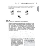
Brief Summary of Important
Networks (Based on Size)
A Segment
A Network
Types of Networks – Based on Technology
Ethernet Networks
Predominantly used in the wired Internet
Wireless LANs
Primarily designed to provide
wireless access to the Internet
Low-range, High-bandwidth
Cellular networks (2G/3G)
Initially, designed to carry voice
Large range (few kms)
Low-bandwidth
5
2/17/2016
Typical Performance for Different Types of Networks
Network
Example
Range
Bandwidth
(Mbps)
Latency (ms)
Wired LAN
Ethernet
1-2 km
10 – 10,000
1 – 10
Wired WAN
Internet
Worldwide
0.5 – 600
100 – 500
Wireless PAN
Bluetooth
10 – 30 m
0.5 – 2
5 – 20
Wireless LAN
WiFi
0.15 – 1.5 km
11 – 108
5 – 20
Cellular
2G – GSM
100m – 20 km
0.270 – 1.5
5
Modern Cellular
3G
1 – 5 km
348 – 14.4
100 – 500
Networking Principles
Network Protocols
Packet transmission
Network Layers
Physical layer
Data-link layer
Network layer and routing
Transport layer and congestion control
6
2/17/2016
Network Protocols
If two entities want to communicate on a network, pre-defined agreements are
necessary
How many bits should be used to signal a 0-bit or a 1-bit?
How does the receiver know the last bit in the message?
How can a receiver detect if the message is damaged?
Protocol is a well-known set of rules and formats to be used for communication
between the entities
Standardizing a well-known set of protocols supports communication among
heterogeneous entities
Packet Transmission
Messages are broken up into packets
A packet is the unit of data that is transmitted
between an origin and a destination
Packets can be of arbitrary lengths
Maximum size of the packet is known as Maximum Transmission Unit (MTU)
MTU prevents one host from sending a very long message
Each packet has two main fields
Header: Contains meta-information about the packet
e.g., Length of the packet, receiver ID
Data
Header
Data
7
2/17/2016
Network Layers
Network software is arranged into a hierarchy of layers
Protocols in one layer perform one specific functionality
Layering is a scalable and modular design for a complex software
Typical functionalities in a network software:
Functionality
011100011
0011 011
Layer
Transmit bits over a transmission medium
Physical
Coordinate transmissions from multiple hosts that
are directly connected over a common medium
Data link
Route the packet through intermediate networks
Network
Handle messages – rather than packets –
between sender and receiver processes
Transport
Satisfy communication requirements for
specific applications
Src
Dest
Destination machine
Application
P1
P2
P3
OSI Reference Model
Open Systems Interconnection (OSI) Reference Model
A layered networking model standardized by ISO
The model identifies various layers and their functionalities
Functionality
Layer
Example Protocols
Satisfy communication requirements for specific applications
Application
HTTP, FTP
Transmit data in network representation that is independent of
representation in individual computers
Presentation
CORBA data
representation
Support reliability and adaptation, such as failure detection and automatic
recovery
Session
SIP
Handle messages – rather than packets – between sender and receiver
processes
Transport
TCP, UDP
Route the packet through intermediate networks
Network
IP, ATM
Coordinate transmissions from multiple hosts that are directly connected
over a common medium
Data-link
Ethernet MAC
Transmit bits over a transmission medium
Physical
Ethernet
8
2/17/2016
Packet Encapsulation
Encapsulation is a technique to pack and unpack data packets in a
layered architecture
Source machine
Destination machine
Application Layer
Application Layer
Network Layer
Network Layer
Physical Layer
Physical Layer
Layers that we will study today
1.
2.
3.
4.
Physical layer
Data-link layer
Network layer
Transport layer
9
2/17/2016
Layers that we will study today
1.
2.
3.
4.
Physical layer
Data-link layer
Network layer
Transport layer
Physical Layer
Physical layer protocols transmit a sequence of bits over a
transmission medium.
Modulate the bits into signals that can be transmitted over the medium
Transmission Medium
Type of signal transmitted
Twisted-pair (Ethernet
cable)
Electrical signal
Fiber Optic Circuits
Light signal
Wireless channel
Electro-magnetic signal
Data-link layer protocol
Bits
A physical layer protocol
Signal
Transmission Medium
10
2/17/2016
Layers that we will study today
1.
2.
3.
4.
Physical layer
Data-link layer
Network layer
Transport layer
Data-link Layer
Protocols in data-link layer ensure that the packets are delivered from one
host to another within a local network
Data-link layer protocols provide two main functionalities:
How to coordinate between the transmitters such that packets are successfully
received?
Coordination
How to identify another host on the local network?
Addressing over local networks
11
2/17/2016
Coordination at Data-link Layer
A packet is not received successfully at the receiver if a sender
transmits the data when another sender’s transmission is active
The packet is said to have experienced collision if it is not successfully
received at the receiver
Collision is avoided by sensing the medium before transmission
Addressing over Local Networks
Each device that is connected to a network has a unique address called Medium
Access Control (MAC) address
MAC addresses are six bytes long
e.g., 2A:D4:AB:FD:EF:8D
Approach:
Data-link layer broadcasts the packet over the medium
Receiver reads the packet header and checks if the packet is addressed to it
12
2/17/2016
Layers that we will study today
1.
2.
3.
4.
Physical layer
Data-link layer
Network layer
Transport layer
Network Layer
Network layer protocols perform the role of routing
Network layer protocols ensure that the packet is routed from the source machine to
the destination machine
Packets may traverse different LANs to reach the destination.
Internet Protocol (IP) is
a widely-used network
layer protocol
Router
Source
IP Addresses are
typically used to
identify machines
Destination
13
2/17/2016
Router
A router is a device that forwards the packets between multiple networks
Routers are connected to two or more networks
Each network interface is connected to a LAN or a host
Packet travels up until the network layer on the router
Source machine
Router
Dest machine
A Router
LAN-1
Int-2
Int-2
Int-3
LAN-3
Application
Application
Transport
Transport
LAN-2
Network
Network
Network
Data-link
Data-link
Data-link
Physical
Physical
Physical
Routing Algorithm
Packets have to be transmitted in a series of hops through the routers
The series of hops that a packet takes is known as a route
Routing algorithm is responsible for determining the routes for the
transmission of packets
Challenges for designing routing algorithms in the Internet:
Performance: The traffic across different networks vary
Router failures: Routers in the Internet may fail
R2
S
R1
R4
D
R4
14
2/17/2016
Routing Algorithm (Cont’d)
Routing algorithms have two activities
1.
Determine the next-hop taken by each packet
The algorithm should be fast and efficient
2.
Dynamically update connectivity information
Maintain the knowledge of the network by monitoring routers and traffic
The above activities are distributed throughout the network
Routing decisions are made on an hop-by-hop basis
Information about possible next-hop routers is stored locally
Information is updated periodically
We will study a simple routing algorithm called “Distance Vector Algorithm”
Distance Vector Algorithm
Distance Vector (DV) uses graph theoretical algorithms to find the best
route in the network
Uses a well-known shortest path algorithm called Bellman-Ford algorithm
Two activities for the DV routing algorithm:
1. Determining the best next-hop at each router
2. Dynamically update connectivity information at all the routers
15
2/17/2016
Distance Vector Algorithm – Next-hop Determination
Each router maintains a routing table that consists of:
Destination: The destination IP of the packet
Link: The outgoing link on which the packet should be forwarded
Cost: The distance between the router and the next-hop
e.g., cost can be the estimated as the delay for the packet to reach
the next-hop
Router looks up the table to determine the best next-hop
Routing table at a router A
To
A
B
C
D
E
Link
local
1
1
3
1
Hosts or local
networks
Cost
0
1
2
1
2
A
B
1
3
Routers
Links
D
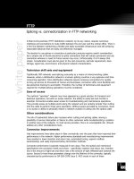
Routing Tables for an Example Scenario
Routings from A
To
A
B
C
D
E
Link
local
1
1
3
1
Routings from B
Cost
0
1
2
1
2
To
A
B
C
D
E
Link
1
local
2
1
4
Routings from C
Cost
1
0
1
2
1
To
A
B
C
D
E
Link
2
2
local
5
5
Cost
2
1
0
2
1
Links
A
Routings from D
1
3
Routings from E
To
Link
Cost
To
Link
Cost
A
B
C
D
E
3
3
6
local
6
1
2
2
0
1
A
B
C
D
E
4
4
5
6
local
2
1
1
1
0
D
Routers
B
4
6
E
2
C
5
Hosts or local
networks
16
2/17/2016
Distance Vector Algorithm –
Updating the Connectivity Information
Connectivity is updated by exchanging routing table
Router Information Protocol (RIP) is used for sending update messages
1. Send routing table to neighboring routers
Periodically, or when local table changes
2. When a neighbor’s routing table is received:
Case
If the received routing table …
1
Has a new destination that is not in the local routing table
2
Has a better-cost route to a destination in the local routing table
3
Has a more recent information
Updates to the local routing
table
Update the Cost and Link
Update the Cost
Update the Cost and Link
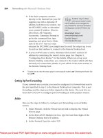
Pseudocode for RIP
Send: Each t seconds or when Tl changes, send Tl on each non-faulty outgoing link.
Receive: Whenever a routing table Tr is received on link n:
for all rows Rr in Tr {
if (Rr.link != n) {
Rr.cost = Rr.cost + 1; // Update cost
Rr.link = n; // Update next-hop
if (Rr.destination is not in Tl) {
add Rr to Tl; // add new destination to Tl Case 1
}
else for all rows Rl in Tl {
if (Rr.destination = Rl.destination) {
// Rr.cost < Rl.cost : remote node has better route
Case 2
// Rl.link = n : information is more recent
Case 3
if (Rr.cost < Rl.cost OR Rl.link = n) {
Rl = Rr;
}
}
}
}
}
A
B
1
3
4
D
E
6
2
5
C
Tl at A
Routing table at router A
To
Link
Cost
A
local
0
D
3
1
C
3
3
Tr recvd @ A from B on
link n=1
To
Routing table of router B
Link
Cost
A
1
B
local
0
C
2
1
1
17
2/17/2016
Summary: Routing over Internet
Each machine over the Internet is identified by an IP Address
Source machine transmits the packet over its local network
Intermediate routers examine the packet, and forward it to the best next-hop router
If the destination is directly attached to the local network of a router, the router forwards
the packet over the respective local network
Routers exchange information to keep an up-to-date information about the network
Source
Destination
Layers that we will study today
1.
2.
3.
4.
Physical layer
Data-link layer
Network layer
Transport layer
18
2/17/2016
Transport Layer
Transport layer protocols provide end-to-end communication for
applications
This is the lowest layer where messages (rather than packets) are handled
Messages are addressed to communication ports attached to the
processes
Transport layer multiplexes each
packet received to its respective port
Destination machine
P1
P2
P3
Transport layer protocol
Network layer protocol
Simple Transport Layer Protocols
Simple transport protocols provide the following services
1.
2.
Multiplexing Service
Connection-less Communication: The sender and receiver processes do not
initiate a connection before sending the message
Each message is encapsulated in a packet (also called as datagram)
Messages at the receiver can be in different order than the one sent by
the sender
e.g., User Datagram Protocol (UDP)
Source machine
P1
P1
UDP protocol
Destination machine
P3
P1
P2
P3
UDP protocol
19
2/17/2016
Transport Control Protocol (TCP)
Advanced transport layer protocols typically provide more services than simple
multiplexing
Transmission Control Protocol (TCP) is a widely-used protocol that provides
three additional services:
1.
2.
3.
Connection-oriented Communication
Reliability
Congestion Control
1. Connection-Oriented Communication
Sender and receiver will handshake before sending the messages
Handshake helps to set-up connection parameters, and to allocate resources at
destination to receive packets
Destination provides in-order delivery of messages to process
Destination will buffer the packets until previous packets are received
Delivers packets to the process in the order that the sender had sent
Source machine
P1
P1
Destination machine
P1
P3
P2
P3
Shall I send?
TCP protocol
TCP protocol
OK. Start sending
20
2/17/2016
2. Reliability
Packets may be lost in the network due to buffer overflows at the
router or transmission error(s)
In TCP, destination sends an ACK to the sender
If ACK is not received at the sender, the sender will infer a packet error,
and retransmit the packet
3. Congestion Control
The capacity of a network is limited by the individual communication links and
routers
Limited buffer space and link-bandwidth
What happens if a source transmits packets at a rate that is greater than the
capacity of the network?
Packet drops at intermediate routers. No ACK received at source
Source retransmits
More packets build-up on router queue
Network collapses
21
2/17/2016
3. Congestion Control (Cont’d)
To avoid congestion, two functionalities are adopted
1.
Detect congestion at routers:
If a router expects a buffer overflow, it typically follows one of the two strategies
– Drop packets at the router. Sources will regulate after observing packet loss
– Send an “Explicit Congestion Notification (ECN)” packet to the sender
2. Regulate input at sources:
If the TCP-sender concludes congestion (e.g., it receives an ECN packet), then it
reduces its sending rate
Next class
Examine Inter-process Communication in distributed systems
Examine IPCs through Socket API and Remote Invocations
Analyze concepts and middleware that support Message-oriented Communication
22
2/17/2016
References
/> /> /> /> /> />
23