Softswitch Architecture for VoIP
Bạn đang xem bản rút gọn của tài liệu. Xem và tải ngay bản đầy đủ của tài liệu tại đây (2.35 MB, 339 trang )
Source: Softswitch Architecture for VoIP
CHAPTER
1
Introduction
Downloaded from Digital Engineering Library @ McGraw-Hill (www.digitalengineeringlibrary.com)
Copyright © 2004 The McGraw-Hill Companies. All rights reserved.
Any use is subject to the Terms of Use as given at the website.
Introduction
2
Chapter 1
In 2000, the telecommunications boom went bust, and the reason was that
new market entrants, known as Competitive Local Exchange Carriers
(CLECs), were forced to compete with Incumbents Local Exchange Carriers
(ILECs) on the terms of the incumbents. The failure of the CLECs resulted
in a net investment loss of trillions of dollars, adversely affecting capital
markets and severely depressing the overall telecommunications economy,
as well as saddling subscribers with artificially high rates. The chief
expense for a new market entrant was purchasing and maintaining one or
more Class 5 switches (local service providers) or Class 4 switches (longdistance service providers). These switches cost millions of dollars to purchase and came with expensive maintenance contracts. These switches
were also very large and required expensive central office space. Faced with
competing for thin margins on local telephone service or thinner longdistance margins against incumbents who enjoyed strong investor support
and long depreciation schedules on capital equipment, the demise of many
new market entrants was foretold by their balance sheets.
The Telecommunications Act of 1996 aimed to introduce competition into
the local loop by legally requiring the incumbents to lease space on their
switches and in their central offices to any and all competitors. New market
entrants first found themselves stonewalled in the courts by the incumbents when attempting to gain legal access to the incumbent’s facilities.
Once legal access had been gained to the incumbents’ switching facilities,
the incumbents conveniently forgot the orders or otherwise sabotaged the
operations of the CLECs in the incumbents’ switching facilities.
Given firstly the astronomical expense of buying and installing Class 4
or 5 switches followed by the legal obstacle of gaining access to Public
Switched Telephone Network (PSTN), it is little wonder that six years after
the passage of the Telecommunications Act of 1996 only nine percent of
American residential phone lines are handled by competitive carriers.
Given this dismal figure, it is clear that regulatory agencies such as the
Federal Communications Commission (FCC) and the utilities commissions
of the 50 states have failed to adequately enforce either the letter or spirit
of the Telecommunications Act as regards introducing competition in the
local loop. Six years after the passage of the Act, 91 percent of all American
households have their choice of telephone service providers: the Regional
Bell Operating Company, the Regional Bell Operating Company, or the
Regional Bell Operating Company.
A competitive local loop environment has two apparently insurmountable obstacles: (1) the high cost of Class 4 and 5 switches and (2) gaining
access to the local loop network. As of 2002, despite the guarantees contained in the Telecommunications Act of 1996, it appears obvious that com-
Downloaded from Digital Engineering Library @ McGraw-Hill (www.digitalengineeringlibrary.com)
Copyright © 2004 The McGraw-Hill Companies. All rights reserved.
Any use is subject to the Terms of Use as given at the website.
Introduction
Introduction
3
petition will never come in the local loop but will have to come to the local
loop in the form of an alternative network. The expense of building and
maintaining a competitive network based on Class 4 and 5 switches prohibits a financially successful competitive local loop operation. The only way
consumers will enjoy the benefits of competition in the local loop is when
alternative technology in switching and, secondarily, access, enable a competitor a lower barrier to entry and exit.
The primary problem for competitors to the incumbent telephone companies has been access to the network that consists of copper wires radiating from the central office (where Class 5 and 4 switches are located) to the
residence or business. Although a variety of wires provides access to a residence (telephone, cable TV, and electrical) and wireless telephone service
has exploded in popularity worldwide, until recently all voice services
required expensive Class 5 switches for local service and Class 4 switches
for long distance. If telecommunications consumers are to enjoy the benefits
of competition in their local loop, an ability to bypass the telephone company central office will have to emerge in the market. This will require an
alternative switching architecture and a means of access (cable TV, wireless, and so on).
The lack of competition in and to the local loop brings forth the specter
of another problem raised by a monolithic telecommunications structure.
What happens when major hubs of the PSTN are destroyed in natural disasters, terrorist attacks, or other force majeurs? The September 11th attack
on the World Trade Center has served to focus attention on the vulnerability of the legacy, circuit-switched telephone network. Verizon, the largest
telephone company, had five central offices that served some 500,000 telephone lines south of 14th Street in Lower Manhattan. More than six million
private circuits and data lines passed through switching centers in or near
the World Trade Center. AT&T and Sprint switching centers in the WTC
were destroyed. Verizon lost two WTC-specific switches in the towers, and
two nearby central offices were knocked out by debris, fire, and water damage. Cingular Wireless lost six towers and Sprint PCS lost four. Power failures interrupted service at many other wireless facilities.1 Verizon further
estimates 300,000 voice business lines, 3.6 million data circuits, and 10 cellular towers were destroyed or disrupted by the events of September 11th,
which equates to phone and communications service interruption for
20,000 residential customers and 14,000 businesses.2
1
Telecom Update #300, September 17, 2001, www.angustel.ca/update/up300.html.
Naraine, Ryan. “Verizon Says WTC Attacks May Hurt Bottom Line,” Silicon Alley News,
www.atnewyork.com/news/article/0,1471,8471_897461,00.html.
2
Downloaded from Digital Engineering Library @ McGraw-Hill (www.digitalengineeringlibrary.com)
Copyright © 2004 The McGraw-Hill Companies. All rights reserved.
Any use is subject to the Terms of Use as given at the website.
Introduction
Chapter 1
4
Business and residential customers of these service providers had no
backup to these networks. They were without service for weeks after the
disaster. Financial losses and inconvenience as a result of this extended outage in terms of dollars and cents is incalculable. These customers had
bought into the telco myth of the invincibility of the PSTN.
The American PSTN can be described as having a centralized architecture. The telephone companies have not built redundancy into their networks. Almost all cities and towns across the nation rely on one hub or
central office, meaning that if that hub were destroyed, that city would lose
all land-line telephone connectivity with the outside world. Even with the
growth of CLECs, fewer than 10 percent of those CLECs have facilities
truly separate from the RBOCS. Between 1990 and 1999, the number of
RBOC central offices grew less than one percent to a nationwide total of
9,968, while the total number of phone lines grew by 34 percent according
to the FCC.3
This trend toward a more centralized infrastructure poses the risk of
thousands if not millions of subscribers being left without phone service
when their central office suffers a catastrophic casualty. The only real
backup for many subscribers when their central office fails is a cell phone.
The introduction of an alternative network infrastructure offers backup to
the subscriber in the event of PSTN failure.
Softswitch as an Alternative to
Class 4 and Class 5
Although too late for the failed new market entrants of the telecom boom of
the late 1990’s, new technologies have arrived on the market that provide a
low-cost alternative to Class 4 and 5 switches in both purchase price and
cost of maintenance. These technologies are Voice over Internet Protocol
(VoIP) and softswitch. Softswitch provides the call control or intelligence for
managing a call over an Internet Protocol (IP) or other network. Industry
traditionalists disparage these technologies as lacking the qualities of the
Class 4 and 5 switches that made them the standards of the industry for
the last 25 years. Those qualities are reliability, scalability, quality of service
(QoS), features, and signaling. Many have argued that VoIP and softswitch
3
Young, Shawn, and Dennis Berman. “Trade Center Attack Shows Vulnerability of Telecom Network,” Wall Street Journal, October 19, 2001, p.1.
Downloaded from Digital Engineering Library @ McGraw-Hill (www.digitalengineeringlibrary.com)
Copyright © 2004 The McGraw-Hill Companies. All rights reserved.
Any use is subject to the Terms of Use as given at the website.
Introduction
Introduction
5
technologies must match Class 4 and 5 switches in such qualities before
their deployment in a market environment is feasible. That time has come.
Not only do VoIP and softswitch compare favorably in function and quality with Class 4 and 5 switching, but they deliver services not possible with
Class 4 and 5 switches. This could potentially generate additional revenues
for service providers, making them more profitable than incumbent service
providers armed with Class 4 and 5 switches.
Reliability
The chief concern service providers have when comparing competitive technology to Class 4 and 5 switches is reliability. Class 4 and 5 switches have
a reputation for the “five 9s” of reliability. That is, they will be in service
99.999 percent of the time. Engineering a voice-switching solution to
achieve five nines is neither black magic nor a mandate from heaven on
golden tablets. It is a matter of meticulously engineering into the solution
the elements of redundancy, no single point of failure, and Network Equipment Building Standards (NEBS) to a point where, when figuring in
planned downtime, the solution has five minutes or less of downtime per
year. Many softswitch solutions now offer “five 9s” or better reliability.
Scalability
Of secondary importance to service providers is the scalability of a technological competitor to a Class 4 or 5 switch. To compete with a Class 4 or 5
switch, a softswitch solution must scale up to 100,000 DS0s (phone lines or
ports). Softswitch solutions, by virtue of new, high-density media gateways,
now match or exceed 100,000 DS0s in one 7-foot rack, as opposed to the 39
racks that it takes a Class 4 or 5 switch to make that many DS0s. One significant advantage of softswitch solutions over Class 4 and 5 switches in
regards to scalability is they can scale down to as little as two-port media
gateways or even one port in the case of IP handsets, allowing unlimited
flexibility in deployment. The minimum configuration for a Class 4 switch,
for example, is 480 DS0s.
Quality of Service (QoS)
Early VoIP applications garnered a reputation for poor QoS. First available
in 1995, these applications were often characterized by using personal
Downloaded from Digital Engineering Library @ McGraw-Hill (www.digitalengineeringlibrary.com)
Copyright © 2004 The McGraw-Hill Companies. All rights reserved.
Any use is subject to the Terms of Use as given at the website.
Introduction
Chapter 1
6
computers with microphones and speakers over the public Internet. The
calls were often dropped and the voice quality was questionable. Vast
improvements in IP networks over the last seven years coupled with
advances in media gateway technologies now deliver a QoS that matches or
exceeds that delivered via Class 4 and 5 switches over the PSTN.
Signaling
An element of the PSTN that was designed to deliver good QoS and thousands of features is Signaling Service 7 (SS7). The interfacing of SS7 and IP
networks necessary to deliver calls that travel over both the PSTN and an
IP network is a significant challenge. Much progress has been made, including the emergence of a new technology that is roughly the equivalent of SS7
designed to operate with IP networks known as SigTran. In addition, the
VOIP industry has new protocols such as the Session Initiation Protocol
(SIP) that matches or exceeds SS7 in signaling capabilities.
Features
Many proponents of the PSTN dismiss VoIP and softswitch solutions with
the interrogatory “Where’s the 3,500 5ESS features?” referring to Lucent
Technologies #5 Electronic Switching System (5ESS) Class 5 switch, which
is reported to have approximately 3,500 calling features. An interrogation
with Lucent Technologies did not produce a list of what each of those 3,500
features are or do. It is highly questionable as to whether each and every
one of those 3,500 features is absolutely necessary to the successful operation of a competitive voice service. Telcos that require new features must
contract with the switch vendor (in North America that is Lucent Technologies in 90 percent of the Class 5 market) to obtain new features. Obtaining those new features from the switch vendor will require months if not
years of development and hundreds of thousands of dollars.
Softswitch solutions are often based on open standards and use software
applications such as Voice XML (VXML) to write new features. Service
providers using softswitch solutions can often write their own features in
house in a matter of days. Service providers can also obtain new features
from third-party software vendors. Given this ease and economy of developing new features, the question arises, “Why limit yourself to a mere 3,500
features? Why not 35,000 or more features?”
This ease and flexibility in deploying new features in a softswitch solution offers a service provider the ability to quickly deploy high-margin feaDownloaded from Digital Engineering Library @ McGraw-Hill (www.digitalengineeringlibrary.com)
Copyright © 2004 The McGraw-Hill Companies. All rights reserved.
Any use is subject to the Terms of Use as given at the website.
Introduction
Introduction
7
tures that generate revenues not possible with Class 4 or 5 switches. In a
Net Present Value calculation, a softswitch solution, given its lower cost of
acquisition and operation coupled with an ability to generate greater revenues, will win over a Class 4 or 5 solution.
Regulatory Implications
The regulatory environment in the American telecommunications market is
sympathetic to VoIP and softswitch solutions. Long-distance VOIP calls in the
United States are immune to access fees and Universal Service Fund (USF)
levies. VoIP as a bypass technology initially encountered some resistance in
countries where incumbent service providers had much to lose to the bypass
operations. However, the privatization of national telephone companies and
a worldwide movement toward unbundled local loop (ULL) gives impetus to
the adoption of VoIP and softswitch technologies as voice technologies that
can be quickly and relatively inexpensively deployed, contributing to an
improved teledensity and its resulting improved economic infrastructure.
Economic Advantage of Softswitch
Given the previous advantages of a softswitch over a Class 4 or 5 switch in
terms of scalability, reliability, QoS, signaling, and features, a softswitch has
one more advantage over Class 4 and 5: price. A softswitch solution is considerably less expensive both in terms of acquisition and operation. This
presents a lower barrier to entry and exit for a competitive service provider.
A lower barrier to entry and exit allows alternative service providers to
enter the market. Some types of service providers that could be encouraged
to offer voice services in competition to incumbent telephone service
providers (local and long distance) include Internet service providers (ISPs),
cable TV companies, electric utility companies, application service providers
(ASPs), municipalities, and wireless service providers.
Disruptive or Deconstructive
Technology?
In his 2000 business book, The Innovator’s Dilemma, author Clayton Christensen describes how disruptive technologies have precipitated the failure
Downloaded from Digital Engineering Library @ McGraw-Hill (www.digitalengineeringlibrary.com)
Copyright © 2004 The McGraw-Hill Companies. All rights reserved.
Any use is subject to the Terms of Use as given at the website.
Introduction
8
Chapter 1
of leading products, and their associated and well-managed firms. Christensen defines criteria to identify disruptive technologies regardless of their
market. These technologies have the potential to replace mainstream technologies as well as their associated products and principal vendors. Disruptive technologies, abstractly defined by Christensen, are “typically
cheaper, simpler, smaller, and, frequently, more convenient” than their
mainstream counterparts.
Softswitch, relative to Class 4 and 5 switches, is a disruptive technology.
For the competitive service provider, softswitch is “cheaper, simpler, smaller,
and frequently more convenient” than Class 4 or 5. In order for a technology to be truly disruptive, it must “disrupt” an incumbent vendor or service
provider. Some entity must go out of business before a technology can be
considered “disruptive.” Although it is too early to point out a switch vendor
or incumbent service provider that has been driven out of business by
softswitch, softswitch technologies are potentially disruptive to both incumbent telephone companies and Class 4 and 5 switch vendors. It can also be
argued that the telephone industry has been “deconstructed” by the Internet or Internet-related technologies. Instead of making long-distance calls
or sending faxes over the PSTN, business people now send emails or use
web sites. Long-distance calls may be placed over VoIP networks. This
decreases demand on the legacy telephone network and also decreases
demand for telephone switching equipment.
This book describes how softswitch meets or exceeds Class 4 and 5
switch technologies and poses a potentially disruptive scenario for Class 4
and 5 vendors and telephone service providers. In a market economy, it is
inevitable that if competition cannot come in the local loop it will surely
come to the local loop. Given that softswitch solutions match Class 4 and 5
switches in terms of reliability, scalability, QoS, signaling, and features
while having well-defined advantages over Class 4 and 5, softswitch provides the crucial avenue for competitive service providers to enter telecommunications markets worldwide.
Downloaded from Digital Engineering Library @ McGraw-Hill (www.digitalengineeringlibrary.com)
Copyright © 2004 The McGraw-Hill Companies. All rights reserved.
Any use is subject to the Terms of Use as given at the website.
Source: Softswitch Architecture for VoIP
CHAPTER
2
The Public
Switched
Telephone
Network
(PSTN)
Downloaded from Digital Engineering Library @ McGraw-Hill (www.digitalengineeringlibrary.com)
Copyright © 2004 The McGraw-Hill Companies. All rights reserved.
Any use is subject to the Terms of Use as given at the website.
The Public Switched Telephone Network (PSTN)
Chapter 2
10
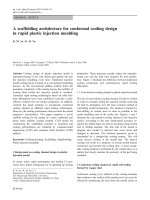
An understanding of the workings of the Public Switched Telephone Network (PSTN) is best grasped by understanding its three major components:
access, switching, and transport (see Figure 2-1). Each element has evolved
over the 100-plus year history of the PSTN. Access pertains to how a user
accesses the network. Switching refers to how a call is “switched” or routed
through the network, and transport describes how a call travels or is “transported” over the network.
Access
Access refers to how the user accesses the telephone network. For most
users, access is gained to the network via a telephone handset. Transmission and reception is via diaphragms where the mouthpiece converts the air
pressure of voice into an analog electromagnetic wave for transmission to
the switch. The earpiece performs this process in reverse. The most
sophisticated aspect of the handset is its Dual-Tone Multifrequency (DTMF)
function, which signals the switch by tones. The handset is usually connected to the central office (where the switch is located) via copper wire
known as twisted pair because, in most cases, it consists of a twisted pair of
copper wire. The stretch of copper wire connects the telephone handset to
the central office. Everything that runs between the subscriber and the central office is known as outside plant. Telephone equipment at the subscriber
end is called customer premise equipment (CPE).
Figure 2-1
The three
components of a
telephone network:
access, switching,
and transport
Access
Switching
Transport
Access
Switching
Downloaded from Digital Engineering Library @ McGraw-Hill (www.digitalengineeringlibrary.com)
Copyright © 2004 The McGraw-Hill Companies. All rights reserved.
Any use is subject to the Terms of Use as given at the website.
The Public Switched Telephone Network (PSTN)
The Public Switched Telephone Network (PSTN)
11
Switching
The PSTN is a star network; that is, every subscriber is connected to
another via at least one if not many hubs known as offices. In those offices
are switches. Very simply, local offices are used for local service connections
and tandem offices for long-distance service. Local offices, better known
as central offices, use Class 5 switches, and tandem offices use Class
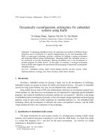
4 switches. Figure 2-2 details the relationship between Class 4 and 5
switches. A large city might have several central offices. Denver (population
2 million), for example, is estimated to have almost 40 central offices. Central offices in a large city often take up much of a city block and are recognizable as large brick buildings with no windows.
The first telephone switches were human. Taking a telephone handset off
hook alerted a telephone operator of the caller’s intention to place a call.
The caller informed the operator of their intended called party and the
operator set up the call by manually connecting the two parties.
Mechanical switching is credited to Almon Stowger, an undertaker in
Kansas City, Missouri, who realized he was losing business when families
of the deceased picked up their telephone handset and simply asked the
operator to connect them with “the undertaker.” The sole operator in this
Legacy Networks
Figure 2-2
The traditional
relationship of
Class 4, Class 5, and
data networks
Web Sites
Data
IP Network
Class 4 Switch
Class 5 Switch
PSTN
Voice
SS7
Class 4 Switch
Class 5 Switch
TDM Circuits
IP Circuits
Downloaded from Digital Engineering Library @ McGraw-Hill (www.digitalengineeringlibrary.com)
Copyright © 2004 The McGraw-Hill Companies. All rights reserved.
Any use is subject to the Terms of Use as given at the website.
The Public Switched Telephone Network (PSTN)
Chapter 2
12
town was engaged to an undertaker competing with Stowger. This competing undertaker had promised to marry the operator once he had the financial means to do so. The operator, in turn, was more than willing to help him
achieve that goal.
Stowger, realizing he was losing business to his competitor due to the
intercession of the telephone operator, proceeded to invent an electromechanical telephone handset and switch that enabled the caller, by virtue
of dialing the called party’s number, to complete the connection without
human intervention. Telephone companies realized the enormous savings
in manpower (or womanpower as the majority of telephone operators at the
time were women) by automating the call setup and takedown process.
Stowger switches (also known as crossbar switches) can still be found in the
central offices of rural America and lesser developed countries.
Stowger’s design remained the predominant telephone switching technology until the mid-1970s. Beginning in the ‘70s, switching technology
evolved to mainframe computers; that is, no moving parts were used and
the computer telephony applications made such features as conferencing
and call forwarding possible. In 1976, AT&T installed its first #4 Electronic
Switching System (4ESS) tandem switch. This was followed shortly thereafter with the 5ESS as a central office switch. ESS central office switches
did not require a physical connection between incoming and outgoing circuits. Paths between the circuits consisted of temporary memory locations
that enabled the temporary storage of traffic. For an ESS system, a computer controls the assignment, storage, and retrieval of memory locations so
that a portion of an incoming line (time slot) could be stored in temporary
memory and retrieved for insertion to an outgoing line. This is called a time
slot interchange (TSI) memory matrix. The switch control system maps specific time slots on an incoming communication line (such as a DS3) to
specific time slots on an outgoing communication line.1
Class 4 and 5 Switching
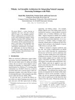
Class 4 and 5 switches are the “brains” of the PSTN. Figure 2-3 illustrates
the flow of a call from a handset to a Class 5 switch, which in turn hands
the call off to a Class 4 switch for routing over a long-distance network.
That call may be routed through other Class 4 switches before terminating
at the Class 5 switch at the destination end of the call before being passed
1
Harte, Lawrence. Telecom Made Simple. Fuquay-Varina, NC: APDG Publishing, 2002.
Downloaded from Digital Engineering Library @ McGraw-Hill (www.digitalengineeringlibrary.com)
Copyright © 2004 The McGraw-Hill Companies. All rights reserved.
Any use is subject to the Terms of Use as given at the website.
The Public Switched Telephone Network (PSTN)
The Public Switched Telephone Network (PSTN)
13
Class Network and Relationship to Class 5
Switching
Figure 2-3
Relationship of Class
4 and 5 switching
Class 4 Switch Denver
Class 4 Switch St. Louis
Class 5 Switch Denver
Class 4 Switch Chicago
Class 5 Switch Chicago
on to the terminating handset. Class 5 switches handle local calling and
Class 4 switches handle long-distance calls. The performance metrics for
the Class 4 and 5 have been reliability, scalability, quality of service (QoS),
signaling, and features.
Class 4 and 5 Architecture One reason for the reputation of Class 4
and 5 switches being reliable is that they have been tested by time in the
legacy market. Incremental improvements to the 4ESS included new interfaces, hardware, software, and databases to improve Operations, Administration, Maintenance, and Provisioning (OAM&P). The inclusion of the 1A
processor improved memory in the 4 and 5ESS mainframe, allowing for
translation databases. Ultimately, those databases were interfaced with the
Centralized Automatic Reporting on Trunks (CAROT). Later, integrated circuit chips replaced the magnetic core stores and improved memory and
boosted the Busy Hour Call Attempt (BHCA) capacity to 700,000 BHCAs.2
Class 4 and 5 Components The architecture of the Class 4 and 5 switch
is the product of 25-plus years of design evolution. For the purposes of this
discussion, the Nortel DMS-250, one of the most prevalent products in the
North American Class 4 market, is used as a real-world example. The other
2
Chapuis, Robert, and Amos Joel. “In the United States, AT&T’s Digital Switch Entry No. 4 ESS,
First Generation Time Division Digital Switch.” Electronics, Computers, and Telephone Systems.
New York: North Holland Publishing, 1990, p. 337—338.
Downloaded from Digital Engineering Library @ McGraw-Hill (www.digitalengineeringlibrary.com)
Copyright © 2004 The McGraw-Hill Companies. All rights reserved.
Any use is subject to the Terms of Use as given at the website.
The Public Switched Telephone Network (PSTN)
Chapter 2
14
leading product in this market is the 4ESS from Lucent Technologies. For
local offices or Class 5, the most prevalent product is the 5ESS from Lucent.
DMS-250 hardware, for example, is redundant for reliability and decreased
downtime during upgrades. It has a reliability rating of 99.999 percent (the
five 9s), which meets the industry metric for reliability. The modular design
of the hardware enables the system to scale from 480 to over 100,000 DS0s
(individual phone lines). The density, or number of phone lines the switch
can handle, is one metric of scalability. The DMS-250 is rated at 800,000
BHCAs. Tracking BHCAs on a switch is a measure of call-processing capability and is another metric for scalability.
Key hardware components of the DMS-250 system include the DMS
core, switch matrix, and trunk interface. The DMS core is the central processing unit (CPU) and memory of the system, handling high-level call processing, system control functions, system maintenance, and the installation
of new switch software.
The DMS-250 switching matrix switches calls to their destinations. Its
nonblocking architecture enables the switch to communicate with peripherals through fiber optic connections. The trunk interfaces are peripheral
modules that form a bridge between the DMS-250 switching matrix and the
trunks it serves. They handle voice and data traffic to and from customers
and other switching systems. DMS-250 trunk interfaces terminate DS-1,
Integrated Services Digital Network (ISDN) Primary Rate Interface (PRI),
X.75/X.75 packet networking, and analog trunks. They also accommodate
test and service circuits used in office and facility maintenance. It is important to note that the Class 4 switching matrix is a part of the centralized
architecture of the Class 4. Unlike the media gateways in a softswitch solution, it must be collocated with the other components of the Class 4.
DMS-250 billing requires the maintenance of real-time, transactionbased billing records for many thousands of customers and scores of variants in service pricing. The DMS-250 system automatically provides
detailed data, formats the data into call detail records, and constructs bills.3
Private Branch Exchange (PBX)
As the name would imply, a private branch exchange (PBX) is a switch
owned and maintained by a business with many (20 or more) users. A key
3
Nortel Networks. “Product Service Information-DMS300/250 System Advantage.” www.
nortel.com, 2001.
Downloaded from Digital Engineering Library @ McGraw-Hill (www.digitalengineeringlibrary.com)
Copyright © 2004 The McGraw-Hill Companies. All rights reserved.
Any use is subject to the Terms of Use as given at the website.
The Public Switched Telephone Network (PSTN)
The Public Switched Telephone Network (PSTN)
15
system is used by smaller offices. PBXs and key systems today are computer based and enable soft changes to be made through an administration
terminal or PC. Unless the business has a need for technical telecommunications personnel on staff for other reasons, the business will normally contract with their vendor for routine adds, moves, and changes of telephone
equipment.
PBX systems are often equipped with key assemblies and systems,
including voice mail, call accounting, a local maintenance terminal, and a
dial-in modem. The voice mail system is controlled by the PBX and only
receives calls when the PBX software determines a message can be left or
retrieved. The call accounting system receives system message details on
all call activities that occur within the PBX. The local terminal provides
onsite access to the PBX for maintenance activities. The dial-in capability
also provides access to the PBX for maintenance activities.4
Centrex
After PBXs caught on in the industry, local exchange carriers began to lose
some of their more lucrative business margins. The response to the PBX
was Centrex. Centrex is a service offered by a local telephone service
provider (primarily to businesses) that enables the customer to have features that are typically associated with a PBX. These features include
three- or four-digit dialing, intercom features, distinctive line ringing for
inside and outside lines, voice mail, call-waiting indication, and others. Centrex services flourished and still have a place for many large, dispersed entities such as large universities and major medical centers.
One of the major selling points for Centrex is the lack of capital expenditure up front. That, coupled with the reliability associated with Centrex
due to its location in the telephone company central office, has kept Centrex
as the primary telephone system in many of the businesses referenced previously. PBXs, however, have cut into what was once a lucrative market for
the telephone companies and are now the rule rather than the exception for
business telephone service. This has come about because of inventive ways
of funding the initial capital outlay and the significantly lower operating
cost of a PBX versus a comparable Centrex offering.
4
Harte, Lawrence. Telecom Made Simple. Fuquay-Varina, NC: APDG Publishing, 2002.
Downloaded from Digital Engineering Library @ McGraw-Hill (www.digitalengineeringlibrary.com)
Copyright © 2004 The McGraw-Hill Companies. All rights reserved.
Any use is subject to the Terms of Use as given at the website.
The Public Switched Telephone Network (PSTN)
Chapter 2
16
Multiplexing
The earliest approach to getting multiple conversations over one circuit was
frequency division multiplexing (FDM). FDM was made possible by the vacuum tube where the range of frequencies was divided into parcels that were
distributed among subscribers. In the first FDM architectures, the overall
system bandwidth was 96 kHz. This 96 kHz could be divided among a number of subscribers into, for example, 5 kHz per subscriber, meaning almost
20 subscribers could use this circuit.
FDM is an analog technology and suffers from a number of shortcomings. It is susceptible to picking up noise along the transmission path. This
FDM signal loses its power over the length of the transmission path. FDM
requires amplifiers to strengthen the signal over that path. However, the
amplifiers cannot separate the noise from the signal and the end result is
an amplified noisy signal.
The improvement over FDM was time division multiplexing (TDM).
TDM was made possible by the transistor that arrived in the market in the
1950s and 1960s. As the name would imply, TDM divides the time rather
than the frequency of a signal over a given circuit. Although FDM was typified by “some of the frequency all of the time,” TDM is “all of the frequency
some of the time.” TDM is a digital transmission scheme that uses a small
number of discrete signal states. Digital carrier systems have only three
valid signal values: one positive, one negative, and zero. Everything else is
registered as noise. A repeater, known as a regenerator, can receive a weak
and noisy digital signal, remove the noise, reconstruct the original signal,
and amplify it before transmitting the signal onto the next segment of the
transmission facility. Digitization brings with it the advantages of better
maintenance and troubleshooting capability, resulting in better reliability.
Also, a digital system enables improved configuration flexibility.
TDM has made the multiplexer, also known as the channel bank, possible. In the United States, the multiplexer or “mux” enables 24 channels per
single four-wire facility. This is called a T-1, DS1, or T-Carrier. Outside
North America and Japan, it is 32 channels per facility and known as E1.
These systems came on the market in the early 1960s as a means to transport multiple channels of voice over expensive transmission facilities.
Voice Digitization via Pulse Code Modulation
One of the first processes in the transmission of a telephone call is the conversion of an analog signal into a digital one. This process is called pulse
Downloaded from Digital Engineering Library @ McGraw-Hill (www.digitalengineeringlibrary.com)
Copyright © 2004 The McGraw-Hill Companies. All rights reserved.
Any use is subject to the Terms of Use as given at the website.
The Public Switched Telephone Network (PSTN)
The Public Switched Telephone Network (PSTN)
17
code modulation (PCM). This is a four-step process consisting of pulse
amplitude modulation (PAM) sampling, companding, quantization, and
encoding.
Pulse Amplitude Modulation (PAM) The first stage in PCM is known
as PAM. In order for an analog signal to be represented as a digitally
encoded bitstream, the analog signal must be sampled at a rate that is
equal to twice the bandwidth of the channel over which the signal is to be
transmitted. As each analog voice channel is allocated 4 kHz of bandwidth,
each voice signal is sampled at twice that rate, or 8,000 samples per second. In a T-Carrier, the standard in North America and Japan, each channel is sampled every one eight-thousandth of a second in rotation, resulting
in the generation of 8,000 pulse amplitude samples from each channel
every second. If the sampling rate is too high, too much information is
transmitted and bandwidth is wasted. If the sampling rate is too low, aliasing may result. Aliasing is the interpretation of the sample points as a false
waveform due to the lack of samples.
Companding The second process of PCM is companding. Companding is
the process of compressing the values of the PAM samples to fit the nonlinear quantizing scale that results in bandwidth savings of more than 30
percent. It is called companding as the sample is compressed for transmission and expanded for reception.5
Quantization The third stage in PCM is quantization. In quantization,
values are assigned to each sample within a constrained range. In using a
limited number of bits to represent each sample, the signal is quantized.
The difference between the actual level of the input analog signal and the
digitized representation is known as quantization noise. Noise is a detraction to voice quality and it is necessary to minimize noise. The way to do
this is to use more bits, thus providing better granularity. In this case, an
inevitable trade-off takes place bewteen bandwidth and quality. More bandwidth usually improves signal quality, but bandwidth costs money. Service
providers, whether using TDM or Voice over IP (VoIP) for voice transmission will always have to choose between quality and bandwidth. A process
known as nonuniform quantization involves the usage of smaller
5
Shepard, Steven. SONET/SDH Demystified. New York: McGraw-Hill, 2001. p. 15—21.
Downloaded from Digital Engineering Library @ McGraw-Hill (www.digitalengineeringlibrary.com)
Copyright © 2004 The McGraw-Hill Companies. All rights reserved.
Any use is subject to the Terms of Use as given at the website.
The Public Switched Telephone Network (PSTN)
Chapter 2
18
quantization steps at smaller signal levels and larger quantization steps for
larger signal levels. This gives the signal greater granularity or quality at
low signal levels and less granularity (quality) at high signal levels. The
result is to spread the signal-to-noise ratio more evenly across the range of
different signals and to enable fewer bits to be used compared to uniform
quantization. This process results in less bandwidth being consumed than
for uniform quantization.6
Encoding The fourth and final process in PCM is encoding the signal.
This is performed by a codec (coder/decoder). Three types of codecs exist:
waveform codecs, source codecs (also known as vocoders), and hybrid
codecs. Waveform codecs sample and code an incoming analog signal
without regard to how the signal was generated. Quantized values of the
samples are then transmitted to the destination where the original signal
is reconstructed, at least to a certain approximation of the original. Waveform codecs are known for simplicity with high-quality output. The disadvantage of waveform codecs is that they consume considerably more
bandwidth than the other codecs. When waveform codecs are used at low
bandwidth, speech quality degrades markedly.
Source codecs match an incoming signal to a mathematical model of how
speech is produced. They use the linear predictive filter model of the vocal
tract, with a voiced/unvoiced flag to represent the excitation that is applied
to the filter. The filter represents the vocal tract and the voice/unvoiced flag
represents whether a voiced or unvoiced input is received from the vocal
chords. The information transmitted is a set of model parameters as
opposed to the signal itself. The receiver, using the same modeling technique in reverse, reconstructs the values received into an analog signal.
Source codecs also operate at low bit rates and reproduce a synthetically
sounding voice. Using higher bit rates does not result in improved voice
quality. Vocoders (source codecs) are most widely used in private and military applications.
Hybrid codecs are deployed in an attempt to derive the benefits from
both technologies. They perform some degree of waveform matching while
mimicking the architecture of human speech. Hybrid codecs provide better
voice quality at low bandwidth than waveform codecs. Table 2-1 provides an
outline of the different ITU codec standards and Table 2-2 lists the parameters of the voice codecs.
6
Collins, Daniel. Carrier Grade Voice Over IP. New York: McGraw-Hill, 2001. p. 95—96.
Downloaded from Digital Engineering Library @ McGraw-Hill (www.digitalengineeringlibrary.com)
Copyright © 2004 The McGraw-Hill Companies. All rights reserved.
Any use is subject to the Terms of Use as given at the website.
The Public Switched Telephone Network (PSTN)
The Public Switched Telephone Network (PSTN)
Table 2-1
Descriptions of
voice codecs (ITU)
Table 2-2
Parameters of voice
codecs
19
ITU Standard
Description
P.800
A subjective rating system to determine the Mean Opinion Score
(MOS) or the quality of telephone connections
G.114
A maximum one-way delay end to end for a VoIP call (150 ms)
G.165
Echo cancellers
G.168
Digital network echo cancellers
G.711
PCM of voice frequencies
G.722
7 kHz audio coding within 64 Kbps
G.723.1
A dual-rate speech coder for multimedia communications transmitting
at 5.3 and 6.3 Kbps
G.729
Coding for speech at 8 Kbps using conjugate-structure algebraic codeexcited linear-prediction (CS-ACELP)
G.729A
Annex A reduced complexity 8 Kbps CS-ACELP speech codec
H.323
A packet-based multimedia communications system
P.861
Specifies a model to map actual audio signals to their representations
inside the human head
Q.931
Digital subscriber signaling system number 1 ISDN user-network
interface layer 3 specification for basic call control
Standard
Data rate (Kbps)
Delay (ms)
MOS
Codec
G.711
64
0.125
4.8
Waveform
G.721, G.723, G.726
16,24,32,40
0.125
4.2
G.728
16
2.5
4.2
G.729
8
10
4.2
G.723.1
5.3, 6.3
30
3.5, 3.98
Popular Speech Codecs Codecs are best known for the sophisticated
compression algorithms they introduce into a conversation. Bandwidth
costs service providers money. The challenge for many service providers is
to squeeze as much traffic as possible into one “pipe,” that is one channel.
Most codecs allow multiple conversations to be carried on one 64 kbps channel. There is an inevitable trade off in compression for voice quality in the
Downloaded from Digital Engineering Library @ McGraw-Hill (www.digitalengineeringlibrary.com)
Copyright © 2004 The McGraw-Hill Companies. All rights reserved.
Any use is subject to the Terms of Use as given at the website.
The Public Switched Telephone Network (PSTN)
20
Chapter 2
conversation. The challenge for service providers is to balance the economics of compression with savings in bandwidth costs.
G.711 G.711 is the best-known coding technique in use today. It is a wave-
form codec and is the coding technique used in circuit-switched telephone
networks all over the world. G.711 has a sampling rate of 8,000 Hz. If
uniform quantization were to be used, the signal levels commonly found in
speech would be such that at least 12 bits per sample would be needed, giving it a bit rate of 96 Kbps. Nonuniform quantization is used with eight bits
used to represent each sample. This quantization leads to the well-known
64 Kbps DS0 rate. G.711 is often referred to as PCM. G.711 has two variants: A-law and mu-law. Mu-law is used in North America and Japan where
T-Carrier systems prevail. A-law is used everywhere else in the world. The
difference between the two is the way nonuniform quantization is performed. Both are symmetrical at approximately zero. Both A-law and mulaw offer good voice quality with a MOS of 4.3, with 5 being the best and 1
being the worst. Despite being the predominant codec in the industry, G.711
suffers one significant drawback; it consumes 64 Kbps in bandwidth. Carriers seek to deliver voice quality using little bandwidth, thus saving on
operating costs.
G.728 LD-CELP Code-Excited Linear Predictor (LD-CELP) codecs implement a filter and contain a codebook of acoustic vectors. Each vector
contains a set of elements in which the elements represent various characteristics of the excitation signal. CELP coders transmit to the receiving end
a set of information determining filter coefficients, gain, and a pointer to the
chosen excitation vector. The receiving end contains the same code book and
filter capabilities so that it reconstructs the original signal. G.728 is a
backward-adaptive coder as it uses previous speech samples to determine
the applicable filter coefficients. G.728 operates on five samples at one time.
That is, 5 samples at 8,000 Hz are needed to determine a codebook vector
and filter coefficients based upon previous and current samples. Given a
coder operating on five samples at a time, a delay of less than 1 millisecond
is the result. Low delay equals better voice quality.
The G.728 codebook contains 1,024 vectors, which requires a 10-bit index
value for transmission. It also uses 5 samples at a time taken at a rate of
8,000 per second. For each of those 5 samples, G.728 results in a transmitted bit rate of 16 Kbps. Hence, G.728 has a transmitted bit rate of 16 Kbps.
Another advantage here is that this coder introduces a delay of 0.625 milliseconds with an MOS of 3.9. The difference from G.711’s MOS of 4.3 is
imperceptible to the human ear. The bandwidth savings between G.728’s 16
Kbps per conversation and G.711’s 64 Kbps per conversation make G.728
very attractive to carriers given the savings in bandwidth.
Downloaded from Digital Engineering Library @ McGraw-Hill (www.digitalengineeringlibrary.com)
Copyright © 2004 The McGraw-Hill Companies. All rights reserved.
Any use is subject to the Terms of Use as given at the website.
The Public Switched Telephone Network (PSTN)
The Public Switched Telephone Network (PSTN)
21
G.723.1 ACELP G.723.1 ACELP can operate at either 6.3 Kbps or 5.3 Kbps
with the 6.3 Kbps providing higher voice quality. Bit rates are contained in
the coder and decoder, and the transition between the two can be made during a conversation. The coder takes a bank-limited input speech signal that
is sampled a 8,000 Hz and undergoes uniform PCM quantization, resulting
in a 16-bit PCM signal. The encoder then operates on blocks or frames of
240 samples at a time. Each frame corresponds to 30 milliseconds of speech,
which means that the coder causes a delay of 30 milliseconds. With a lookahead delay of 7.5 milliseconds, the total algorithmic delay is 37.5 milliseconds. G.723.1 gives an MOS of 3.8, which is highly advantageous in regards
to the bandwidth used. The delay of 37.5 milliseconds one way does present
an impediment to good quality, but the round-trip delay over varying
aspects of a network determines the final delay and not necessarily the
codec used.
G.729 G.729 is a speech coder that operates at 8 Kbps. This coder uses
input frames of 10 milliseconds, corresponding to 80 samples at a sampling
rate of 8,000 Hz. This coder includes a 5-millisecond look-ahead, resulting
in an algorithmic delay of 15 milliseconds (considerably better than
G.723.1). G.729 uses an 80-bit frame. The transmitted bit rate is 8 Kbps.
Given that it turns in an MOS of 4.0, G.729 is perhaps the best trade-off in
bandwidth for voice quality. The previous paragraphs provide an overview
of the multiple means of maximizing the efficiency of transport via the
PSTN. We find today that TDM is almost synonymous with circuit switching. Telecommunications engineers use the term TDM to describe a circuitswitched solution. A 64 Kbps G.711 codec is the standard in use on the
PSTN. The codecs described in the previous pages apply to VoIP as well.
VoIP engineers seeking to squeeze more conversations over valuable bandwidth have found these codecs very valuable in compressing VoIP conversations over an IP circuit.7
Signaling
Signaling describes the process of how calls are set up and torn down. Generally speaking, there are three main functions of signaling: supervision,
alerting, and addressing. Supervision refers to monitoring the status of a
line or circuit to determine if there is traffic on the line. Alerting deals with
the ringing of a phone indicating the arrival of an incoming call. Addressing is the routing of a call over a network. As telephone networks matured,
7
Ibid.
Downloaded from Digital Engineering Library @ McGraw-Hill (www.digitalengineeringlibrary.com)
Copyright © 2004 The McGraw-Hill Companies. All rights reserved.
Any use is subject to the Terms of Use as given at the website.
The Public Switched Telephone Network (PSTN)
Chapter 2
22
individual nations developed their proprietary signaling systems. Ultimately, there become a signaling protocol for every national phone service
in the world. Frankly, it is a miracle that international calls are ever completed given the complexity of interfacing national signaling protocols.
Signaling System 7 (SS7) For much of the history of circuit-switched
networks, signaling followed the same path as the conversation. This is
called Channel-Associated Signaling (CAS) and is still in wide use today.
R1 Multifrequency (MF) used in North American markets and R2 MultiFrequency Compelled (RFC) used elsewhere in the world are the best examples of this. Another name for this is in-channel signaling. The newer
technology for signaling is called Common Channel Signaling (CCS), also
known as out-of-band signaling. CCS uses a separate transmission path for
call signaling and not the bearer path for the call. This separation enables
the signaling to be handled in a different manner to the call. This enables
signaling to be managed by a network independent of the transport network. Figure 2-4 details the difference between CAS and CCS.
Figure 2-4
CAS and CCS
Speech and Signaling
Switch
Switch
Channel Associated Signaling
Signaling
S.T.P.
S.T.P.
Speech
Switch
Common Channel Signaling
Switch
8
Stallings, William. ISDN and Broadband ISDN with Frame Relay and ATM. New York: Prentice Hall, 1995. p.292.
Downloaded from Digital Engineering Library @ McGraw-Hill (www.digitalengineeringlibrary.com)
Copyright © 2004 The McGraw-Hill Companies. All rights reserved.
Any use is subject to the Terms of Use as given at the website.
The Public Switched Telephone Network (PSTN)
The Public Switched Telephone Network (PSTN)
23
Signaling System 7 (SS7) is the standard for CCS with many national
variants throughout the world (such as Mexico’s NOM-112). It routes control messages through the network to perform call management (setup,
maintenance, and termination) and network management functions.
Although the network being controlled is circuit switched, the control signaling is implemented using packet-switching technology. In effect, a
packet-switched network is overlaid on a circuit-switched network in order
to operate and control the circuit-switched network. SS7 defines the functions that are performed in the packet-switched network but does not dictate any particular hardware implementation.8
The SS7 network and protocol are used for the following:
■
Basic call setup, management, and tear down
■
Wireless services such as personal communications services (PCS),
wireless roaming, and mobile subscriber authentication
■
Local number portability (LNP)
■
Toll-free (800/888) and toll (900) wireline services
■
Enhanced call features such as call forwarding, calling party
name/number display, and three-way calling
■
Efficient and secure worldwide telecommunications
Signaling Links SS7 messages are exchanged between network elements over 56 or 64 Kbps bidirectional channels called signaling links. Signaling occurs out of band on dedicated channels rather than in-band on
voice channels. Compared to in-band signaling, out-of-band signaling provides faster call setup times (compared to in-band signaling using MF signaling tones), more efficient use of voice circuits, support for Intelligent
Network (IN) services that require signaling to network elements without
voice trunks (such as database systems), and improved control over fraudulent network usage.
Signaling Points Each signaling point in the SS7 network is uniquely
identified by a numeric point code. Point codes are carried in signaling messages exchanged between signaling points to identify the source and destination of each message. Each signaling point uses a routing table to select the
appropriate signaling path for each message. Three kinds of signaling points
are used in the SS7 network: service switching points (SSP), signal transfer
points (STP), and service control points (SCP), as shown in Figure 2-5.
SSPs are switches that originate, terminate, or tandem calls. An SSP
sends signaling messages to other SSPs to set up, manage, and release voice
Downloaded from Digital Engineering Library @ McGraw-Hill (www.digitalengineeringlibrary.com)
Copyright © 2004 The McGraw-Hill Companies. All rights reserved.
Any use is subject to the Terms of Use as given at the website.
The Public Switched Telephone Network (PSTN)
Chapter 2
24
Figure 2-5
SS7 signaling points
(Source: Performance
Technologies)
circuits required to complete a call. An SSP may also send a query message
to a centralized database (an SCP) to determine how to route a call (such as
a toll-free 1-800/888 call in North America). An SCP sends a response to the
originating SSP containing the routing number(s) associated with the
dialed number. An alternate routing number may be used by the SSP if the
primary number is busy or the call is unanswered within a specified time.
Actual call features vary from network to network and from service to
service.
Network traffic between signaling points may be routed via a packet
switch called an STP. An STP routes each incoming message to an outgoing
signaling link based on routing information contained in the SS7 message.
Because it acts as a network hub, an STP provides improved utilization of
the SS7 network by eliminating the need for direct links between signaling
points. An STP may perform global title translation, a procedure by which
the destination signaling point is determined from digits present in the signaling message (such as the dialed 800 number, the calling card number, or
mobile subscriber identification number). An STP can also act as a firewall
to screen SS7 messages exchanged with other networks.
Because the SS7 network is critical to call processing, SCPs and STPs
are usually deployed in mated-pair configurations in separate physical locations to ensure network-wide service in the event of an isolated failure.
Links between signaling points are also provisioned in pairs. Traffic is
shared across all links in the linkset. If one of the links fails, the signaling
traffic is rerouted over another link in the linkset. The SS7 protocol provides both error correction and retransmission capabilities to enable continued service in the event of signaling point or link failures.
SS7 Signaling Link Types Signaling links are logically organized by
link type (A through F) according to their use in the SS7 signaling network
(see Figure 2-6 and Table 2-3).
Downloaded from Digital Engineering Library @ McGraw-Hill (www.digitalengineeringlibrary.com)
Copyright © 2004 The McGraw-Hill Companies. All rights reserved.
Any use is subject to the Terms of Use as given at the website.