Rules of thumb for mechanical engineers
Bạn đang xem bản rút gọn của tài liệu. Xem và tải ngay bản đầy đủ của tài liệu tại đây (21.97 MB, 418 trang )
t
R U L E S O F THUM
F O R M E C H A N I C A L liEH
A m a n u a l of quick, a c c u r a t e s o l u t i o n s
t o everyday mechanical engineering problems
J. E d w a r d P o p e , E d i t o r
R U L E S O F THUMEI
FOR
MECHANICAL
ENGINEERS
Gulf Publishing Company
Houston, Texas
RULES OF THUMB FOR
MECHANICAL ENGINEERS
Copyright 8 1997 by Gulf Publishing Company,
Houston, Texas. All rights reserved. Printed in the
United States of America. This book, or parts thereof,
may not be reproduced in any form without permission
of the publisher.
1 0 9 8 7 6 5 4 3
Gulf Publishing Company
Book Division
P.O. Box 2608 0 Houston, Texas 77252-2608
Library of Congress Cataloging-in-PublicationData
Rules of thumb for mechanical engineers : a manual of
quick, accurate solutions to everyday mechanical
engineering problems / J. Edward Pope, editor ;in
collaboration with Andrew Brewington . . . [et al.].
p. cm.
Includes bibliographical references and index.
ISBN 0-88415-790-3 (acid-free paper)
1. Mechanical engineering-Handbooks, manuals,
etc. I. Pope, J. Edward, 1956- . 11. Brewington,
Andrew.
TJ151.R84 1996
621 4 - 2 0
96-35973
CIP
Printed on acid-free paper (=I.
iv
.
Friction Factor and Darcy Equation ...............................
Losses in Pipe Fittings and Valves..................................
Pipes in Series.................................................................
pipes in Parallel ..............................................................
1: Fluids 1
Fluid Properties
............................
Density. Specific Volume. Specific Weight.
Specific Gravity. and Pressure....................................
Surface Tension ..............................................................
Vapor Pressure ................................................................
Gas and Liquid Viscosity................................................
Bulk Modulus .................................................................
Compressibility...............................................................
Units and Dimensions.....................................................
Fluid Statics
Manometers and Pressure Measurements.......................
Hydraulic Pressure on Surfaces ......................................
Buoyancy ........................................................................
..............................................................
Basic Equations
........................................................
Continuity E q ~ t i o ........................................................
n
Euler’s Equation .............................................................
Bernoulli’s Equation .......................................................
Energy Equation .............................................................
Momentum Equation ......................................................
Moment-of-Momentum Equation...................................
Advanced Fluid Flow Concepts
...............
Dimensional Analysis and Similitude ............................
Nondimensional Parameters ...........................................
Equivalent Diameter and Hydraulic Radius ...................
Pipe Flow
...................................................................
2
Open-Channel Flow
2
2
2
.................................................
Frictionless Open-Channel Flow ....................................
Laminar Open-Channel Flow .........................................
Turbulent Open-Channel Flow .......................................
Hydraulic Jump...............................................................
3
3
3
3
4
.................................................
Fluid Measurements
Pressure and Velocity Measurements .............................
Flow Rate Measurement .................................................
Hot-wire and Thin-Film Anemometry...........................
Open-Channel Flow Measurements ...............................
Viscosity Measurements .................................................
4
4
5
Other TopiCS
5
..............................................................
Unsteady Flow, Surge, and Water Hammer....................
Boundary Layer Concepts ..............................................
Lift and Drag...................................................................
Oceanographic Flows .....................................................
5
5
6
6
6
6
7
.....................................................
Conduction................................................................
Introduction.........
7
7
8
Single Wall Conduction..................................................
Composite Wall Conduction...........................................
8
V
9
10
10
10
11
11
12
12
12
13
13
14
14
15
15
16
16
16
16
17
19
19
19
21
The Combined Heat Transfer Coefficient.......................
Critical Radius of Insulation...........................................
.................................................................
Convection
Dimensionless Numbers .................................................
Correlations.....................................................................
Typical Convection Coefficient Values ..........................
Radiation
23
24
26
26
......................
29
................
33
Finite Element Analysis
Boundary Conditions ......................................................
2D Analysis ....................................................................
Transient Analysis ..........................................................
Evaluating Results ..........................................................
Heat Exchanger Classification
............
............................................................
...............
.....................................................
.....................
......................
....................
....................
...................
............
........................................................
...................
....................
.......................
.................................................................
Basic Mechanical Seal Components
Sealing Points
Mechanical Seal Classifications
Basic Seal Designs
Basic Seal Arrangements
Basic Design Principles
Materials of Construction
Desirable Design Features
Equipment Considerations
Calculating Seal Chamber Pressure
Seal Flush Plans
Integral Pumping Features
Seal System Heat Balance
Flow Rate Calculation
References
29
30
30
31
33
36
38
40
42
Flow Regimes and Pressure Drop in Two-Phase
Heat Transfer
42
........................................................
4: Mechanical Seals. 66
27
27
29
Types of Heat Exchangers ..............................................
Shell-and-Tube Exchangers............................................
Tube Arrangements and Baffles .....................................
Shell Configurations.......................................................
Miscellaneous Data .........................................................
Flow Regimes .................................................................
Flow Maps ......................................................................
Estimating Pressure Drop ...............................................
42
46
48
...................
Phases of a Pure Substance.............................................
Thermodynamic Properties.............................................
Determining Properties...................................................
Types of Systems ............................................................
Types of Processes ..........................................................
The Zeroth Law of Thermodynamics.............................
................
First Law of Thermodynamics
Work ................................................................................
Heat .................................................................................
First Law of Thermodynamics for Closed Systems .......
First Law of Thermodynamics for Open Systems ..........
..............
Second Law of Thermodynamics
Reversible Processes and Cycles ....................................
67
67
68
68
72
74
77
79
80
81
82
85
87
89
91
5: Pumps and Compressors. 92
~~
~
Pump Fundamentals and Design
..............
Pump and Head Terminology .........................................
Pump Design Parameters and Formulas .........................
Types of Pumps...............................................................
Centrifugal Pumps ..........................................................
Net Positive Suction Head (NPSH) and Cavitation........
Pumping Hydrocarbons and Other Fluids ......................
Recirculation...................................................................
Pumping Power and Efficiency ......................................
Specific Speed of Pumps ................................................
Pump Similitude .............................................................
Performance Curves........................................................
Series and Parallel Pumping ...........................................
Design Guidelines...........................................................
Reciprocating Pumps ......................................................
3: Thermodynamics. 51
ThermodynamicEssentials
63
64
23
...................................................................
Emissivity .......................................................................
View Factors ...................................................................
Radiation Shields ............................................................
Diesel Cycle: Another Power Cycle ...............................
Gas Power Cycles with Regeneration.............................
22
22
52
52
53
55
56
56
57
58
58
58
58
58
Compressors
.............................................................
93
93
93
94
95
96
96
97
97
97
98
98
99
100
103
110
Definitions ......................................................................
110
Performance Calculations for Reciprocating
111
Compressors ...............................................................
Estimating Suction and Discharge Volume Bottle
Sizes for Pulsation Control for Reciprocating
Compressors ...............................................................
114
117
Compression Horsepower Determination.......................
Generalized Compressibility Factor ...............................
119
Centrifugal Compressor Performance Calculations ....... 120
Estimate HP Required to Compress Natural Gas ........... 123
Estimate Engine Cooling Water Requirements .............. 124
59
59
59
59
60
Thermodynamic Cycles
60
Basic Systems and Systems Integration .........................
Carnot Cycle ...................................................................
60
Rankine Cycle: A Vapor Power Cycle............................
61
Reversed Rankine Cycle: A Vapor Refrigeration Cycle. 61
Brayton Cycle: A Gas Turbine Cycle .............................
62
Otto Cycle: A Power Cycle ............................................
63
Thermodynamic Temperature Scale ...............................
Useful Expressions .........................................................
......................
vi
Estimate Fuel Requirements for Internal Combustion
Engines .......................................................................
References
Lubricant Selection.........................................................
Lubricating Methods.......................................................
. .
Relubncahon...................................................................
Cleaning. Preservation. and Storage...............................
124
................ ........................12A
...........
"
..................................
Mounting
6: Drivers. 125
..........................
........................
......................
....................
.......................
........................
..................
...................
.....................
.....................
.............
Motors: Efficiency
Motors: Starter Sizes
Motors: Service Factor
Motors: Useful Equations
Motors: Relative Costs
Motors: Overloading
Steam Wbines: Steam Rate
Steam mrbines: Efficiency
Gas Wbines: Fuel Rates
Gas Engines: Fuel Rates
Gas Expanders: Available Energy
Shafting...........................................................................
Housings .........................................................................
Bearing Clearance...........................................................
Seals................................................................................
126
127
127
128
128
129
129
129
130
132
132
.........................................................
.................................................................
Sleeve Bearings
References
Process Plant Pipe
Rating and Life
146
.............................
152
ABMA Definitions .........................................................
Fatigue Life.....................................................................
Life Adjustment Factors .................................................
.....................
Load and Speed Analysis
Equivalent Loads ............................................................
Contact Stresses..............................................................
Preloading.......................................................................
Special Loads ..................................................................
Effects of Speed ..............................................................
Lubrication
....................
190
Steel Pipe Design............................................................
Gas Pipe Lines ............................................................
Liquid pipe Lines........................................................
134
134
139
141
142
143
144
144
...........................
Ball Bearings ..................................................................
Roller Bearings ...............................................................
Standardization ...............................................................
Materials .........................................................................
...............................................................
General............................................................................
Oils..................................................................................
Greases............................................................................
175
177
179
Transportation Pipe Lines
190
190
192
195
........................................................
206
Pig-based Monitoring Systems.......................................
Coupons ..........................................................................
Manual Investigation ......................................................
Cathodic Protection ........................................................
Pressure Vessels
179
187
188
189
...............
Pipe Line Condition Monitoring
195
196
196
197
Stress Analysis................................................................
206
Failures in Pressure Vessels ............................................
207
Loadings .........................................................................
208
stress...............................................................................
209
procedure 1: General Vessel Formulas ...........................
213
Procedure 2: Stresses in Heads Due to Internal
Pressure.......................................................................
215
Joint Efficiencies (ASME Code) ....................................
217
Properties of Heads .........................................................
218
Volumes and Surface Areas of Vessel Sections.............. 220
Maximum Length of UnstiffenedShells ........................
221
Useful Formulas for Vessels ...........................................
222
Material SelectionGuide ................................................
224
References.......................................................................
225
8: Bearings. 145
Qpes of Bearings
166
169
172
174
....................................................
Definitions and Sizing ....................................................
Pipe Specifications..........................................................
Storing Pipe ....................................................................
Calculations to Use .........................................................
.
....................
.................
Bevel Gear Design ....................................................
Cylindrical Worm Gear Design ...............
Materials ...................................................................
s
w of Gear Qpes .....................
Buying Gears and Gear Drives ................
References .................................
166
9 Pipina and Pressure Vessels. 178
7: liearsJ33
Ratios and Nomenclature
Spur and Helical Gear Design
162
163
164
165
146
147
149
151
152
153
154
156
156
157
10: Tribology. 226
157
158
..............................................................
...................................................
Introduction
Contact Mechanics
159
160
227
227
Two-dimensional (Line) Hertz Contact of Cylinders ..... 227
Three-dimensional (Point) Hertz Contact.......................
229
Effect of Friction on Contact Stress ................................
232
160
161
161
vii
..........................
Yield and Shakedown Criteria for Contacts ................... 232
Topography of Engineering Surfaces
...........
Definition of Surface Roughness....................................
Contact of Rough Surfaces .............................................
Life Factors.....................................................................
......................................................................
...........................................................................
...............................................................
.................................
Friction
Wear
Lubrication
References
Mechanical Testing
233
234
234
.....................................................................
.......................................................................
..............................................................
13: Stress and Strain. 294
~
..........
Fundamentals of Stress and Strain
.......
.....
.....................
..
...........................
...........................
..................................................................
..........
.............
..............................
.................................................................
....................................................................
...................................................
PolJTmers
cera^^.................
~~
292
~~
~~
.............
Introduction.....................................................................
Definitions4tress and Strain .......................................
Equilibrium.....................................................................
Compatibility..................................................................
Saint-Venant’sPrinciple..................................................
Superposition..................................................................
Plane Stress/Plane Strain ................................................
Thermal Stresses.............................................................
295
295
295
297
297
297
298
298
298
........................ 299
Design Criteria for Structural Analysis ................. 305
Stress Concentrations
Determination of Stress ConcentrationFactors .............. 300
General Guidelines for Effective Criteria.......................
Strength Design Factors..................................................
Beam Analysis
..............................
Limitations of General Beam Bending Equations..........
Short Beams ....................................................................
Plastic Bending ...............................................................
Torsion ............................................................................
12: Materials. 259
Steels...............................................................................
Tool Steels ......................................................................
Cast Iron..........................................................................
Stainless Steels................................................................
Superalloys .....................................................................
Aluminum Alloys ...........................................................
Joining.............................................................................
Coatings ..........................................................................
Corrosion ........................................................................
Powder Metallurgy .........................................................
290
291
.................................
Vibration Definitions. Terminology. and
Symbols
239
Solving the One Degree of Freedom System
243
Solving Multiple Degree of Freedom Systems
245
Vibration Measurements and Instrumentation 246
Table A: Spring Stiffness
250
Table B: Natural Frequencies of Simple Systems 251
Table C: Longitudinal and Torsional Vibration of
Uniform Beams
252
Table D: Bending (Transverse) Vibration of
Uniform Beams
253
Table E: Natural Frequencies of Multiple DOF
Systems
254
Table F: Planetary Gear Mesh Frequencies
255
Table G:Rolling Element Bearing Frequencies
and Bearing Defect Frequencies
256
Table H:General Vibration Diagnostic
257
Frequencies
References
258
.........................
.. .................................................................
........................................................................
288
289
290
Failure Analysis ..............................................................
Corrosion ........................................................................
References
Classes of Maferials
Defrrutons
Metals
284
285
286
287
Forming
Casting
Case Studies
235
235
236
237
11: Vibration. 238
.................................
284
Tensile Testing ................................................................
Fatigue Testing................................................................
Hardness Testing.............................................................
Creep and Stress Rupture Testing...................................
233
Pressure Vessels
............................
Thin-walled Cylinders ....................................................
Thick-walled Cylinders ..................................................
260
260
262
.................
.................................................
Press Fits Between Cylinders
Rotating Equipment
Rotating Disks ................................................................
Rotating Shafts................................................................
262
264
265
266
268
269
270
273
276
279
Flange Analysis
.........................................................
Flush Flanges..................................................................
Undercut Flanges............................................................
...............................................
Mechanical Fasteners
Threaded Fasteners .........................................................
Pins .................................................................................
Rivets ..............................................................................
....................
..........................................................
...........................................
Welded and Brazed Joints
Creep Rupture
Finite Element Analysis
281
284
viii
305
305
306
307
307
307
308
309
309
309
310
310
310
313
315
315
316
316
317
318
318
319
320
320
Overview.........................................................................
The Elements ..................................................................
Modeling Techniques......................................................
Advantages and Limitations of FEM ..............................
.................................................
Strain Measurement
321
321
322
323
Liquid Level and Fluid Flow Measurement
..........366
Liquid Level Measurement .............................................
Fluid Flow Measurement ................................................
Centroids and Moments of Inertia for Common
Shapes
324
Beams: Shear. Moment, and &flection Formulas
325
for Common End Conditions
References
328
16: Engineering Economics. 372
14: Fatigue. 329
Time Value of Money: Concepts and Formulas
....................................................................
...............
.................................................................
..............................................................
............................
.................
.....................
Introduction
Stages of Fatigue
Design Approaches to Fatigue
Crack Initiation Analysis
Residual Stresses ............................................................
Notches ...........................................................................
Real World Loadings ......................................................
Temperature Interpolation ..............................................
Material Scatter...............................................................
Estimating Fatigue Properties.........................................
Crack Propagation Analysis
..................
K-The Stress Intensity Factor ......................................
Crack Propagation Calculations .....................................
Creep Crack Growth .......................................................
.......................
Inspection Techniques
Fluorescent Penetrant Inspection ( P I ) ..........................
Magnetic Particle Inspection (MPI)................................
Radiography....................................................................
Ultrasonic Inspection ......................................................
Eddy-current Inspection..................................................
Evaluation of Failed Parts...............................................
.......................
............g.................
..
.............................
.................................................................
Nonmetallic Materials
Fatigue T
~
~
Liabrllty Issues
References
References
..............................................................
...................
Fluid Temperature Measurement....................................
Surface Temperature Measurement ................................
Common Temperature Sensors.......................................
.............................................
PressureMeasurement
Total Pressure Measurement ...........................................
StaticKavity Pressure Measurement ..............................
366
368
.................................................................
370
....373
Simple Interest vs.Compound Interest...........................
Nominal Interest Rate vs.Effective Annual
Inkrest Rate ................................................................
Present Value of a Single Cash Flow To Be Received
in the Future ................................................................
Future Value of a Single Investment...............................
The Importance of Cash Flow Diagrams........................
Analyzing and Valuing InvestmenBRrojects with
Multiple or Irregular Cash Flows ...............................
Perpetuities .....................................................................
Future Value of a Periodic Series of Investments ...........
Annuities, Loans, and Leases .........................................
Gradients (PayoutsPayments with Constant
Growth Rates) .............................................................
Analyzing Complex Investments and
Cash Flow Problems ...................................................
330
330
331
331
332
332
335
337
338
338
338
339
342
344
345
373
374
374
375
375
375
376
377
377
378
379
Decision and Evaluation Criteria for Investments
and Financial Projects
380
..........................................
345
345
345
346
347
347
Payback Method .............................................................
Accounting Rate of Return (ROR) Method ....................
Internal Rate of Return (IRR) Method............................
Net Present Value (NPV) Method...................................
380
381
382
383
................................................... 384
......................... 385
.................... 389
................393
Sensitivity Analysis
Decision ' h e Analysis of Investments and
Financial Projects
Accounting Fundamentals
References and Recommended Reading
348
349
350
350
15: Instrumentation. 352
Introduction
Temperature Measurement
362
The Electrical Resistance Strain Gauge..........................
363
Electrical Resistance Strain Gauge Data Acquisition..... 364
Appendix. 394
353
354
.................................................. 395
.............................................. 399
.........399
Conversion Factors
SysternS of Basic Units
Decimal Multiples and Fractions of SI units
Temperature Conversion Equations
354
358
............
358
359
360
361
Index, 400
ix
399
Bhabani P.Mohanty. Ph.D., Development Engineer. Allison Engine Company
............................................................
Fluid Prope
Density. Specific Volume. Specific Weight.
Specific Gravity. and Pressure......................................
Surface Tension ................................................................
Vapor Pressure ..................................................................
G a s and Liquid Viscosity .................................................
Bulk Modulus...................................................................
Compressibility ................................................................
Units and Dimensions ......................................................
Fluid StSlti.
................................
Manometers and Pressure Measurements ........................
Hydraulic Pressure on Surfaces........................................
Buoyancy..........................................................................
.............................
Basic Equations
Continuity Equation .........................................................
Euler’s Equation ...............................................................
Bernoulli’s Equation.........................................................
Energy Equation ...............................................................
Momentum Equation........................................................
Moment-of-Momentum Equation ....................................
................
Advanced Fluid Flow Concepts
Dimensional Analysis and Similitude..............................
NondimensionalParameters.............................................
Equivalent Diameter and Hydraulic Radius .....................
2
Pipe Flow
2
2
2
3
3
3
3
..................................
Friction Factor and Darcy Equation .................................
Losses in Pipe Fittings and Valves ...................................
Pipes in Series ..................................................................
Pipes in Parallel ................................................................
Open-Channel Flow
4
4
5
11
.........................
13
Fluid Measurements
Pressure and Velocity Measurements...............................
Flow Rate Measurement...................................................
5
5
5
6
6
6
6
Hot-wire and Thin-Film Anemometry ............................
Open-Channel Flow Measurements.................................
Viscosity Measurements...................................................
................................................................
Other Topi
Unsteady Flow.Surge. and Water Hammer .....................
Boundary Layer Concepts................................................
Lift and Drag ....................................................................
OceanographicFlows.......................................................
7
7
1
10
10
10
...................................................
Frictionless Open-Channel Flow ......................................
Laminar Open-ChannelFlow ...........................................
Turbulent Open-Channel Flow.........................................
Hydraulic Jump ................................................................
4
7
8
8
9
11
12
12
12
13
14
14
15
15
16
16
16
16
17
2
Rules of Thumb for Mechanical Engineers
FLUID PROPERTIES
Afluid is defined as a “substance that deforms continuously when subjected to a shear stress” and is divided into
two categories: ideal and real. A fluid that has zero viscosity, is incompressible,and has uniform velocity distribution is called an idealfluid. Realfluids are called either
Newtonian or non-Newtonian. A Newtonian fluid has a lin-
ear relationship between the applied shear stress and the
resulting rate of deformation; but in a non-Newtonian
fluid, the relationship is nonlinear. Gases and thin liquids
are Newtonian, whereas thick, long-chained hydrocarbons are non-Newtonian.
Density, Specific Volume, Specific Weight, Specific Gravity, and Pressure
The density p is defined as mass per unit volume. In inconsistent systems it is defined as lbdcft, and in consistent systems it is defined as slugs/cft. The density of a gas
can be found from the ideul gas law:
p = p/RT
(1)
where p is the absolute pressure, R is the gas constant, and
T is the absolute temperature.
The density of a liquid is usually given as follows:
The specific volume v, is the reciprocal of density:
v, = l/p
The specific weight y is the weight per unit volume:
The specific gravity s of a liquid is the ratio of its
weight to the weight of an equal volume of water at standard temperature and pressure. The s of petroleum
products can be found from hydrometer readings using
M I (American Petroleum Institute) scale.
The fluid pressure at a point is the ratio of normal
force to area as the area approaches a small value. Its
unit is usually lbs/sq. in. (psi). It is also often measured
as the equivalent height h of a fluid column, through
the relation:
P=Yh
Y= Pg
Surface Tension
Vapor Pressure
Molecules that escape a liquid surface cause the evaporation process. The pressure exerted at the surface by these
free molecules is called the vaporpressure. Because this is
caused by the molecular activity which is a function of the
temperature, the vapor pressure of a liquid also is a function
of the temperature and increases with it. Boiling occurs
when the pressure above the liquid surface equals (or is less
than) the vapor pressure of the liquid. This phenomenon,
which may sometimes occur in a fluid system network,
causing the fluid to locally vaporize, is called cavitation.
Fluids
3
Gas and liquid Viscosity
Viscosi~
is the property of a fluid that measures its r e
sistance to flow. Cohesion is the main cause of this resistance. Because cohesion drops with temperature, so does
viscosity. The coefficient of viscosity is the proportionality constant in Newton’s law of viscosity that states that the
shear stress z in the fluid is directly proportional to the velocity gradient, as represented below:
z = p -du
dY
(2)
The p above is often called the absolute or dynamic
viscosity. There is another form of the viscosity coefficient
called the kinematic viscosity v, that is, the ratio of viscosity
to mass density:
V = cl/p
Remember that in U.S. customary units, unit of mass density p is slugs per cubicfoot.
Bulk Modulus
A liquid‘s compressibilityis measured in terms of its bulk
modulus of elasticity. Compressibility is the percentage
change in unit volume per unit change in pressure:
The bulk modulus of elasticity K is its reciprocal:
C=-6 V l V
K is expressed in units of pressure.
K = 1/C
sp
Compressibility
Compressibilityof liquids is defined above. However, for
a gas, the application of pressure can have a much greater
effect on the gas volume. The general relationship is governed by the pe$ect gas law:
pv, = RT
Where P is the d ~ o l u t Pressure,
e
V, is the SpecificVolume,
R is the gas constant, and T is the absolute temperature.
Units and Dimensions
One must always use a consistent set of units. Primary
units are mass, length, time,and temperature. A unit system
is called consistent when unit force causes a unit mass to
achieve unit acceleration.In the U.S. system, this system is
represented by the (pound) force, the (slug) mass, the (foot)
length, and the (second) time. The slug mass is defined as
the mass that acceleratesto one ft/& when subjected to one
pound force (lbf).Newton’s second law, F = ma, establishes this consistency between force and mass units. If the
mass is ever referred to as being in lbm (inconsistent system), one must first convert it to slugs by dividing it by
32.174 before using it in any consistent equation.
Because of the confusion between weight (lbf)and mass
(lbm) units in the U.S. inconsistent system, there is also a
similar confusion between density and specific weight
units. It is, therefore, always better to resort to a consistent
system for engineering calculations.
4
Rules of Thumb for Mechanical Engineers
FLUID STATICS
Fluid statics is the branch of fluid mechanics that deals
with cases in which there is no relative motion between fluid
elements. In other words, the fluid may either be in rest or
at constant velocity, but certainly not accelerating. Since
there is no relative motion between fluid layers, there are
no shear stresses in the fluid under static equilibrium.
Hence, all
bodies in fluid statics have only normal forces
on their surfaces.
Manometers and Pressure Measurements
Pressure is the same in all directions at a point in a static fluid. However, if the fluid is in motion, pressure is defined as the average of three mutually perpendicular normal compressive stresses at a point:
above expression, we neglected the vapor pressure for
mercury. But if we use any other fluid instead of mercury,
the vapor pressure may be signifcant. The equilibrium
equation may then be:
P = (Px + Py + P J 3
Pa = [(O-O361)(s)(h)+ pvl(144)
Pressure is measured either from the zero absolute pressure or from standard atmospheric pressure. If the reference
point is absolute pressure. the pressure is called the absohte
pressure, whereas if the reference point is standard atmospheric (14.7 psi), it is called the gage pressure. A barometer is used to get the absolute pressure. One can make a
simple barometer by filling a tube with mercury and inverting it into an open container filled with mercury. The
mercury column in the tube will now be supported only by
the atmospheric pressure applied to the exposed mercury
surface in the container. The equilibrium equation may be
written as:
where 0.0361 is the water density in pounds per cubic
inch, and s is the specific gravity of the fluid. The consistent equation for variation of pressure is
pa = 0.491(144)h
where h is the height of mercury column in inches, and 0.491
is the density of mercury in pounds per cubic inch. In the
P=Yh
where p is in lb/ft2,y is the specific weight of the fluid in
lb/ft3, and h is infeet. The above equation is the same as p
= ywsh, where yw is the specific weight of water (62.4
lb/ft3) and s is the specific gravity of the fluid.
Manometers are devices used to determine differential
pressure. A simple U-tube manometer (with fluid of specific weight y) connected to two pressure points will have
a differential column of height h. The differential pressure
will then be Ap = (p2 - pl) = 'yh. Corrections must be
made if high-density fluids are present above the manometer fluid.
Hydraulic Pressure on Surfaces
For a horizontal area subjected to static fluid pressure,
the resultant force passes through the centroid of the area.
If the Plane is h A k d at an angle 0, then the local Pressure
Will V W linearly with the depth- The average Pressure
occurs at the average depth:
1
pavg =-(h, +h,)sine
(3)
2
However, the center of pressure will not be at average depth
but at the centroid of the triangular or trapezoidalpressure
distribution, which is also known as the pressure prism.
Fluids
5
Buoyancy
The resultant force on a submerged body by the fluid
around it is called the buoyantforce,and it always acts upwards. If v is the volume of the fluid displaced by the submerged (wholly or partially) body, y is the fluid specific
weight, and Fbuoyant
is the buoyant force, then the relation
between them may be written as:
The principles of buoyancy make it possible to determine
the volume, specificgravity, and specific weight of an unknown odd-shaped object by just weighing it in two Merent
fluids of known specific weights yl and y2. This is possible by writing the two equilibrium equations:
BASIC EQUATIONS
In derivations of any of the basic equations in fluids, the
concept of control volume is used. A control volume is an
arbitrary space that is defined to facilitate analysisof a flow
region. It should be remembered that all fluid flow situations obey the following rules:
1. Newton’s Laws of Motion
2. The Law of Mass Conservation (Continuity Equation)
3. 1st and 2nd Laws of Thermodynamics
4.Proper boundary conditions
Apart from the above relations, other equations such as
Newton’s law of viscosity may enter into the derivation
process, based on the particular situation. For detailed procedures, one should refer to a textbook on fluid mechanics.
Continuity Equation
For a continuous flow system, the mass within the fluid
remainsconstant with time: dm/dt = 0. If the flow discharge
Q is defined as Q = A.V, the continuity equation takes the
following useful form:
,
rh= PlAlVl= p2A2V2
(6)
Euier’s Equation
Under the assumptions of (a) frictionless, (b) flow
along a streamline, and (c) steady flow; Euler ’s equation
takes the form:
dP + g.dz + v.dv = 0
P
(7)
When p is either a function of pressure p or is constant, the
Euler’s equation can be integrated. The most useful relationship, called Bernoulli’s equation, is obtained by integrating Euler’s equation at constant density p.
6
Rules of Thumb for Mechanlcal Engineers
~~
Bernoulli’s Equation
Bernoulli’s equation can be thought of as a special form
of energy balance equation, and it is obtained by integrating Euler’s equation defined above.
v‘
P
z + -+ -= constant
2g Pg
The constant of integration above remains the same along
a streamhe in steady, frictionless, incompressible flow. The
term z is called the potential head, the term v2/2gis the dy-
namic head, and the p/pg term is called the static head. AJl
these terms represent energy per unit weight. The equation
characterizes the specific kinetic energy at a given point
within the flow cross-section. While the above form is
convenient for liquid problems, the following form is more
convenient for gas flow problems:
p+
$+ p
= constant
(9)
Energy Equation
The energy equation for steady fIow through a control
volume is:
where &eat is heat added per unit mass and Wshaft is the shaft
work per unit mass of fluid.
4
+-+u2
2
~
~
Momentum Equation
The linear momentum equation states that the resultant
force F acting on a fluid control volume is equal to the rate
of change of linear momentum inside the control volume plus
the net exchange of linear momentum from the control
boundary. Newton’s second law is used to derive its form:
F=-= (mv) L p v d V + cs pw.dA
dt
(1 1)
Moment-of-Momentum Equation
The moment-of-momentumequation is obtained by taking the vector cross-product of F detailed above and the position vector r of any point on the line of action, Le., r x E
Remember that the vector product of these two vectors is
also a vector whose magnitude is Fr sine and direction is
n o m 1 to the plane containing these two basis vectors and
obeying the cork-screw convention. This equation is of great
value in certain fluid flow problems, such as in turbomachineries. The equations outlined in this section constitute
the fundamental governing equations of flow.
Fluids
7
ADVANCED FLUID FLOW CONCEPTS
Often in fluid mechanics, we come across certain terms,
such as Reynolds number, Randtl number, or Mach number, that we have come to accept as they are. But these are
extremely useful in unifying the fundamentaltheories in this
field, and they have been obtained through a mathematical
analysis of various forces acting on the fluids. The mathematical analysis is done though Buckingham’s Pi Theorem. This theorem states that, in a physical system described by n quantities in which there are m dimensions,
these n quantities can be rearranged into (n-m) nondimensional parameters. Table 1 gives dimensions of some physical variables used in fluid mechanics in terms of basic mass
(M), length (L),and time (T) dimensions.
Table 1
Dimensions of Selected Physical Variables
PhyslcalVariable
Force
Discharge
Pressure
Acceleration
Density
Specific weight
Dynamic viscosity
Kinematic viscosity
Surface tension
Bulk modulus of elasticity
Gravity
F
Q
P
a
P
Y
P
V
0
K
Q
MLTa
Lq-1
ML-’V
LT-2
ML9
ML+T2
ML-lT-l
L2T-1
MT3
ML-~T-~
LT4
DimensionalAnalysis and Similitude
Most of these nondimensional parameters in fluid mechanics are basically ratios of a pair of fluid forces. These
farces can be any combhation of gravity, pressure, viscous,
elastic, inertial, and surface tension forces. The flow system variables from which these parameters are obtained are:
velocity V, the density p, pressure drop Ap, gravity g, viscosity p, surface tension Q, bulk modulus of elasticity K,
and a few linear dimensions of 1.
These nondimensional parameters allow us to make
studies on scaled models and yet draw conclusions on the
prototypes. This is primarily because we are dealing with
the ratio of forces rather than the forces themselves. The
model and the prototype are dynamically similar if (a)
they are geometrically similar and (b) the ratio of pertinent
forces are also the same on both.
Nondimensional Parameters
The following five nondimensional parameters are of
great value in fluid mechanics.
Reynolds Number
Reynolds number is the ratio of inertial forces to viscous
forces:
between the two) through a critical value. For example, for
the case of flow of fluids in a pipe, a fluid is considered turbulent if R is greater than 2,000. Otherwise, it is taken to
be laminar. A turbulent flow is characterized by random
movement of fluid particles.
Froude Number
Froude number is the ratio of inertial force to weight:
This is particularly important in pipe flows and aircraft
model studies. The Reynolds number also characterizesdifferent flow regimes (laminar, turbulent, and the transition
This number is useful in the design of spillways, weirs, channel flows, and ship design.
8
Rules of Thumb for Mechanical Engineers
Weber Number
Weber number is the ratio of inertial forces to surface tension forces.
where c is the speed of sound in the fluid medium, k is the
mtio of specific heats, and T is the absolute temperam. This
parameter is very important in applications where velocities
are near OT above the local sonic velocity. Examples are fluid
machineries, aircraft flight, and gas turbine engines.
W=-v21p
0
Pressure Coefficient
This parameter is signifcant in gas-liquid interfaces where
surface tension plays a major role.
Pressure coefficient is the ratio of pressure forces to inertial forces:
Mach Number
Mach number is the ratio of inertialfarces to elasticforces:
This coefficient is important in most fluid flow situations.
Equivalent Diameter and Hydraulic Radius
The equivalent diameter (D,) is defined as four times
the hydraulic radius (rh). These two quantities are widely
used in open-channel flow situations. If A is the cross-sectional area of the channel and P is the wettedperimeter of
the channel, then:
A
r,, =-
Table 2
Hydraulic Radii for Common Channel Configurations
P
-
Note that for a circular pipe flowing full of fluid,
De,= 4rh =
If a pipe is not flowing full, care should be taken to compute the wetted perimeter. This is discussed later in the section for open channels. The hydraulic radii for some common channel configurations are given in Table 2.
4(7m214)
m
Cmss Section
Circular pipe of diameter D
Annular section of inside dia d and outside dia D
Square duct with each side a
Rectangular duct with sides a and b
Elliptical duct with axes a and b
Semicircle of diameter D
Shallow flat layer of depth h
=D
and for a square duct of sides and flowing full,
rh
Dl4
(D - d)/4
a14
a/4
(abyK(a + b)
Dl4
h
PIPE FLOW
In internal flow of fluids in a pipe or a duct, consideration must be given to the presence of frictional forces acting on the fluid. When the fluid flows inside the duct, the
layer of fluid at the wall must have zero velocity, with progressively increasing values away from the wall, and reaching maximumat the centerline. The distribution is parabolic.
Fluids
9
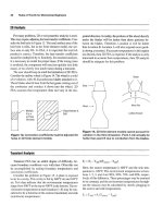
Friction Factor and Darcy Equation
The pipe flow equation most commonly used is the
Darcy-Weisbach equation that prescribes the head loss hf
to be:
tion chart is probably the most convenient method of getting the value of f (see Figure 1). For laminar pipe flows
(Reynolds number R less than 2,000), f = -,
64 because
R
L
V
hf=f-D 2g
where L is the pipe length, D is the internal pipe diameter,
V is the average fluid velocity, and f is the Moody friction
factor (nondimensional) which is a function of several
nondimensional quantities:
head loss in laminar flows is independent of wall roughness.
If the duct or pipe is not of circular cross-section, an
equivalent hydraulic diameter De,as defined earlier is
used in these calculations.
The Swamy and Jain empirical equation may be used to
calculate a pipe design diameterdirectly. The relationshipis:
f=f(y,E)
pVD E
where (pV D/jQ is the Reynolds number R,and E is the specific surface roughness of the pipe mterid.The Moody fiic-
Ix
Id
1x10'
l x l d
where E is in ft, Q is in cfs, L is in ft, v is in ft2/s, g is in
ft/s2, and hf is in f&.lb/lbunits.
IXloL
I x 107
ReynoMsNumba R
Figure 1. Friction factor vs. Reynolds number.
lxld
10
Rules of Thumb for Mechanical Engineers
~~
lasses in Pipe Fittings and Valves
In addition to losses due to friction in a piping system,
there are also losses associated with flow through valves and
fittings. These are called minor losses, but must be accounted for if the system has a lot of such fittings. These
are treated as equivalent frictional losses. The minor loss
may be treated either as a pressure drop Ap = -KpV2/2 or
as a head loss Ah = -KV2/(2g). The value of the loss coefficient K is obtained through experimental data. For
valves and fittings, manufacturers provide this value. It may
also be calculated from the equivalent length concept: K =
fLJD, where Le is the equivalent pipe length that has the
same frictional loss. Table 3 gives these values for some
common fittings.
For sudden enlargements in a pipe from diameter D1to
a larger diameter D2,
the K value is obtained from:
Table 3
K Values for Common Fittings
Type of Fitting
K
L$D
45-degree elbow
90-degree bend
Diaphragm valve, open
Diaphragm valve, half open
Diaphragm valve, X open
Gate valve, open
Gate valve, half open
Globe valve, wide open
Globe valve, half open
Tee junction
Union and coupling
Water meter
0.35
0.75
2.30
4.30
21.oo
0.1 7
4.50
6.40
9.50
1.oo
0.04
7.00
17
35
115
215
1050
9
225
320
475
50
2
350
K = [I - (D1/D2)2]2
For sudden contractions in the pipeline from a larger diameter D2to a smaller diameter D1, the value of the loss
coefficient is:
The above relations should serve as guidelines. Corrections should be made for enlargements and contractionsthat
are gradual. Use values of K for fittings whenever furnished by the manufacturer.
Pipes in Series
Pipes connected in tandem can be solved by a method of
equivalent lengths. This procedure lets us replace a series
pipe system by a single pipeline having the same discharge
and the same total head loss. As an example, if we have two
pipes in series and if we select the first section as reference,
then the equivalent length of the second pipe is obtained by:
[ ]
L2 = L, - D,
fi
f2
5
D,
The values of fi and f2 are approximated by selectinga discharge within the range intended for the two pipes.
Pioes in Parallel
A common way to increase capacity of an existing line is
to install a second one parallel to the first. The flow is divided
in a way such that the friction loss is the same in
(in E
ries pipes, these losses are cumulative),but the discharge is
cumulative. For an illustration of three pipes in parallel:
h,, = hf2 = h,, Pentry + Zenq
Y
Q=Qi+Qz+Q3
-
(?+ .-.)
(22)
(23)
where hmand zeitare elevations at the two points.
If dischargeQ is known, then the solution P d m Uses
this equal loss principle iteratively to find the solution
(flow distribution and head loss).
The pipe network system behaves in an analogous fashion to a DC electrical circuit, and can be solved in an analogous manner by those familiar with the electrical circuit
analysis.
Fluids
11
OPEN-CHANNEL FLOW
Study of open channels is important in the study of river
flow and irrigation canals. The mechanics of flow in open
channels is more complicated than that in pipes and ducts
because of the presence of a free surface. Unlike closed conduit flow, the specificroughessfactor E for open-channel
flows is dependent on the hydraulic state of the channel. The
flow is called uniform if the cross-section of the flow
doesn't vary along the flow direction. Most open-channel
flow situations are of turbulent nature. Therefore, a major
part of the empirical and semi-empirical study has been done
under the full turbulence assumption (Reynolds number R
greater than 2,000 to 3,000).
Frictionless Open-Channel Flow
Flow in Venturi Flume
In the case of flow in a Venturi flume (Figure 2), where
the width of the channel is deliberately changed to measure
Free Surface
P,
v
V1
4
the flow rate, we can obtain all relations by applying
Bernoulli's equation at the free surface, and the continuity
equation, which are:
Figure &Open-channel flow over a rise.
V:/2+gh,=V:/2+g
(h2 + S )
Q = Vlbhl = Vzbh,
--Q2
Q2
+(h2 + S )
2gb2h: - h1 2gb2h:
Figure 2. Flow in a Venturi flume.
V:/2
+ gh, = V:
12 + gh,
Note that the sum of the two terms h + Q2/(2gb2h2)is
called the specifichead, H. The critical specific head H,and
the critical depth h, can be found by taking the derivative
of above term and equating it to zero.
=($)
Q = Vlblh, = V2bzh2
h:
-Q2 -
H, = 3hJ2
2g
hl -h2
l/bihq - l/b:h:
Flow Over a Channel Rise
In the case of flow in a constant width (b) horizontal rectangular channel with a small rise on the floor (Figure 3),
the relations are:
Note that for a given specific head and flow rate, two different depths of h are possible. The Froude n d e r V/(gh)
specifies the flow characteristicsof the channel flow. If it is
less than unity, it is called subcritical, or tranquil, flow. If it
is more than unity, it is called supercritical, or rapid, flow.
12
Rules of Thumb for Mechanical Engineers
Flow Through a Siuice Gate
The maximum flow rate is given by:
In the case of flow generatedwhen a sluicegate that retains
water in areservoir is partiaUy raised (Figm 4), by combining
Bernoulli's equation and the continuity equation we get:
ho =- " + h
2gbzhz
I
////// //// # f / / / / / / / / / / / ~ / . r
FIgure 4. Flow through a sluice gate.
Here too, the Froude number is a measure of flow rate. Maximum flow rate is present when the Froude number is
unity. By raising the gate from its closed position, the flow
discharge is increased until a maximum discharge is obtained, and the depth downstream is two-thirds of the reservoir depth. If the gate is raised beyond this critical height,
the flow rate actually drops.
The above analysis and observation is also true for flow
over the crest of a dam, and the same equation for max flow
rate is valid-where
is the water level in the reservoir
measured from the crest level, and h is the water level
above the crest.
~~
~
~
Laminar Open-Channel Flow
Considering the effects of viscosity, the steady laminar
flow down an inclined plane (angle a),the velocity distribution is given by:
where y is the distance from the bottom surface of the
channel (in a direction perpendicular to the flow dire0
tion). The volume flow per unit width (q) is given by:
u = - pg (2h - y) y sin a
2u
q = j o h u d y g= g h3 sina
Tbrbulent Open-Channel Flow
The wall shear stress T, due to friction in a steady, uniform, one-dimensional open-channel flow is given by:
where A is the cross-sectional area of the channel, P is the
wetted perimeter, and a is the downward sloping angle.
T
, = pg (sin a)A P
Hydraulic Jump
When a rapidly flowing fluid suddenly comes across a
slowly flowing channel of a larger cross-sectional area,there
is a suddenjump in elevation of the liquid surface. This hap
pens because of conversion of kinetic energy to potential
energy, the transition being quite turbulent. This phenomenon of steady nonuniformflow is called the hydraulicjump.
By applying the continuity and momentum equations, the
increased depth y2 can be expressed as:
Y1
+/yl
y, = - 2
-+ -
Fluids
The subscripts 1 and 2 represent flow conditions before
and after the hydraulic jump. Through the energy equation,
the losses due to this hydraulic jump as represented by hiump
can be found:
This phenomenon is often used at the bottom of a spillway
to diffuse most of the fluid kinetic energy, and also as an
13
effective way of mixing in a mixing chamber.
The Froude numbers F1and F2for a rectangular channel section before and after the jump are related by:
where the dimensionless Froude number F = V l c y . The
Froude number before the jump is greater than 1, and is less
than 1 after the jump.
FLUID MEASUREMENTS
Total energy in a fluid flow consists of pressure head, velocity head, and potential head
H = -P+ - +v2
z
P
The gravitational head is negligible; hence, if we know two
of the three remaining variables (H, p, and V), we can find
the other. In addition to the above, flow measurement also
involves flow discharge, turbulence, and viscosity.
2g
Pressure and Velocity Measurements
Stutic pressure is measured by either a piezometer opening or a static tube (Figure 5 [a]). The piezometer tap, a
smooth opening on the wall normal to the surface, can
measure the pressure head directly in feet of fluid hp = plp.
In the flow region away from the wall, the static tube probe
may be introduced, directed upstream with the end closed.
The static pressure tap must be located far enough downstream from the nose of the probe. The probe must also be
aligned parallel to the flow direction.
Stagnation pressure (or "total pressure") is measured by
a pitot tube pigure 5 [bl), an open-ended tube facing directly
into the flow, where the flow is brought to rest isentropically
(no loss). At this point of zero velocity, pt = p + pV2/2.Often,
both the static tube and the pitot tube are combined to make
one "pitot-static" probe (Figure 5 [c]), which will in effect
measure velocity of the flow. The two ends are connected
to a manometer whose fluid has a specific gravity So. By applying Bernoulli's equation between the two points:
v = JM
= J2gAh (So - S)/S
-- / 1 k c
v
+II
S
pressure p
x
+
SO
(a) Static tube and piezometer
(b) Pitot tube
total
pressure pt
(c) Pitot-static tube
Figure 5. Pressure and velocity measurements.
14
Rules of Thumb for Mechanical Engineers
If the pitot probe is used in subsonic compressibleflow, the
compressibleform of the stagnationpressure should be used:
( ;1
p t = p 1+-y
By knowing the stagnation and static pressures, and
also the static temperature, the mach number at that point
can also be found:
q ' ( y - 1 )
M = Via =
VI^
Rate Measurement
Flow rate in a Venturi meter (Figure 6 [a]) is given by:
Flow rate in an orifice meter (Figure 6 [c]) is given by:
Flow rate in a flow nozzle (Figure 6 p]>
is given by:
where e,, C,, and C,are the corresponding discharge coefficients for the three types of meters, and are functions
of the Reynolds number. These are obtained through experimental tests.
r
-
(a) Venturi meter
(b) Flow nozzle
(c) Orifice Meter
Figure 6. Flow measurement devices.
~
Hot-wire and Thin-Film Anemometry
Air velocities may be measured by vane anemometers
where the vanes drive generators that directly indicate the air
velocity. They can be made very sensitive to extremely low
air currents. Gas velocities may be measured with hot-wire
anemometers.The principle of operation of these devices is
the fact that the resistance to flow of electricity through a thin
platinum wire is a function of cooling due to air around it.
%ire
= Rref [ I +
I2 Rwire
a (Twire - TreAl
= hA (Twire - Tfluid)
where h is the convective heat transfer coefficient between
wire and gas, A is wire surface area, I is the current in amperes, R is resistance of the wire, and T is temperature.
The same principle is applied in hot-film anemometers
to measure liquid velocities. Here the probe is coated with
a thin metallic film that provides the resistance. The film
is usually coated with a very thin layer of insulating material to increase the durability and other problems associated with local boiling of the liquid.