31 1500 9070 e 2004 01
Bạn đang xem bản rút gọn của tài liệu. Xem và tải ngay bản đầy đủ của tài liệu tại đây (208.53 KB, 3 trang )
DRAWING/DOCUMENT STATUS
A
FOR REFERENCE
2006-04-10
First issue
Steenmeyer
DATE
DESCRIPTION
Bearb.
Coord.
Rev.
Liedtke
Sudhoff
Geprüft
Checked
APPD.
PROJECT :
CAMAU 1 750MW COMBINED CYCLE POWER PLANT
OWNER :
OWNER’S ENGINEER :
PETRO VIETNAM
CPMB
CONTRACTOR :
CONTRACTOR’S ENGINEER :
LILAMA CORPORATION
FICHTNER
SUBCONTRACTOR’S NAME :
SUBCONTRACTOR’S SUPPLIER :
s
PARKER
POWER GENERATION
DRAWING TITLE :
System Description Hydraulic Clearance Optimization
PKZ
UAS
Contents Code
Ursprung/Original
Reg. No.
UNID
Urspr.-PKZ-Nr.
Orig.-PC
Ursprung-Nr./Original-No.
Projekt/Project
gezeich.
Drawn
bearb.
Coord.
geprüft
Checked
Abtlg.
Dept.
PKZ/PC
Datum
Date
Name
06-04-10
STEENM
06-04-10
LIEDTKE
06-04-10
SUDHOFF
P415
sgd.
s AG
POWER GENERATION
CA MAU 1 CCPP
VIT154
Maßstab
Scale
UA/DCC
Type
Inhaltskennzeichen
Contents Code
N/A
A4
Benennung/Title
System Description Hydraulic
Clearance Optimization
Dienstst./Dept.
P415
UNID
423216989
XS00
MBX98
Zähl.-Nr.
Reg.-No.
Index/Rev.
355062
Version
A
Blatt-Nr./Page-No.
CM1-L1-M-MBX98.08-355062
Erstellt mit/designed with
Ersatz für
Supersedes
0 of 2
Gas Turbine
Description of Auxiliary Systems
Compressor and Turbine / GT Bearings
Hydraulic Clearance Optimization (HCO)
Furthermore, the flushing operation constitutes a function
test of the bladder accumulator and instrumentation.
Refer also to:
List of Control Settings (SREL):
List of Measuring Instruments
List of Electrical Loads
Equipment List
Gas Turbine Instrumentation
P+I Diagram Gas Turbine
P+I Diagram, Hydraulic
Clearance Optimization
Lube and Jacking Oil System
P+I Diagram, Lube and
Jacking Oil
3.1-0210
3.1-0220
3.1-0230
3.1-0240
3.1-1000
3.1-1010
3.1-1510
3.1-8000
3.1-8010
The reproduction, transmission or use of this document
or its content is not permitted without express written
authority. Offenders will be liable for damages. All rights,
including rights created by patent grant or registration of
a utility model or design, are reserved
Settings, limits and measuring ranges of the devices
referred to here are given in the List of Measuring
Instruments, Equipment List, and List of Control Settings
(SREL). This description only gives guideline values.
Function
An efficiency improvement and output increase can be
achieved if the GT rotor is shifted against the direction of
flow. This reduces clearances between the turbine blades
and casing, in the compressor the corresponding
clearances are increased. By virtue of the gas turbine’s
mechanical design the losses in the compressor caused by
this are lower than the improvements in the turbine.
This shifting operation may only be performed when the
GT has thoroughly warmed up. To achieve this, the design
of thrust bearing permits axial displacement when a
hydraulic system supplies fluid to corresponding cylinders;
axial stops limit rotor displacement in in the primary
displacement direction and in the secondary displacement
direction.
Class: RESTRICTED
The operating pressure of max. 180bar is generated by
a separate hydraulic supply system. Axial displacement
must be performed slowly to prevent excessive mechanical
loadings on the structural elements of the bearing. Defined
displacement times can only be achieved when the
hydraulic system is vented, for this reason the system must
be completely filled with hydraulic fluid (lube oil) the thrust
bearing for each displacement direction is provided with a
supply and a return line. To keep pump loadings at low
levels and prevent rapid fouling of the filter, the return line
is shut off so that oil cannot continuously ciruculate in the
hydraulic clearance optimization (HCO) system.
To permit replacement of hydraulic fluid and prevent
excessive warming, a flushing operation is performed
during operation of the GT to regularly replace hydraulic
fluid in the HCO thrust bearing that is activated at that time.
This also displaces any trapped air bubbles or solid
contamination caused by abrasion of the HCO piston seals.
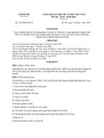
Configuration
The HCO supply unit comprises a base frame on which
two 100% pumps, a hydraulic bladder accumulator, and the
HCO control block and associated instrumentation are
mounted. The operating medium is lube oil taken from the
supply line of the lube oil system. Lube oil is returned from
this hydraulic system to the lube oil tank.
To achieve the requisite operating pressure on the
order
of
160
to
180bar,
two
gear
pumps
(MBA51AP001/002) are provided that are driven by AC
motors; these pumps are protected by a safety valve
(MBA51AA191). Other than during the pump test which is
performed once when the HCO system is started up, only
one pump is intermittently in operation to charge the
bladder accumulator MBA51BP001. A given pump can be
selected via the I&C system. Changeover to the other
pump is made in the event of a fault to the pump that is
selected. Each of these pumps is capable of maintaining
the operating pressure in the event of a loss of accumulator
function or failure of the HCO piston chamber return line
shutoff element.
To perform the principal task of permanently supplying
oil to the primary and secondary piston chambers of the
HCO thrust bearing, a bladder accumulator with
corresponding accumulator safety block MBA51AA193 is
provided on the HCO supply station. This accumulator is
charged by the above-mentioned pumps and can be
isolated from the system using shutoff valve MBA51AA255
and relieved via drain valve MBA51AA257.
A manually-actuated shutoff valve (MBA51AA251 and
MBA51AA252, respectively) is provided upstream of each
pump to permit inspection and maintenance work. Each of
these vavles is equipped with a position limit switch for
monitoring the valve setting OPEN. These pumps shall
only be started up when the corresponding valve is open.
To protect the flow control valves, oil is cleaned by filter
MBA51AT001 located downstream of the pumps. Filter
fouling is monitored by differential pressure switch
MBA51CP003. A pretrip alarm is annunciated if response
of this switch persists for longer than 5 seconds.
2/2-way solenoid-type seat valves (MBA53AA001 to
...006) are provided in the supply and return lines of the
primary and secondary displacement directions to enable
pressurizing and relieving of the primary and secondary
displacement direction pistons. The following flow control
valves are installed to ensure that the permissible axial
shaft displacement times are achieved: MBA53AA152 and
MBA53AA153 downstream of the solenoid valves in the
Siemens AG
Power Generation
3.1-1500-9070/1
MBA / MBD
0104E
Gas Turbine
Description of Auxiliary Systems
Compressor and Turbine / GT Bearings
Hydraulic Clearance Optimization (HCO)
chamber and MBA53CP103/104 in the return line from the
secondary displacement piston chamber. These pressure
sensors can be used to monitor pressure in the respective
piston chambers. In the interest of availability, these
pressure sensors are redundant.
supply line to the respective HCO piston chamber and
MBA54AA154 and MBA54AA155 upstream of the solenoid
valves in the return lines. Both the solenoid valves and the
control valves are located in a single overall control block
mounted on the supply station. Pressure limiting valves
MBA54AA151 and MBA54AA152 are provided to guard
against impermissible pressure increases in the piston
chambers of the HCO bearing; in the event of a fault these
valves route oil directly into the lube oil tank.
A sight glass (MBA51CF501) is installed in the common
return line of the HCO supply station that leads to the tank.
Position Transducers
The overall control block also includes the pressure
limiting valve (MBV53AA154) and the associated shutoff
valve (MBV53AA251), which are used during initial filling of
the system.
Two analog position transducers (MBA10CG101/102)
are installed on the compressor bearing cover. These
transducders permit detection of the (axial) rotor shaft
position and measurement of the displacement of the shaft
caused by the HCO system. In the interest of availability,
redundant transducers are provided. These position
transducers are not depicted in the P+ID of the hydraulic
clearance optimization system supply station.
The reproduction, transmission or use of this document
or its content is not permitted without express written
authority. Offenders will be liable for damages. All rights,
including rights created by patent grant or registration of
a utility model or design, are reserved
Pressure transducers MBA51CP101 und MBA51CP102
are used to register HCO system pressure in the common
line upstream of the solenoid valves. In the interest of
availability, these are redundant. Pressure gauge
MBA51CP501 is provided for checking system pressure
locally.
Pressure transducers MBA53CP101/102 are located in
the return line from the primary displacement piston
1
Sub-distribution
6
Motor and pump
2
Pressure transducer Pressure gauge
7
Pressure transducer
Class: RESTRICTED
3. Base frame
4
HCO control block
5
Bladder accumulator
Fig 1 + 2: HCO supply unit comprises
Siemens AG
Power Generation
3.1-1500-9070/2
MBA / MBD
0104E