Cach dat cam bien rung
Bạn đang xem bản rút gọn của tài liệu. Xem và tải ngay bản đầy đủ của tài liệu tại đây (2.67 MB, 2 trang )
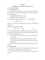
Sensor Placement and Orientation
Sensor Location Numbering
Mounting Options
Magnetic
Stud
1
Top/Bottom
Adhesive
Side
2
Sensor locations follow the
flow of energy.
3
Vertical Motor Mount
End
End
Measurement Tips
• If the driving motor has >40 HP (30 kW) and is >40 inches (102 cm), take
two measurements from each component in the drive train. If not, one
measurement per component is sufficient.
Front/Back
• Place the triaxial Sensor on a solid metal surface (not fan shrouds or cooling
fins) as close to the machine bearings as possible. Use the same locations
and Sensor orientations over time to ensure consistent diagnoses.
Quick
Reference
Guide
Side
• Attach the Sensor to a clean, flat, bare metal surface if possible.
• Sensor cable position should be parallel or perpendicular to the drive shaft
whenever possible.
• Hold the Sensor firmly and carefully roll the Sensor onto the test surface to
minimize the potential for impact.
A = Axial
Severity Scale
R = Radial
T = Tangential
KW = Other than US
Slight
HP = US
Moderate
Measurement Locations
RPM
No repair action is recommended. Retest the machine and
monitor the condition after maintenance.
(Months, even up to a year) – No immediate repair action is
required. Increase the frequency of measurements and monitor
the condition of the machine.
Serious
(Weeks) – Take maintenance action during the next planned
downtime or maintenance period.
Extreme
(Days) – Immediate action is required. Consider shutting down
the equipment and taking repair action now to avoid failure.
Bearing Type
Hz
PN 3464999 January 2010, Rev. 1, 4/10 © 2010 Fluke Corporation. All rights reserved. Printed in USA.
Motor Input (Driver)
Transmission
Coupled Motors
Centrifugal Pumps
Belt/Chain Driven Machines
Yes
Is Motor >40 HP (30 kW)?
No
Locate Sensor on each pillow block fan bearing or
bearing housing (pump) at 3 and 4.
2
1
2 A
2 B
Typical Belt-Driven
Horizontal Fan
Place at 2 if possible.
Place at 1 and 2 if possible.
1
Driven Components
Typical Belt-Driven
Pump
2
Note: Threaded rod or
welded struts holding the
motor and fan should extend
to ducting. Place the Sensor
on the structural rods or
struts.
Typical Axial Flow Fan
2 A
1 A
Locate Sensor at 4.
Fans
Typical Gland Exhaust Fan
Typical Horizontal Pump
Yes
Pump running >2000 GPM?
No
Locate Sensor at 3.
Typical fan with pedestal bearings
Preferred location at 3 and 4
Preferred locations at 3 and 4
Note: If top of housing is
inaccessible, select position
on the side of housing.
Note: Greater vibration isolation due
to longer shaft and pedestal bearings
requires measurement at both fan
bearing locations.
Locate Sensor at 4.
Locate Sensor at 4.
2 B
1 B
1 A
Typical Vertical Pump
• If locations 1 or 2 are not available, move the Sensor
down the side 90 ° from the top of the motor to 1A
and 2A.
Yes
• If 1A or 2A is not available, move the Sensor to the
end of the motor to 1B or 2B if possible.
Gearbox
Motor Close-Coupled Pumps and Fans
Yes
Measure 1 and 2
Is Motor >40 HP (30 kW)?
No
Pump running >3000 GPM?
No
Safety cover in place over
pillow block bearings?
Locate Sensor at 3.
Locate Sensor at 4.
Locate Sensor at 4.
Note: If pump free end
thrust bearing at 4 is difficult
to access or covered in
system fluid, locate Sensor
at 3.
Double-Reduction Gear
Internal View
Preferred locations:
Measure 2 only
If 2 is not available, move Sensor down the side of
the motor to 2A.
• 1st bearing on the input
shaft, preferably thrust
bearing at 3.
• Last bearing on the output
shaft at 5.
Typical ventilation fan / forced shaft blower
Overhung Coupled Pumps - Horizontal
Yes
Yes
No
Preferred location: top of each
pillow block at 3 and 4.
Underside of plate that bearings
are bolted to accessible?
No
Remove safety cover
and measure on pillow
blocks at 3 and 4.
Locate sensor
underneath plate directly
under bearings and
between mounting bolts
at 3A and 4A.
Preferred pump locations:
• Place the Sensor as close to the
bearing as possible, preferrably on
top at 3 and 4.
• If 3 is not accessible, then measure
at 4.
Compressor Single Stage (Screw)
Preferred locations at 3 and
4 are at the top of the drive
shaft (male screw) as close
to the bearings as possible.
1
2
3
4