API standard 670 machinery protection systems 4th
Bạn đang xem bản rút gọn của tài liệu. Xem và tải ngay bản đầy đủ của tài liệu tại đây (893.83 KB, 100 trang )
Machinery Protection
Systems
API STANDARD 670
FOURTH EDITION, DECEMBER 2000
COPYRIGHT American Petroleum Institute
Licensed by Information Handling Services
COPYRIGHT American Petroleum Institute
Licensed by Information Handling Services
Machinery Protection
Systems
Downstream Segment
API STANDARD 670
FOURTH EDITION, DECEMBER 2000
COPYRIGHT American Petroleum Institute
Licensed by Information Handling Services
SPECIAL NOTES
API publications necessarily address problems of a general nature. With respect to particular circumstances, local, state, and federal laws and regulations should be reviewed.
API is not undertaking to meet the duties of employers, manufacturers, or suppliers to
warn and properly train and equip their employees, and others exposed, concerning health
and safety risks and precautions, nor undertaking their obligations under local, state, or federal laws.
Information concerning safety and health risks and proper precautions with respect to particular materials and conditions should be obtained from the employer, the manufacturer or
supplier of that material, or the material safety data sheet.
Nothing contained in any API publication is to be construed as granting any right, by
implication or otherwise, for the manufacture, sale, or use of any method, apparatus, or product covered by letters patent. Neither should anything contained in the publication be construed as insuring anyone against liability for infringement of letters patent.
Generally, API standards are reviewed and revised, reaffirmed, or withdrawn at least every
five years. Sometimes a one-time extension of up to two years will be added to this review
cycle. This publication will no longer be in effect five years after its publication date as an
operative API standard or, where an extension has been granted, upon republication. Status
of the publication can be ascertained from the API Downstream Segment [telephone (202)
682-8000]. A catalog of API publications and materials is published annually and updated
quarterly by API, 1220 L Street, N.W., Washington, D.C. 20005.
This document was produced under API standardization procedures that ensure appropriate notification and participation in the developmental process and is designated as an API
standard. Questions concerning the interpretation of the content of this standard or comments and questions concerning the procedures under which this standard was developed
should be directed in writing to the standardization manager, American Petroleum Institute,
1220 L Street, N.W., Washington, D.C. 20005. Requests for permission to reproduce or
translate all or any part of the material published herein should also be addressed to the standardization manager.
API standards are published to facilitate the broad availability of proven, sound engineering and operating practices. These standards are not intended to obviate the need for applying sound engineering judgment regarding when and where these standards should be
utilized. The formulation and publication of API standards is not intended in any way to
inhibit anyone from using any other practices.
Any manufacturer marking equipment or materials in conformance with the marking
requirements of an API standard is solely responsible for complying with all the applicable
requirements of that standard. API does not represent, warrant, or guarantee that such products do in fact conform to the applicable API standard.
All rights reserved. No part of this work may be reproduced, stored in a retrieval system, or
transmitted by any means, electronic, mechanical, photocopying, recording, or otherwise,
without prior written permission from the publisher. Contact the Publisher,
API Publishing Services, 1220 L Street, N.W., Washington, D.C. 20005.
Copyright © 2000 American Petroleum Institute
COPYRIGHT American Petroleum Institute
Licensed by Information Handling Services
FOREWORD
This standard is based on the accumulated knowledge and experience of manufacturers and
users of monitoring systems. The objective of the publication is to provide a purchase specification to facilitate the manufacture, procurement, installation, and testing of vibration, axial
position, and bearing temperature monitoring systems for petroleum, chemical, and gas
industry services.
The primary purpose of this standard is to establish minimum electromechanical requirements. This limitation in scope is one of charter as opposed to interest and concern. Energy
conservation is of concern and has become increasingly important in all aspects of equipment
design, application, and operation. Thus, innovative energy-conserving approaches should be
aggressively pursued by the manufacturer and the user during these steps. Alternative
approaches that may result in improved energy utilization should be thoroughly investigated
and brought forth. This is especially true of new equipment proposals, since the evaluation of
purchase options will be based increasingly on total life costs as opposed to acquisition cost
alone. Equipment manufacturers, in particular, are encouraged to suggest alternatives to those
specified when such approaches achieve improved energy effectiveness and reduced total life
costs without sacrifice of safety or reliability.
This standard requires the purchaser to specify certain details and features. Although it is
recognized that the purchaser may desire to modify, delete, or amplify sections of this standard, it is strongly recommended that such modifications, deletions, and amplifications be
made by supplementing this standard, rather than by rewriting or by incorporating sections
thereof into another complete standard.
API standards are published as an aid to procurement of standardized equipment and materials. These standards are not intended to inhibit purchasers or producers from purchasing or
producing products made to specifications other than those of API.
API publications may be used by anyone desiring to do so. Every effort has been made by
the Institute to assure the accuracy and reliability of the data contained in them; however, the
Institute makes no representation, warranty, or guarantee in connection with this publication
and hereby expressly disclaims any liability or responsibility for loss or damage resulting
from its use or for the violation of any federal, state, or municipal regulation with which this
publication may conflict.
Suggested revisions are invited and should be submitted to the standardization manager,
American Petroleum Institute, 1220 L Street, N.W., Washington, D.C. 20005.
iii
COPYRIGHT American Petroleum Institute
Licensed by Information Handling Services
IMPORTANT INFORMATION CONCERNING USE OF ASBESTOS
OR ALTERNATIVE MATERIALS
Asbestos is specified or referenced for certain components of the equipment described in
some API standards. It has been of extreme usefulness in minimizing fire hazards associated
with petroleum processing. It has also been a universal sealing material, compatible with
most refining fluid services.
Certain serious adverse health effects are associated with asbestos, among them the
serious and often fatal diseases of lung cancer, asbestosis, and mesothelioma (a cancer of
the chest and abdominal linings). The degree of exposure to asbestos varies with the product and the work practices involved.
Consult the most recent edition of the Occupational Safety and Health Administration
(OSHA), U.S. Department of Labor, Occupational Safety and Health Standard for Asbestos,
Tremolite, Anthophyllite, and Actinolite, 29 Code of Federal Regulations Section
1910.1001; the U.S. Environmental Protection Agency, National Emission Standard for
Asbestos, 40 Code of Federal Regulations Sections 61.140 through 61.156; and the U.S.
Environmental Protection Agency (EPA) rule on labeling requirements and phased banning
of asbestos products (Sections 763.160-179).
There are currently in use and under development a number of substitute materials to
replace asbestos in certain applications. Manufacturers and users are encouraged to develop
and use effective substitute materials that can meet the specifications for, and operating
requirements of, the equipment to which they would apply.
SAFETY AND HEALTH INFORMATION WITH RESPECT TO PARTICULAR
PRODUCTS OR MATERIALS CAN BE OBTAINED FROM THE EMPLOYER, THE
MANUFACTURER OR SUPPLIER OF THAT PRODUCT OR MATERIAL, OR THE
MATERIAL SAFETY DATA SHEET.
iv
COPYRIGHT American Petroleum Institute
Licensed by Information Handling Services
CONTENTS
Page
1
GENERAL. . . . . . . . . . . . . . . . . . . . . . . . . . . . . . . . . . . . . . . . . . . . . . . . . . . . . . . . . . . .
1.1 Scope . . . . . . . . . . . . . . . . . . . . . . . . . . . . . . . . . . . . . . . . . . . . . . . . . . . . . . . . . . .
1.2 Alternative Designs . . . . . . . . . . . . . . . . . . . . . . . . . . . . . . . . . . . . . . . . . . . . . . . .
1.3 Conflicting Requirements . . . . . . . . . . . . . . . . . . . . . . . . . . . . . . . . . . . . . . . . . . .
2
REFERENCES . . . . . . . . . . . . . . . . . . . . . . . . . . . . . . . . . . . . . . . . . . . . . . . . . . . . . . . . 1
3
DEFINITIONS. . . . . . . . . . . . . . . . . . . . . . . . . . . . . . . . . . . . . . . . . . . . . . . . . . . . . . . . . 2
4
GENERAL DESIGN SPECIFICATIONS . . . . . . . . . . . . . . . . . . . . . . . . . . . . . . . . . . .
4.1 Component Temperature Ranges . . . . . . . . . . . . . . . . . . . . . . . . . . . . . . . . . . . . .
4.2 Humidity . . . . . . . . . . . . . . . . . . . . . . . . . . . . . . . . . . . . . . . . . . . . . . . . . . . . . . . .
4.3 Shock . . . . . . . . . . . . . . . . . . . . . . . . . . . . . . . . . . . . . . . . . . . . . . . . . . . . . . . . . . .
4.4 Chemical Resistance . . . . . . . . . . . . . . . . . . . . . . . . . . . . . . . . . . . . . . . . . . . . . . .
4.5 Accuracy . . . . . . . . . . . . . . . . . . . . . . . . . . . . . . . . . . . . . . . . . . . . . . . . . . . . . . . .
4.6 Interchangeability . . . . . . . . . . . . . . . . . . . . . . . . . . . . . . . . . . . . . . . . . . . . . . . . .
4.7 Scope of Supply and Responsibility . . . . . . . . . . . . . . . . . . . . . . . . . . . . . . . . . . .
5
CONVENTIONAL HARDWARE. . . . . . . . . . . . . . . . . . . . . . . . . . . . . . . . . . . . . . . . . 9
5.1 Radial Shaft Vibration, Axial Position, Phase Reference, Speed Sensing,
and Piston Rod Drop Transducers . . . . . . . . . . . . . . . . . . . . . . . . . . . . . . . . . . . . . 9
5.2 Accelerometer-Based Casing Transducers . . . . . . . . . . . . . . . . . . . . . . . . . . . . . 14
5.3 Temperature Sensors . . . . . . . . . . . . . . . . . . . . . . . . . . . . . . . . . . . . . . . . . . . . . . 14
5.4 Monitor Systems . . . . . . . . . . . . . . . . . . . . . . . . . . . . . . . . . . . . . . . . . . . . . . . . . 15
5.5 Wiring and Conduits . . . . . . . . . . . . . . . . . . . . . . . . . . . . . . . . . . . . . . . . . . . . . . 23
5.6 Grounding . . . . . . . . . . . . . . . . . . . . . . . . . . . . . . . . . . . . . . . . . . . . . . . . . . . . . . 26
5.7 Field-Installed Instruments . . . . . . . . . . . . . . . . . . . . . . . . . . . . . . . . . . . . . . . . . 26
6
TRANSDUCER AND SENSOR ARRANGEMENTS . . . . . . . . . . . . . . . . . . . . . . . .
6.1 Location and Orientation . . . . . . . . . . . . . . . . . . . . . . . . . . . . . . . . . . . . . . . . . . .
6.2 Mounting . . . . . . . . . . . . . . . . . . . . . . . . . . . . . . . . . . . . . . . . . . . . . . . . . . . . . . .
6.3 Identification of Transducers and Temperature Sensors . . . . . . . . . . . . . . . . . . .
28
28
34
36
7
INSPECTION, TESTING, AND PREPARATION FOR SHIPMENT . . . . . . . . . . .
7.1 General . . . . . . . . . . . . . . . . . . . . . . . . . . . . . . . . . . . . . . . . . . . . . . . . . . . . . . . . .
7.2 Inspection . . . . . . . . . . . . . . . . . . . . . . . . . . . . . . . . . . . . . . . . . . . . . . . . . . . . . . .
7.3 Testing . . . . . . . . . . . . . . . . . . . . . . . . . . . . . . . . . . . . . . . . . . . . . . . . . . . . . . . . .
7.4 Preparation for Shipment. . . . . . . . . . . . . . . . . . . . . . . . . . . . . . . . . . . . . . . . . . .
7.5 Mechanical Running Test . . . . . . . . . . . . . . . . . . . . . . . . . . . . . . . . . . . . . . . . . .
7.6 Field Testing. . . . . . . . . . . . . . . . . . . . . . . . . . . . . . . . . . . . . . . . . . . . . . . . . . . . .
36
36
37
37
37
37
38
8
VENDOR’S DATA. . . . . . . . . . . . . . . . . . . . . . . . . . . . . . . . . . . . . . . . . . . . . . . . . . . .
8.1 General . . . . . . . . . . . . . . . . . . . . . . . . . . . . . . . . . . . . . . . . . . . . . . . . . . . . . . . . .
8.2 Proposals . . . . . . . . . . . . . . . . . . . . . . . . . . . . . . . . . . . . . . . . . . . . . . . . . . . . . . .
8.3 Contract Data . . . . . . . . . . . . . . . . . . . . . . . . . . . . . . . . . . . . . . . . . . . . . . . . . . . .
38
38
42
43
v
COPYRIGHT American Petroleum Institute
Licensed by Information Handling Services
1
1
1
1
6
6
6
7
7
7
9
9
Page
APPENDIX A
APPENDIX B
APPENDIX C
APPENDIX D
APPENDIX E
APPENDIX F
APPENDIX G
APPENDIX H
APPENDIX I
APPENDIX J
MACHINERY PROTECTION SYSTEM DATA SHEETS . . . . . . . . .
TYPICAL RESPONSIBILITY MATRIX WORKSHEET . . . . . . . . . .
ACCELEROMETER APPLICATION CONSIDERATIONS . . . . . . . .
SIGNAL CABLE . . . . . . . . . . . . . . . . . . . . . . . . . . . . . . . . . . . . . . . . . . .
GEARBOX CASING VIBRATION CONSIDERATIONS. . . . . . . . . .
FIELD TESTING AND DOCUMENTATION REQUIREMENTS . . .
CONTRACT DRAWING AND DATA REQUIREMENTS . . . . . . . . .
TYPICAL SYSTEM ARRANGEMENT PLANS . . . . . . . . . . . . . . . . .
SETPOINT MULTIPLIER CONSIDERATIONS . . . . . . . . . . . . . . . . .
ELECTRONIC OVERSPEED DETECTION SYSTEM
CONSIDERATIONS . . . . . . . . . . . . . . . . . . . . . . . . . . . . . . . . . . . . . . . .
45
53
55
59
61
63
67
71
79
83
Tables
1
2
3A
3B
D-1
F-1
Machinery Protection System Accuracy Requirements . . . . . . . . . . . . . . . . . . . . . . 8
Minimum Separation Between Installed Signal and Power Cables. . . . . . . . . . . . 24
Accelerometer Test Points (SI) . . . . . . . . . . . . . . . . . . . . . . . . . . . . . . . . . . . . . . . . 42
Accelerometer Test Points (Customary Units) . . . . . . . . . . . . . . . . . . . . . . . . . . . . 42
Color Coding for Single-Circuit Thermocouple Signal Cable. . . . . . . . . . . . . . . . 60
Tools and Instruments Needed to Calibrate and Test Machinery
Protection Systems . . . . . . . . . . . . . . . . . . . . . . . . . . . . . . . . . . . . . . . . . . . . . . . . . 63
F-2 Data, Drawing, and Test Worksheet . . . . . . . . . . . . . . . . . . . . . . . . . . . . . . . . . . . . 64
G-1 Typical Milestone Timeline. . . . . . . . . . . . . . . . . . . . . . . . . . . . . . . . . . . . . . . . . . . 67
G-2 Sample Distribution Record (Schedule) . . . . . . . . . . . . . . . . . . . . . . . . . . . . . . . . . 68
J-1 Recommended Dimensions for Speed Sensing Surface
When Magnetic Speed Sensors are Used . . . . . . . . . . . . . . . . . . . . . . . . . . . . . . . . 85
J-2 Recommended Dimensions for Non-Precision Speed Sensing Surface
When Proximity Probe Speed Sensors are Used . . . . . . . . . . . . . . . . . . . . . . . . . . 85
J-3 Recommended Dimensions for Precision-Machined Speed Sensing Surface
When Proximity Probe Speed Sensors are Used . . . . . . . . . . . . . . . . . . . . . . . . . . 85
Figures
1
2
3
4
5
6
7
8
9
10
11
12
13
14
15
16
17
18
19
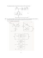
Machinery Protection System . . . . . . . . . . . . . . . . . . . . . . . . . . . . . . . . . . . . . . . . . . 4
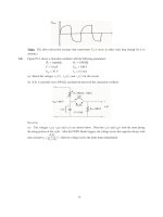
Standard Monitor System Nomenclature . . . . . . . . . . . . . . . . . . . . . . . . . . . . . . . . . 5
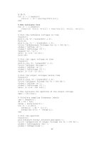
Transducer System Nomenclature . . . . . . . . . . . . . . . . . . . . . . . . . . . . . . . . . . . . . . 7
Typical Curves Showing Accuracy of Proximity Probe Channels. . . . . . . . . . . . . 10
Standard Probe and Extension Cable . . . . . . . . . . . . . . . . . . . . . . . . . . . . . . . . . . . 11
Standard Options for Proximity Probes and Extension Cables . . . . . . . . . . . . . . . 12
Standard Magnetic Speed Sensor With Removable (Non-Integral)
Cable and Connector . . . . . . . . . . . . . . . . . . . . . . . . . . . . . . . . . . . . . . . . . . . . . . . . 13
Piston Rod Drop Calculations. . . . . . . . . . . . . . . . . . . . . . . . . . . . . . . . . . . . . . . . . 19
Piston Rod Drop Measurement Using Phase Reference Transducer
For Triggered Mode . . . . . . . . . . . . . . . . . . . . . . . . . . . . . . . . . . . . . . . . . . . . . . . . 20
Typical Standard Conduit Arrangement . . . . . . . . . . . . . . . . . . . . . . . . . . . . . . . . . 24
Typical Standard Armored Cable Arrangement . . . . . . . . . . . . . . . . . . . . . . . . . . . 25
Inverted Gooseneck Trap Conduit Arrangement . . . . . . . . . . . . . . . . . . . . . . . . . . 26
System Grounding (Typical). . . . . . . . . . . . . . . . . . . . . . . . . . . . . . . . . . . . . . . . . . 27
Standard Axial Position Probe Arrangement . . . . . . . . . . . . . . . . . . . . . . . . . . . . . 29
Typical Piston Rod Drop Probe Arrangement . . . . . . . . . . . . . . . . . . . . . . . . . . . . 31
Typical Installations of Radial Bearing Temperature Sensors . . . . . . . . . . . . . . . . 33
Typical Installations of Radial Bearing Temperature Sensors . . . . . . . . . . . . . . . . 34
Typical Installation of Thrust Bearing Temperature Sensors . . . . . . . . . . . . . . . . . 35
Calibration of Radial Monitor and Setpoints for Alarm and Shutdown . . . . . . . . 39
vi
COPYRIGHT American Petroleum Institute
Licensed by Information Handling Services
Page
20
21
C-1
C-2
C-3
H-1
H-2
H-3
H-4
H-5
H-6
I-1
J-1
J-2
J-4
Calibration of Axial Position (Thrust) Monitor . . . . . . . . . . . . . . . . . . . . . . . . . . .
Typical Field Calibration Graph for Radial Vibration and Axial Position. . . . . . .
Typical Flush Mounted Accelerometer Details . . . . . . . . . . . . . . . . . . . . . . . . . . .
Typical Non-Flush Mounted Arrangement Details for Integral-Stud
Accelerometer . . . . . . . . . . . . . . . . . . . . . . . . . . . . . . . . . . . . . . . . . . . . . . . . . . . . .
Typical Non-Flush Mounting Arrangement for Integral-Stud
Accelerometer and Armored Extension Cable . . . . . . . . . . . . . . . . . . . . . . . . . . . .
Typical System Arrangement for a Turbine With Hydrodynamic Bearings . . . . .
Typical System Arrangement for a Double-Helical Gear . . . . . . . . . . . . . . . . . . .
Typical System Arrangement for a Centrifugal Compressor
or a Pump With Hydrodynamic Bearings. . . . . . . . . . . . . . . . . . . . . . . . . . . . . . . .
Typical System Arrangement for an Electric Motor With Sleeve Bearings. . . . . .
Typical System Arrangement for a Pump or Motor With Rolling
Element Bearings . . . . . . . . . . . . . . . . . . . . . . . . . . . . . . . . . . . . . . . . . . . . . . . . . .
Typical System Arrangement for a Reciprocating Compressor. . . . . . . . . . . . . . .
Setpoint Multiplication Example . . . . . . . . . . . . . . . . . . . . . . . . . . . . . . . . . . . . . .
Overspeed Protection System . . . . . . . . . . . . . . . . . . . . . . . . . . . . . . . . . . . . . . . . .
Relevant Dimensions for Overspeed Sensor and Multi-Tooth Speed
Sensing Surface Application Considerations . . . . . . . . . . . . . . . . . . . . . . . . . . . . .
Precision-Machined Overspeed Sensing Surface. . . . . . . . . . . . . . . . . . . . . . . . . .
vii
COPYRIGHT American Petroleum Institute
Licensed by Information Handling Services
40
41
56
57
57
72
73
74
75
76
77
80
83
84
86
COPYRIGHT American Petroleum Institute
Licensed by Information Handling Services
Machinery Protection Systems
ASME2
Y14.2M
PTC 20.2-1965
1 General
1.1 SCOPE
This standard covers the minimum requirements for a
machinery protection system measuring radial shaft vibration, casing vibration, shaft axial position, shaft rotational
speed, piston rod drop, phase reference, overspeed, and critical machinery temperatures (such as bearing metal and
motor windings). It covers requirements for hardware
(transducer and monitor systems), installation, documentation, and testing.
CENELEC3
EN50082-2
DIN4
EN 50022
Note: A bullet (•) at the beginning of a paragraph indicates that
either a decision is required or further information is to be provided
by the purchaser. This information should be indicated on the
datasheets (see Appendix A); otherwise, it should be stated in the
quotation request or in the order.
IEC5
584-1
1.2 ALTERNATIVE DESIGNS
The machinery protection system vendor may offer alternative designs. Equivalent metric dimensions and fasteners
may be substituted as mutually agreed upon by the purchaser
and the vendor.
IPCEA6
S-61-402
1.3 CONFLICTING REQUIREMENTS
ISA7
S12.1
In case of conflict between this standard and the inquiry or
order, the information included in the order shall govern.
S12.4
2 References
S84.01
2.1 The editions of the following standards, codes, and
specifications that are in effect at the time of publication of
this standard shall, to the extent specified herein, form a part
of this standard. The applicability of changes in standards,
codes, and specifications that occur after the inquiry shall be
mutually agreed upon by the purchaser and the machinery
protection system vendor.
API
RP 552
RP 554
Std 610
Std 612
ANSI1
MC96.1
Electromagnetic Compatibility Generic
Immunity Standard. Part 2: Industrial
Environment
Low voltage switchgear and controlgear for industrial use; mounting
rails, top hat rails, 35 mm wide for
snap-on mounting of equipment.
Thermocouples,
Tables
Part
I:
Reference
Thermoplastic-Insulated Wire and Cable
for the Transmission and Distribution of
Electrical Energy
Definitions and Information Pertaining
to Electrical Instruments in Hazardous
(Classified) Locations
Instrument Purging for Reduction of
Hazardous Area Classification
Application of Safety Instrumented Systems for the Process Industries
Military Specifications8
MIL-C-39012-C Connectors, Coaxial, Radio Frequency,
General Specification for
MIL-C-39012/5F Connectors, Plug, Electrical, Coaxial,
Radio Frequency, [Series N (Cabled)
Right Angle, Pin Contact, Class 2]
Signal Transmission Systems
Process Instrumentation and Control, Section 3, Alarm and Protective Devices
Centrifugal Pumps for Petroleum, Heavy
Duty Chemical and Gas Industry Services
Special Purpose Steam Turbines for Petroleum, Chemical, and Gas Industry Services
2American Society of Mechanical Engineers, 22 Law Drive, Box
2300, Fairfield, New Jersey 07007-2300.
3European Committee for Electrotechnical Standardization, Rue de
Stassart, 35, B - 1050 Brussels.
4Deutsches Institut Fuer Normung e.V., Burggrafenstrasse 6, Postfach 11 07, 10787 Berlin, Germany.
5International Electrotechnical Commission, 1 Rue de Varembe,
Geneva, Switzerland.
6Insulated Power Cable Engineers Association, 283 Valley Road,
Montclair, New Jersey 07042.
7Instrument Society of America, P.O. Box 12277, Research Triangle
Park, North Carolina 27709.
8Available from Naval Publications and Forms Center, 5801 Tabor
Avenue, Philadelphia, Pennsylvania 19120.
Temperature Measurement Thermocouples
1American National Standards Institute, 11 West 42nd Street, New
York, New York 10036.
1
COPYRIGHT American Petroleum Institute
Licensed by Information Handling Services
Line Conventions and Lettering
Overspeed Trip Systems for Steam Turbine-Generator Units
2
API STANDARD 670
MIL-STD-883B Tests, Methods, and Procedures for
Micro-Electronics
NEMA9
250
WC 5
NFPA10
70
496
OSHA11
Form 20
Enclosures for Electrical Equipment
(1000 Volts Maximum)
Thermoplastic-Insulated Wire and Cable
for the Transmission and Distribution of
Electrical Energy
National Electrical Code
Purged and Pressurized Enclosures for
Electrical Equipment
Material Safety Data Sheet
Schneider Electric12
PI-MBUS-300
Modbus® Protocol Reference Guide
2.2 The standards, codes, and specifications of the American Iron and Steel Institute (AISI)13 also form part of this
standard.
2.3 The purchaser and the machinery protection system
vendor shall mutually determine the measures that must be
taken to comply with any governmental codes, regulations,
ordinances, or rules that are applicable to the equipment.
3 Definitions
Terms used in this standard are defined as follows:
3.1 accelerometer: A piezoelectric sensor containing integral amplification with an output proportional to acceleration.
3.2 accelerometer cable: An assembly consisting of a
specified length of cable and mating connectors. Both the
cable and the connectors must be compatible with the particular accelerometer and (when used) intermediate termination.
3.3 accuracy: The degree of conformity of an indicated
value to a recognized accepted standard value or ideal value.
3.4 active magnetic speed sensor: A magnetic speed
sensor that requires external power and provides a conditioned
9National Electrical Manufacturers Association, 2101 L Street,
N.W., Washington, D.C. 20037.
10National Fire Protection Association, 1 Batterymarch Park, P.O.
Box 9101, Quincy, Massachusetts 02269.
11Occupational Safety and Health Administration, U.S. Department
of Labor, The Code of Federal Regulations is available from the U.S.
Government Printing Office, Washington, D.C. 20402.
12Schneider Electric–Automation Business, 1 High Street, North
Andover, Massachusetts 01845-2699.
13American Iron and Steel Institute, 1101 17th Street, N.W., Washington, D.C. 20036-4700.
COPYRIGHT American Petroleum Institute
Licensed by Information Handling Services
(that is, square wave) output. Typical excitation is between +5
to +30 Vdc.
3.5 active (normal) thrust direction: The direction of a
rotor axial thrust load expected by the machinery vendor when
the machinery is operating under normal running conditions.
3.6 alarm (alert) setpoint: A preset value of a parameter
at which an alarm is activated to warn of a condition that
requires corrective action.
3.7 alarm/shutdown/integrity logic: The function of a
monitor system whereby the outputs of the signal processing
circuitry are compared against alarm or shutdown setpoints
and circuit fault criteria. Violations of these setpoints or circuit fault criteria result in alarm or shutdown status conditions
in the monitor system. These status conditions may be subjected to preset time delays or logical voting with other status
conditions, and are then used to drive the system output relays
and status indicators and outputs.
3.8 bench test: A factory acceptance test performed
within the testing range (see 4.1 and Table 1).
3.9 best fit straight line: The line drawn through the
actual calibration curve where the maximum plus or minus
deviations are minimized and made equal.
3.10 blind monitor system: Does not contain an integral
display. A blind monitor system is permitted as a “when specified” option of this standard provided it is supplied with at
least one dedicated, continuous, non-integral display. The
blind monitor provides certain minimal integral status indication independently of any non-integral displays (see 5.4.1.6.b).
3.11 buffered output: An unaltered, analog replica of the
transducer input signal that preserves amplitude, phase, frequency content, and signal polarity. It is designed to prevent a
short circuit of this output to monitor system ground from
affecting the operation of the machinery protection system.
The purpose of this output is to allow connection of vibration
analyzers, oscilloscopes, and other test instrumentation to the
transducer signals.
3.12 channel: The monitor system components associated with a single transducer. The number of channels in a
monitor system refers to the number of transducer systems it
can accept as inputs.
3.13 channel pair: Two associated measurement locations (such as the X and Y proximity probes at a particular
radial bearing or the two axial proximity probes at a particular
thrust bearing).
3.14 circuit fault: A machinery protection system circuit
failure that adversely affects the function of the system.
MACHINERY PROTECTION SYSTEMS
3
3.15 construction agency: The contractor that installs
the machinery train or its associated machinery protection
system.
processing, and alarm/shutdown/integrity logic. Its function
is to continuously measure shaft rotational speed and activate
its output relays when an overspeed condition is detected.
3.16 contiguous: Mechanically connected and included
in the same housing or rack containing the signal processing
and alarm/shutdown/integrity logic functions of the monitor
system.
3.26 extension cable: The interconnection between the
proximity probe’s integral cable and its associated oscillatordemodulator.
Note: Installation of all monitor system components in the same
panel or cabinet is not the same as contiguous.
3.17 continuous display: Simultaneous, uninterrupted
indication of all status conditions and measured variables in
the machinery protection system as required by this standard.
It also continuously updates this indication at a rate meeting
or exceeding the requirements of this standard.
3.27 field changeable: Refers to a design feature of a
machinery protection system that permits alteration of a function after the system has been installed.
3.28 filter: An electrical device that attenuates signals outside the frequency range of interest.
3.29 g: A unit of acceleration equal to 9.81 meters per second squared (386.4 in. per second squared).
3.18 controlled access: A security feature of a machinery protection system that restricts alteration of a parameter to
authorized individuals. Access may be restricted by means
such as the use of a key or coded password or other procedures requiring specialized knowledge.
3.30 gauss level: The magnetic field level of a component. It is best measured with a Hall effect probe.
3.19 dedicated display: A display which indicates only
those parameters from its associated machinery protection
system(s) and is not shared with or used to indicate information from other systems such as process controllers, logic
controllers, turbine controllers, and so forth.
3.32 inches per second (ips): A unit of velocity equal
to 25.4 millimeters per second (1 in. per second).
3.20 display: An analog meter movement, cathode ray
tube, liquid crystal device, or other means for visually indicating the measured variables and status conditions from the
machinery protection system. A display may be further classified as integral or non-integral, dedicated or shared, continuous or non-continuous.
3.21 dual path: A configuration of the monitor system
such that the same transducer system is used as an input to
two separate channels in the monitor system, and different
signal processing (such as filtering or integration) is applied
to each channel.
Note: An example of this is a single casing vibration accelerometer
that is simultaneously processed in the monitor system to both acceleration and velocity for separate filtering, display, and alarming.
3.31 inactive (counter) thrust direction: The direction opposite the active thrust direction.
3.33 integral display: A display that is contiguous with
the other components comprising the monitor system.
3.34 linear frequency response range: The portion
of the transducer’s voltage output versus frequency curve,
between lower and upper frequency limits, where the
response is linear within a specified tolerance.
3.35 linear range: The portion of a transducer’s output
where the output versus input relationship is linear within a
specified tolerance.
3.36 local: Refers to a device’s location when mounted on
or near the equipment or console.
3.37 machine case: A driver (for example, electric
motor, turbine, or engine) or any one of its driven pieces of
equipment (for example, pump, compressor, gearbox, generator, fan). An individual component of a machinery train.
3.22 dual voting logic: A monitor feature whereby the
signals on two channels must both be in violation of their
respective setpoints to initiate a change in status (two-out-oftwo logic).
3.38 machinery protection system: Consists of the
transducer system, signal cables, the monitor system, all necessary housings and mounting fixtures, and documentation
(see Figure 1).
3.23 dynamic range: The usable range of amplitude of a
signal, usually expressed in decibels.
3.39 machinery protection system vendor: The
agency that designs, fabricates, and tests components of the
machinery protection system.
3.24 electrically isolated accelerometer: An accelerometer in which all signal connections are electrically insulated from the accelerometer case or base.
3.25 electronic overspeed detection system: Consists of speed sensors, power supplies, output relays, signal
COPYRIGHT American Petroleum Institute
Licensed by Information Handling Services
3.40 machinery train: The driver(s) and all of its associated driven pieces of equipment.
3.41 machinery vendor: The agency that designs, fabricates, and tests machines. The machinery vendor may
4
API STANDARD 670
Sensor
Proximity probes
RTDs
Thermocouples
Accelerometers
Magnetic speed sensors
Sensor leads
Extension cables
Accelerometer cables
Transducer
system
Signal conditioner
(where required)
Machinery
protection
system
Oscillator-Demodulator
Signal cable
Signal processing
Monitor
system
Alarm/Shutdown/
Integrity logic processing
Power supply(ies)
Display indication
Inputs/Outputs
Protective relays
Figure 1—Machinery Protection System
COPYRIGHT American Petroleum Institute
Licensed by Information Handling Services
Radial vibration
Axial position
Casing vibration
Temperature
Piston rod drop
Speed indication
Overspeed detection*
* See paragraph 5.4.8.2.
MACHINERY PROTECTION SYSTEMS
purchase the monitor system or transducer system, or both,
and may install the transducers or the sensors on machines.
3.42 magnetic speed sensor: Responds to changes in
magnetic field reluctance as the gap between the sensor and
its observed ferrous target (speed sensing surface) changes.
By choosing a proper speed sensing surface, the magnetic
speed sensor’s output will be proportional to the rotational
speed of the observed surface. Magnetic speed sensors may
be either passive (self-powered) or active (require external
power).
3.43 monitor system: Consists of signal processing,
alarm/shutdown/integrity logic processing, power supply(ies), display/indication, inputs/outputs, and protective
relays (see Figures 1 and 2).
3.44 non-integral display: A display that is not contiguous with the other components comprising the monitor
system.
3.45 oscillator-demodulator: A signal conditioning
device that sends a radio frequency signal to a proximity
probe, demodulates the probe output, and provides an output
signal suitable for input to the monitor system.
3.46 overspeed protection system: An electronic
overspeed detection system and all other components necessary to shut down the machine in the event of an overspeed
condition. It may include (but is not limited to) items such as
trip valves, solenoids, and interposing relays.
3.47 owner: The final recipient of the equipment (who
will operate the machinery and its associated machinery protection system) and may delegate another agent as the purchaser of the equipment.
5
3.50 phase reference transducer: A gap-to-voltage
device that consists of a proximity probe, an extension cable,
and an oscillator-demodulator and is used to sense a onceper-revolution mark.
3.51 piston rod drop: A measurement of the position of
the piston rod relative to the proximity probe mounting location(s) (typically oriented vertically at the pressure packing
box on horizontal cylinders).
Note: Piston rod drop is an indirect measurement of the piston rider
band wear on reciprocating machinery (typically addressed by API
618).
3.52 positive indication: An active (that is, requires
power for annunciation and changes state upon loss of power)
display under the annunciated condition. Examples include
an LED that is lighted under the annunciated condition or an
LCD that is darkened or colored under the annunciated condition.
3.53 primary probes: Those proximity probes installed
at preferred locations and used as the default inputs to the
monitor system.
3.54 proximity probe: A noncontacting sensor that consists of a tip, a probe body, an integral coaxial cable, and a
connector and is used to translate distance (gap) to voltage.
3.55 probe area: The area observed by the proximity
probe during measurement.
3.56 probe gap: The physical distance between the face
of a proximity probe tip and the observed surface. The distance can be expressed in terms of displacement (mils,
micrometers) or in terms of voltage (volts DC).
3.57 purchaser: The agency that buys the equipment.
3.48 passive magnetic speed sensor: A magnetic
speed sensor that does not require external power to provide
an output.
3.58 radial shaft vibration: The vibratory motion of the
machine shaft in a direction perpendicular to the shaft longitudinal axis.
3.49 peak-to-peak value (pp): The difference between
positive and negative extreme values of an electronic signal or
dynamic motion.
3.59 remote: Refers to the location of a device when
located away from the equipment or console, typically in a
control room.
Power
supply(ies)
Vibration
channel(s)
Thrust
channel(s)
Accelerometer
channel(s)
Piston
rod drop
channel(s)
Speed
indicating
channel(s)
Temperature
channel(s)
Figure 2—Standard Monitor System Nomenclature
COPYRIGHT American Petroleum Institute
Licensed by Information Handling Services
Electronic overspeed
detection monitor
Redundant
power
supplies
3 overspeed
sensing
channels
6
API STANDARD 670
3.60 resistance temperature detector (RTD): A temperature sensor that changes its resistance to electrical current
as its temperature changes.
3.61 root mean square (rms): The square root of the
mean of the sum of the squares of the sample values.
3.62 sensor: A device (such as a proximity probe or an
accelerometer) that detects the value of a physical quantity
and converts the measurement into a useful input for another
device.
3.63 shaft vibration or position transducer: A gapto-voltage device that consists of a proximity probe, an extension cable, and an oscillator-demodulator.
3.64 shutdown (danger) setpoint: A preset value of a
parameter at which automatic or manual shutdown of the
machine is required.
3.65 signal cable: The field wiring interconnection
between the transducer system and the monitor system.
Note: Signal cable is typically supplied by the construction agency.
3.66 signal processing: Transformation of the output
signal from the transducer system into the desired parameter(s) for indication and alarming. Signal processing for
vibration transducers may include, for example, peak-topeak, zero-to-peak, or rms amplitude detection; pulse counting; DC bias voltage detection; filtering and integration. The
output(s) from the signal processing circuitry are used as
inputs to the display/indication and alarm/shutdown/integrity
logic circuitry of a monitor system.
3.67 signal-to-noise ratio: The ratio of the power of the
signal conveying information to the power of the signal not
conveying information.
3.68 spare probes: Probes installed at alternate locations
to take the place of primary probes (without requiring
machine disassembly) in the event of primary probe failure.
3.69 speed sensing surface: A gear, toothed-wheel, or
other surface with uniformly-spaced discontinuities that
causes a change in gap between the speed sensing surface and
its associated speed sensor(s) as the shaft rotates.
3.70 speed sensor: A proximity probe or magnetic
speed sensor used to observe a speed sensing surface. It provides an electrical output proportional to the rotational speed
of the observed surface.
3.71 standard option: A generally available alternative
configuration that may be specified in lieu of the default configuration specified herein.
3.72 tachometer: A device for indicating shaft rotational
speed.
COPYRIGHT American Petroleum Institute
Licensed by Information Handling Services
3.73 temperature sensor: A thermocouple or resistance
temperature detector and its integral sensor lead.
3.74 thermocouple: A temperature sensor consisting of
two dissimilar metals so joined to produce different voltages
when their junction is at different temperatures.
3.75 transducer system: A proximity probe, accelerometer, or sensor; an extension or accelerometer cable; and
oscillator-demodulator (when required). The transducer system generates a signal that is proportional to the measured
variable (see Figure 3).
3.76 transverse sensitivity: An accelerometer’s
response to dynamic loads applied in a direction perpendicular to the principal axis. It is also sometimes called cross-axis
sensitivity.
3.77 unit responsibility: Refers to the responsibility for
coordinating the delivery and technical aspects of the equipment and all auxiliary systems included in the scope of the
order. The technical aspects to be considered include, but are
not limited to, such factors as the power requirements, speed,
rotation, general arrangement, couplings, dynamics, noise,
lubrication, sealing system, material test reports, instrumentation (such as the machinery protection system), piping, conformance to specifications and testing of components.
3.78 velocity transducer: A piezo-electric accelerometer with integral amplification and signal integration such that
its output is proportional to its vibratory velocity.
3.79 voted channel: A channel requiring confirmation
from one or more additional channels as a precondition for
alarm (alert) and shutdown (danger) relay actuation.
4 General Design Specifications
4.1 COMPONENT TEMPERATURE RANGES
Machinery Protection System components have two temperature ranges, testing range and operating range, over
which accuracy shall be measured and in which the system
components shall operate, as summarized in Table 1.
Note: The testing range is a range of temperatures in which normal
bench testing occurs. It allows verification of the accuracy and operation of transducer and monitor system components without the
need for special temperature- or humidity-controlled environments.
The operating range represents temperatures over which the transducer and monitor system components are expected to operate in
actual service conditions.
4.2 HUMIDITY
4.2.1 For transducer systems, the accuracy requirements of
Table 1 shall apply at levels of relative humidity up to 100%
condensing, non-submerged, with protection of connectors.
MACHINERY PROTECTION SYSTEMS
Mounting
stud
Probe tip
Body
Integral
cable
Thermocouple
Magnetic
speed
sensor
Accelerometer
Proximity
probe
Accelerometer
cable
7
Magnetic
speed sensor
cable
Resistance
temperature
detector
Sensor lead
Connector
Extension cable
Terminal
head
OscillatorDemodulator
Signal cable
(Shielded triad)
Signal cable
(Shielded triad)
Proximity Probes
Accelerometer
Radial vibration
Casing vibration
Axial position
Phase reference
Piston rod drop
Speed indication
Overspeed detection (when specified)
Signal cable
Magnetic Speed Sensor
Speed indication
Overspeed detection
(TC signal
cable)
Signal cable
Thermocouple and RTD Sensors
Bearing temperature
Motor winding temperature
Figure 3—Transducer System Nomenclature
4.2.2 For monitor system components, the accuracy
requirements of Table 1 shall apply at levels of relative
humidity up to 95% non-condensing.
4.3 SHOCK
Accelerometers shall be capable of surviving a mechanical
shock of 5,000 g, peak, without affecting the accuracy
requirements specified in Table 1.
4.4 CHEMICAL RESISTANCE
4.4.1 Probes, probe extension cables, and oscillatordemodulators shall be suitable for environments containing
hydrogen sulfide and ammonia.
●
4.4.2 It shall be the joint responsibility of the purchaser and
machinery protection system vendor to ensure that all of the
machinery protection system components are compatible
with other specified chemicals.
COPYRIGHT American Petroleum Institute
Licensed by Information Handling Services
4.5 ACCURACY
4.5.1 Accuracy of the transducer system and monitor system in the testing and operating temperature ranges shall be
as summarized in Table 1.
4.5.2 If monitor system components or transducer system
components will be used in applications exceeding the
requirements of Table 1, the machinery protection system
vendor shall supply documentation showing how the accuracy is affected or suggest alternative transducer and monitor
components suitable for the intended application.
Notes:
1. Some applications may require piston rod drop and axial position
measurements with measuring ranges greater than 2 millimeters (80
mils). Special transducer systems, such as those with 3.94 mV per
micrometer (100 mV per mil) scale factors, are required for these
applications, and are not covered by this standard.
8
API STANDARD 670
Table 1—Machinery Protection System Accuracy Requirements
Temperature
Components
Accuracy Requirements as a Function of Temperature
Outside Testing Range
but Within Operating Range
Testing Range
Operating Range
Within Testing Range
Proximity probes
0°C to 45°C
(32°F to 110°F)
–35°C to 120°C
(–30°F to 250°F)
Incremental Scale Factor1: ± 5%
of 7.87 mV/µm (200 mV/mil)
Incremental Scale Factor1: An
additional ±5% of the testing
range accuracy
Extension cables
0°C to 45°C
(32°F to 110°F)
–35°C to 65°C
(–30°F to 150°F)
Deviation from Straight Line2:
within ±25.4 µm (±1 mil) of the
best fit straight line at a slope of
7.87 mV/µm (200 mV/mil)
Deviation from Straight Line2:
within ±76 µm (±3 mils) of the
best fit straight line at a slope of
7.87 mV/µm (200 mV/mil)
Oscillator-demodulators
0°C to 45°C
(32°F to 110°F)
–35°C to 65°C
(–30°F to 150°F)
Minimum linear range: 2 mm (80
mils)
Minimum linear range: same as
for testing range
Accelerometers and accelerometer extension cables3
20°C to 30°C
(68°F to 86°F)
–55°C to 120°C
(–65°F to 250°F)
Principal Axis Sensitivity: 100
mV/g ±5%
Principal Axis Sensitivity: 100
mV/g ±20%
Amplitude Linearity: 1% from
0.1 g pk to 50 g’s pk4
Frequency Response5: ±3 dB
from 10 Hz to 10 kHz, referenced
to the actual measured principal
axis sensitivity6.
Temperature sensors and
leads
0°C to 45°C
(32°F to 110°F)
–35°C to 175°C
(–30°F to 350°F)
±2°C (±4°F) over a measurement
range from –20°C to 150°C (0°F
to 300°F)
±3.7°C (±7°F) over a measurement range from –20°C to 150°C
(0°F to 300°F)
±1% of full scale range for the
channel
Same as for testing range
Temperature
±1°C (±2°F)
Same as for testing range
Speed and Overspeed
±1% of alarm setpoint
Same as for testing range
Monitor system components for measuring:
Radial Vibration,
Axial Position,
Piston Rod Drop, and
Casing Vibration
0°C to 45°C
(32°F to 110°F)
–20°C to 65°C
(0°F to 150°F)
Notes:
1. The incremental scale factor (ISF) error is the maximum amount the scale factor varies from 7.87 mV per micrometer (200 mV per mil)
when measured at specified increments throughout the linear range. Measurements are usually taken at 250 µm (10 mil) increments. ISF
error is associated with errors in radial vibration readings.
2. The deviation from straight line (DSL) error is the maximum error (in mils) in the probe gap reading at a given voltage compared to
a 7.87 mV per micrometer (200 mV per mil) best fit straight line. DSL errors are associated with errors in axial position or probe gap
readings.
3. During the testing of the accelerometers, the parameter under test is the only parameter that is varied. All other parameters must remain
constant.
4. Conditions of test: at any one temperature within the Testing Range, at any single frequency that is not specified but is within the specified frequency range of the transducer.
5. Frequency Response testing conditions: at any one temperature within the Testing Range, at an excitation amplitude that is not specified
but is within the specified amplitude range of the transducer.
6. Principal Axis Sensitivity testing conditions: (Testing Range) at any one temperature within the Testing Range, at 100 Hz, at an excitation amplitude that is not specified but is within the specified amplitude range of the transducer. (Operating Range) at any one temperature
within the Operating Range, at 100 Hz, at an excitation amplitude that is not specified but is within the specified amplitude range of the
transducer.
COPYRIGHT American Petroleum Institute
Licensed by Information Handling Services
MACHINERY PROTECTION SYSTEMS
4.7.2 The details of systems or components outside the
scope of this standard shall be mutually agreed upon by the
purchaser and machinery protection system vendor.
2. Aeroderivative gas turbines typically require special high-temperature transducer systems that exceed the operating range specified in
Table 1, and monitor systems with special filtering based on original
equipment manufacturer recommendations. Consult the machinery
protection system vendor.
5 Conventional Hardware
3. Radial vibration or position measurements using proximity probe
transducers on shaft diameters as small as 76 mm (3 in.) do not
introduce appreciable error compared to measurements made on a
flat target area. Shaft diameters smaller than this can be accommodated but generally result in a change in transducer scale factor. Consult the machinery protection system vendor.
5.1 RADIAL SHAFT VIBRATION, AXIAL POSITION,
PHASE REFERENCE, SPEED SENSING, AND
PISTON ROD DROP TRANSDUCERS
5.1.1 Proximity Probes
5.1.1.1 A proximity probe consists of a tip, a probe body,
an integral coaxial cable, and a connector as specified in
5.1.3, and shall be chemically resistant as specified in 4.4.
This assembly is illustrated in Figure 5.
4. Proximity probe measurements on shaft diameters smaller than 50
mm (2 in.) may require close spacing of radial vibration or axial
position transducers with the potential for their electromagnetic
emitted fields to interact with one another (cross-talk) resulting in
erroneous readings. Care should be taken to maintain minimum separation of transducer tips, generally at least 40 mm (1.6 in.) for axial
position measurements and 74 mm (2.9 in.) for radial vibration measurements.
5.1.1.2 Unless otherwise specified, the standard probe
shall have a tip diameter of 7.6 to 8.3 millimeters (0.300 to
0.327 in.), with a reverse mount, integral hex nut probe body
approximately 25 millimeters (1 in.) in length and 3/8-24UNF-2A threads.
4.5.3 The proximity probe transducer system accuracy
shall be verified on the actual probe target area or on a target
with the same electrical characteristics as those of the actual
probe target area (see Figure 4).
Notes:
1. Reverse mount probes are intended for use with probe holders
allowing external access to the probe and its integral cable. The use
of a reverse mount probe as the standard probe allows a single probe
configuration and thread length to be used throughout the entire
machine train. The length of the probe holder stem will typically
vary from one probe mounting location to the next, but this can be
trimmed in the field without the need to employ different probes.
4.5.4 When verifying the accuracy of any individual component of the proximity probe transducer system in the operating range, the components not under test shall be
maintained within the testing range.
4.6 INTERCHANGEABILITY
4.6.1 All components covered by this standard shall be
physically and electrically interchangeable within the accuracy specified in Table 1. This does not imply that interchangeability of components from different machinery
protection system vendors is required, or that oscillatordemodulators calibrated for different shaft materials are electrically interchangeable.
4.6.2 Unless otherwise specified, probes, cables, and oscillator-demodulators shall be supplied calibrated to the machinery protection system vendor’s standard reference target of
AISI Standard Type 4140 steel.
Note: Consult the machinery protection system vendor for a precision factory target when verifying the accuracy of the transducer
system to this standard. The machinery protection system vendor
should be consulted for applications using target materials other than
AISI Standard Type 4140 steel as they may require factory re-calibration of the transducer system.
4.7 SCOPE OF SUPPLY AND RESPONSIBILITY
4.7.1 For each train, the purchaser shall specify the agency
or agencies responsible for each function of the design, scope
of supply, installation, and performance of the monitoring
system (see Appendix B).
COPYRIGHT American Petroleum Institute
Licensed by Information Handling Services
9
2. Piston rod drop applications do not generally enable reverse
mount probes to be used. A standard option forward mount probe
should be selected instead.
●
5.1.1.3 When specified, the standard options may consist
of one or more of the following forward mount probe configurations (see Figure 6):
a. A tip diameter of 7.6 to 8.3 millimeters (0.300 to 0.327 in.)
and 3/8-24-UNF-2A English threads.
b. A tip diameter of 4.8 to 5.3 millimeters (0.190 to 0.208 in.)
and 1/4-28-UNF-2A English threads.
c. A tip diameter of 7.6 to 8.3 millimeters (0.300 to 0.327 in.)
and M10 x 1 metric threads.
d. A tip diameter of 4.8 to 5.33 millimeters (0.190 to 0.208
in.) and M8 x 1 metric threads.
e. Lengths other than approximately 25 millimeters (1 in.).
f. Flexible stainless steel armoring attached to the probe
body and extending to within 100 millimeters (4 in.) of the
connector.
5.1.1.4 The overall physical length of the probe and integral
cable assembly shall be approximately 1 meter (39 in.), measured from the probe tip to the end of the connector. The minimum overall physical length shall be 0.8 meters (31 in.); the
maximum overall physical length shall be 1.3 meters (51 in.).
10
API STANDARD 670
mils
µm
Channel Accuracy
Deviation from best–
fit straight line (DSL)
at a slope of
7.87 mV per micrometer
(200 mV per mil)
Channel Accuracy
Incremental scale factor (ISF)
Referenced to
7.87 mV per micrometer
(200 mV per mil)
Typical Gap-to-Voltage
transducing characteristic
Output (volts DC)
Gap (mils)
Gap (millimeters)
Note:
A – Maximum error during bench test within testing temperature range of 0°C TO 45°C (30°F TO 110°F).
B – Maximum error over operating temperature range.
Figure 4—Typical Curves Showing Accuracy of Proximity Probe Channels
COPYRIGHT American Petroleum Institute
Licensed by Information Handling Services
MACHINERY PROTECTION SYSTEMS
11
O-ring (optional)
Clear shrink
sleeve for field
identification
3/8 – 24 UNF – 2A
body
7/16 Hex
Probe cable
Probe 8.0 mm
tip
0.31 in.
Connector
15.3 mm
(0.60 in.)
35.0 mm
(1.38 in.)
1.0 m (39 in.)
STANDARD PROBE
Clear shrink
sleeve for field
identification
O-ring (optional)
Connector
1.0 m (39 in.)
4.0 m (158 in.)
STANDARD PROBE AND EXTENSION CABLE
Figure 5—Standard Probe and Extension Cable
COPYRIGHT American Petroleum Institute
Licensed by Information Handling Services
12
API STANDARD 670
Variable unthreaded
lengths
Jam nut
Forward mount proximity probe body
without integral hexnut
Flexible stainless steel armoring (optional)
Connector
Wrench flats standard for
forward mount probes.c
Proximity probe tip diameter and threads a
8.0 mm (0.31 in.) with 3/8 – 24 UNF 2A threads
8.0 mm (0.31 in.) with M10x1 metric threads;
5.0 mm (0.197 in.) with M8x1 metric threads; b
5.0 mm (0.197 in.) with 1/4 – 28 UNF 2A threads b
Notes:
a.
The standard option proximity probe may consist of one or more of the options
discussed in 5.1.1.3.
b.
Forward–mount probes are generally only available in case lengths longer than 20.3
millimeters (0.8 in.). A 1/4 – 28 (or M8x1) body more than 51 millimeters (2 in.) in
length is undesireable from the standpoint of mechanical strength and availability.
c.
Wrench flats shall be compatible with standard wrench sizes. The dimension of the
flats will vary with the diameter chosen for the probe body.
Figure 6—Standard Options for Proximity Probes and Extension Cables
5.1.1.5 A piece of clear heat-shrink tubing (not to be
shrunk at the factory) 40 millimeters (1.5 in.) long shall be
installed over the coaxial cable before the connector is
installed to assist the owner in tagging.
5.1.4 Oscillator-Demodulators
5.1.2 Probe Extension Cables
5.1.4.1 The oscillator-demodulator output shall be 7.87
millivolts per micrometer (200 millivolts per mil) with a
standard supply voltage of –24 volts DC. The oscillatordemodulator shall be calibrated for the standard length of the
probe assembly and extension cable. The output, common,
and power-supply connections shall be heavy-duty, corrosion-resistant terminations suitable for at least 18 American
Wire Gage (AWG) wire (1.0 square millimeters cross section). The oscillator-demodulator shall be electrically interchangeable in accordance with 4.6.1 for the same probe tip
diameter. The interference or noise of the installed system
(including oscillator-demodulator radio-frequency output
noise, line-frequency interference, and multiples thereof) on
any channel shall not exceed 20 millivolts pp, measured at
Probe extension cables shall be coaxial, with connectors as
specified in 5.1.3. The nominal physical length shall be 4
meters (158 in.) and shall be a minimum of 3.6 meters (140
in.) (see Figure 5). Shrink tubing shall be provided at each
end in accordance with 5.1.1.5.
5.1.3 Connectors
The attached connectors shall meet or exceed the mechanical, electrical, and environmental requirements specified in
Section 4 and in MIL-C-39012-C and MIL-C-39012/5F. The
cable and connector assembly shall be designed to withstand
a minimum tensile load of 225 newtons (50 pounds).
COPYRIGHT American Petroleum Institute
Licensed by Information Handling Services
The standard oscillator-demodulator shall be designed to
operate with the standard probe as defined in 5.1.1.2 and the
probe extension cable as defined in 5.1.2.
MACHINERY PROTECTION SYSTEMS
the monitor inputs and outputs, regardless of the condition of
the probe or the gap. The transducer system manufacturer’s
recommended tip-to-tip spacing for probe cross-talk must be
maintained. The oscillator-demodulator common shall be
isolated from ground. Oscillator-demodulators shall be
mechanically interchangeable.
Note: The intent of this paragraph is that interchangeability requirements apply only to components supplied by the same vendor.
●
5.1.4.2 When specified, oscillator-demodulators shall be
supplied with a DIN rail mounting option.
5.1.5 Magnetic Speed Sensors
A magnetic speed sensor consists of the encapsulated sensor (pole piece and magnet), threaded body, and cable.
5.1.5.1 The standard magnetic speed sensor shall be a passive (that is, self-powered) type with a cylindrical pole piece.
The standard body shall have 5/8-18-UNF-2A threads. The
maximum diameter of the pole piece shall be 4.75 mm (0.187
in.) (see Figure 7).
●
5.1.5.2 When specified, the standard options may consist
of one or more of the following:
a. Conical or chisel pole pieces.
b. 3/4–20 UNEF-2A threads.
c. M16 x 1.5 metric threads.
d. Explosion-proof design with integral cable and conduit
threads at integral cable exit.
e. Removable (that is, non-integral) cable and connector.
f. An active (that is, externally-powered) magnetic speed
sensor.
Note: Active magnetic speed sensors or proximity probes are often
used on machines where rotational speeds below 250 rpm must be
reliably sensed. Passive magnetic speed sensors do not typically
generate a suitable signal amplitude at slow shaft rotational speeds.
To sense shaft rotation speeds down to 1 rpm, active magnetic speed
sensors or proximity probes are required.
5.1.5.3 The sensor body and any protective housings for
the sensor shall be constructed of non-magnetic stainless steel
such as AISI Standard Type 303 or 304.
Note: Magnetic stainless steel, such as AISI Standard Type 416,
tends to alter the flux path and reduce the sensor’s output voltage.
Aluminum housings can decrease the sensor’s output voltage and
introduce phase shift as speed changes.
5.1.5.4 The sensor and its associated multi-toothed speed
sensing surface must be compatible (refer to Appendix J).
5/8 – 18 UNF – 2A
Female cable connector
1.0" clearance
required
Jam nut
13
Male connector
Figure 7—Standard Magnetic Speed Sensor With Removable (Non-Integral) Cable and Connector
COPYRIGHT American Petroleum Institute
Licensed by Information Handling Services
14
API STANDARD 670
5.2 ACCELEROMETER-BASED CASING
TRANSDUCERS
5.2.1.2.2 Unless otherwise specified, the nominal physical
length of the accelerometer cable shall be 5 meters (200 in.).
5.2.1 Casing Vibration Transducers
5.2.1.2.3 A piece of clear heat-shrink tubing (not to be
shrunk at the factory) 40 millimeters (1.5 in.) long shall be
installed over the accelerometer cable at each end to assist the
owner in tagging.
5.2.1.1 Piezoelectric Accelerometers
5.2.1.1.1 The standard accelerometer system shall be an
electrically isolated transducer consisting of a case, a piezoelectric crystal, an integral amplifier, and a connector.
5.2.1.3 Connectors
The attached connector or connectors shall meet the
mechanical, electrical, and environmental requirements of the
accelerometer. The body material shall be AISI Standard
Type 300 stainless steel. The accelerometer cable and connector assembly shall be designed to withstand a minimum
tensile load of 225 newtons (50 pounds).
5.2.1.1.2 The accelerometer case shall be constructed from
AISI Standard Type 316 or other equivalent corrosion resistant stainless steel, and shall be electrically isolated from the
piezoelectric crystal and all internal circuitry. The case shall
be hermetically sealed. The case shall have a maximum outside diameter of 25 millimeters (1 in.). The overall case
height shall not exceed 65 millimeters (2.5 in.), not including
the connector. The accelerometer case shall be fitted with
standard wrench flats.
5.2.1.1.3 The mounting surface of the accelerometer case
shall be finished to a maximum roughness of 0.4 micrometers
(16 microinches) Ra (arithmetic average roughness). The center of this mounting surface shall be drilled and tapped (perpendicular to the mounting surface ±5 minutes of an arc) with
a 1/4-28 UNF-2A threaded hole of 6 millimeters (1/4 in.) minimum depth. The vendor shall supply with each accelerometer a standard mounting option consisting of a double-ended,
flanged, 1/4-28 UNF-2A threaded, AISI Standard Type 300
stainless steel mounting stud. The stud shall not prevent the
base of the accelerometer from making flush contact with its
mounting (see Appendix C). The standard accelerometer shall
have a top connector capable of withstanding the operating
environment.
●
5.2.1.1.4 When specified, accelerometer standard
options may consist of one or more of the following (see
Appendix C):
a. Integral stud for non-flush mounting (see Appendix C).
b. Mounting stud: U.S. Customary threads other than 1/4-28
UNF.
c. Mounting stud: metric threads.
d. Integral accelerometer cable.
5.2.1.1.5 The accelerometer transverse sensitivity shall not
exceed 5% of the principal axis sensitivity over the ranges
specified in Table 1.
5.3 TEMPERATURE SENSORS
5.3.1 Sensors
●
5.3.1.1 The standard temperature sensor shall be a 100ohm, platinum, three-lead resistance temperature detector
with a temperature coefficient of resistance equal to 0.00385
ohm/ohm/°C from 0°C to 100°C (32°F to 212°F). When
specified, the standard optional temperature sensor shall be a
grounded, Type J iron-copper-nickel (for example, Constantan) thermocouple manufactured in accordance with ANSI
MC96.1 (IEC 584-1). Temperature sensors for electrically
insulated bearings shall maintain the integrity of the bearing
insulation (see 6.2.4.5 Note).
●
5.3.1.2 Sensor leads shall be coated, both individually and
overall, with insulation. When specified, flexible stainless
steel overbraiding (see note) shall cover the leads and shall
extend from within 25 millimeters (1 in.) of the tip to within
100 millimeters (4 in.) of the first connection.
Note: Stainless steel overbraiding may be difficult to seal in some
installations.
5.3.1.3 A 40-millimeter (1.5 in.) piece of clear heat-shrink
tubing (not to be shrunk at the factory) shall be installed at the
connection end to assist in the tagging of the sensor.
5.3.2 Wiring
Wiring from the temperature sensor to the monitor shall be
as follows:
5.2.1.1.6 The accelerometer transducer shall have a noise
floor no higher than 0.004 g rms over the frequency range
specified in Table 1.
a. For resistance temperature detectors (RTDs), use threeconductor shielded wire in accordance with Appendix D.
b. For thermocouples, use thermocouple extension wire of
the same material as the thermocouple and in accordance
with Appendix D.
5.2.1.2 Accelerometer Cables
5.3.3 Connectors
5.2.1.2.1 Accelerometer cables shall be supplied by the
machinery protection system vendor. They shall meet the
temperature requirements of the accelerometer.
The standard installation shall employ a single compression-type, like-metal-to-like-metal connection technique
between the sensor and the monitor. Unless otherwise speci-
COPYRIGHT American Petroleum Institute
Licensed by Information Handling Services
MACHINERY PROTECTION SYSTEMS
fied, this connection shall be at a termination block external
to the machine. Plug-and-jack, barrier-terminal-strip, or lug
connectors shall not be used.
e. Electrical or mechanical adjustments for zeroes, gains, and
alarm (alert) and shutdown (danger) setpoints that are field
changeable and protected through controlled access. The
means for adjustment, including connection(s) for a portable
configuration device, shall be accessible from the front of the
monitor system. The monitor system alarm and shutdown
functions shall be manually or automatically bypassed in
accordance with 5.4.1.9 during adjustment.
f. A method of energizing all indicators for test purposes.
g. Printed circuit boards shall have conformal coating to provide protection from moisture, fungus, and corrosion.
5.4 MONITOR SYSTEMS
5.4.1 General
5.4.1.1 The entity with system responsibility for the monitor system shall provide documentation certifying compliance with all provisions of this standard.
5.4.1.2 Unless otherwise specified, signal processing/
alarm/integrity comparison, display/indication, and all other
features and functions specified in Section 5.4 shall be contained in one contiguous enclosure (rack) (refer to Figure 1).
5.4.1.3 At minimum, each monitor system shall be provided with the following features and functions:
Note: Circuit board and backplane connectors may require additional corrosion resistance in extreme environments (that is, goldplating, gas tight connector design, and so forth). Consult the
machinery protection system vendor for availability.
●
a. A design ensuring that a single circuit failure (power
source and monitor system power supply excepted) shall not
affect more than two channels of radial shaft vibration, axial
position, casing vibration, speed indicating tachometer, or six
channels of temperature or rod drop on a single machine case
(see note).
●
b. When specified, the requirements of Safety Instrumented
Systems (SIS) shall apply to some or all of the machinery
protection system, and the machinery protection system
supplier(s) shall provide the reliability/performance documentation to allow the SIS supplier to determine the safety
integrity level for the SIS. SIS requirements are specified by
ISA S84.01–1996.
c. When specified, selected channels (or all channels) of the
monitor system shall be available in two additional configurations utilizing redundancy or other means:
●
1. A single circuit failure (power source and monitor system power supply excepted) shall only affect the offending
channel and shall not affect the state of alarm relays.
2. A single circuit failure (power source and monitor
system power supply included) shall only affect the
offending channel and shall not affect the state of alarm
relays (see note).
Note: This requirement is mandatory for all electronic overspeed
detection system channels (see 5.4.8.4.n and 5.4.1.7.i).
d. All radial shaft vibration, axial position, rod drop, and casing vibration channels, associated outputs, and displays shall
have a minimum resolution of 2% of full scale. Temperature
channels, associated outputs and displays shall have one (1)
degree resolution independent of engineering units. Tachometer and electronic overspeed detection system channels,
associated outputs, and displays shall have a resolution of one
(1) rpm.
COPYRIGHT American Petroleum Institute
Licensed by Information Handling Services
h. When specified, a monitor system provided with an internal timeclock shall have provisions for remotely setting the
time and date through the digital communication port of
5.4.1.4.e.
5.4.1.4 A monitor system shall include the following signal processing functions and outputs:
Note: The intent of this requirement is to ensure comparable or
higher reliability for digital, compared with analog, monitor systems.
●
15
●
a. Isolation to prevent a failure in one transducer from affecting any other channel.
b. A means of indicating internal circuit faults, including
transducer system failure, with externally visible circuit fault
indication for each individual channel. A no-fault condition
shall be positively indicated (for example, lighted). A common circuit fault relay shall be provided for each monitor
system. A circuit fault shall not initiate a shutdown or affect
the shutdown logic in any way except as noted in paragraphs
5.4.2.4 and 5.4.3.4.
c. Individual buffered output connections for all system
transducers (except temperature) via front-panel bayonet nut
connector (BNC) connectors and rear panel connections.
When specified, the monitor system may employ connectors
other than BNC or locations other than the front panel.
d. Gain adjustment for each radial shaft vibration and axial
position channel. Gain adjustment shall be factory calibrated
for 7.87 millivolts per micrometer (200 millivolts per mil).
e. A digital output proportional to each measured variable
shall be provided at a communications port located at the rear
of the monitor system. A short circuit of this output shall not
affect the machinery protection system and the output shall
follow the measured variable and remain at full scale as long
as the measured variable is at or above full scale. Unless otherwise specified, the protocol utilized for this standard digital
output shall be Modicon Modbus.
f. When specified, a 4-20 milliamp DC analog output shall
be provided for each measured variable in addition to the digital output of 5.4.1.4.e above.