Vibration diagnostic EU
Bạn đang xem bản rút gọn của tài liệu. Xem và tải ngay bản đầy đủ của tài liệu tại đây (8.36 MB, 113 trang )
VIBRATION DIAGNOSTICS
OSTRAVA 2012
ALENA BILOŠOVÁ
JAN BILOŠ
2
CONTENTS
LIST OF ABBREVIATIONS................................................................................................6
FOREWORD .........................................................................................................................7
1
2
VIBRATION DIAGNOSTICS – PRELIMINARY CONSIDERATIONS ...................9
1.1
Role of Maintenance.............................................................................................10
1.2
Maintenance Types...............................................................................................10
1.3
Diagnostics ...........................................................................................................12
1.4
Excitation Force and Vibration Response ............................................................14
1.5
Basic Quantities Describing the Oscillatory Movement ......................................17
1.6
Measured Quantities .............................................................................................20
VIBRATION MEASUREMENTS ..............................................................................23
2.1
Analyzer................................................................................................................23
2.2
Vibration Transducers ..........................................................................................23
2.2.1
Displacement Transducers............................................................................24
2.2.2
Velocity Transducers....................................................................................26
2.2.3
Accelerometers .............................................................................................27
2.3
2.3.1
Selecting Measurement Points......................................................................32
2.3.2
Criteria of Assessment according to ISO 10816 ..........................................33
2.4
3
Vibration Measured on Non-Rotating Parts of a Machine (Absolute Vibration) 32
Shaft Vibration .....................................................................................................36
2.4.1
Proximity Probes Installation .......................................................................37
2.4.2
Evaluation of Relative Vibration..................................................................39
2.4.3
Interpretation of the Proximity Probe Signal................................................40
VIBRATION ANALYSIS (FREQUENCY ANALYSIS) ...........................................44
3.1
Fourier Transform ................................................................................................45
3.2
Aliasing Error (Stroboscopic Effect)....................................................................46
3.3
Leakage Error .......................................................................................................47
3.4
Setting the Analyzer .............................................................................................49
3.4.1
Number of Spectral Lines.............................................................................49
3.4.2
Number of Averages and Averaging ............................................................50
3.4.3
Starting Measurements .................................................................................52
3.4.4
Time Synchronous Averaging ......................................................................53
3.5
Methods of Spectra Analysis................................................................................54
3.5.1
Significant Frequencies ................................................................................54
3.5.2
Reference Spectrum and Monitoring of Changes.........................................55
3
4
3.5.3
Special Types of Cursors ............................................................................. 55
3.5.4
Waterfall Diagrams ...................................................................................... 56
3.5.5
Phase ............................................................................................................ 56
3.5.6
Applying Spectra and Phase Analysis to the Diagnostics of Machine Faults
...................................................................................................................... 59
DIAGNOSTICS OF COMMON ROTATING MACHINERY FAULTS................... 61
4.1
Unbalance............................................................................................................. 62
4.1.1
Types of Unbalance ..................................................................................... 62
4.1.2
Balancing on Balancing Machines............................................................... 64
4.1.3
Diagnostics of an Unbalance........................................................................ 68
4.1.4
Field Balancing ............................................................................................ 71
4.2
Misalignment ....................................................................................................... 77
4.2.1
Alignment of Machines................................................................................ 77
4.2.2
Diagnostics of Misalignment ....................................................................... 81
4.3
Diagnostics of Rotor Systems Faults ................................................................... 81
4.3.1
Rotor Resonance .......................................................................................... 81
4.3.2
Orbit and Shaft Centerline ........................................................................... 89
4.3.3
Rotor Rub..................................................................................................... 90
4.4
Journal Bearings................................................................................................... 91
4.4.1
Principle of Journal Bearing Operation ....................................................... 91
4.4.2
Principles of the Cylindrical Bearing Construction ..................................... 92
4.4.3
Operational Problems of Cylindrical Bearings and Their Solving .............. 93
4.4.4
Elliptical Bearing ......................................................................................... 95
4.4.5
Other Types of Radial Bearings................................................................... 97
4.4.6
Faults of Journal Bearings - Wear, Excessive Clearance............................. 98
4.4.7
Operational Problems of Machines Supported on Journal Bearings ........... 99
4.5
Rolling Element Bearings .................................................................................. 102
4.5.1
Rolling Bearing Design.............................................................................. 102
4.5.2
Parameter for Assessing Rolling Bearing Condition ................................. 103
4.5.3
Types of Vibration Generated by Defective Rolling Bearings .................. 104
4.5.4
Stages of Rolling Bearing Fault Development .......................................... 107
4.5.5
Acceleration Envelope ............................................................................... 108
4.5.6
Acceleration Envelope Spectra .................................................................. 110
REFERENCES.................................................................................................................. 112
4
LIST OF SYMBOLS
a
acceleration [m·s-2]
an, bn
Fourier coefficients
cn
Fourier coefficient (amplitude)
δ
decay constant [s-1]
∆f
frequency resolution [Hz]
f
frequency [Hz]
fs
sampling frequency [Hz]
fmax
Nyquist frequency [Hz]
f(t)
excitation force as a function of time [N]
F
excitation force amplitude [N]
g
acceleration of gravity (≅ 10 m·s-2)
ϕ
phase shift
ϕF
initial excitation force phase shift
φn
Fourier coefficient (phase)
k
stiffness [kg⋅s-2]
m
mass [kg]
N
number of time samples
t
time [s]
T
period, length of the time record [s]
v
velocity [m/s], [mm/s]
x(t)
displacement as a function of time [m], [mm], [µm]
X
displacement amplitude [m], [mm], [µm]
xa
amplitude (of an arbitrary quantity)
xRMS
root mean square value (of an arbitrary quantity)
xmean
mean value (of an arbitrary quantity)
xp-p
peak-to-peak value (of an arbitrary quantity)
ω
angular excitation frequency [s-1] (= [rad/s])
Ω
natural angular frequency of vibration [s-1]
ζ
damping ratio [-]
5
LIST OF ABBREVIATIONS
A/D
analog/digital
CW
clockwise
CCW
counter clockwise
CPM
cycles per minute
ČSN
Czech standard
FFT
Fast Fourier Transform
MIMOSA
Machinery Information Management Open Systems Aliance
ISO
International Standard Organization
RMS
Root Mean Square
6
ACKNOWLEDGEMENT
This text was created with financial support of the European Social Fund in the scope of
the project No CZ.1.07/2.2.00/15.0132. My preparations for this text were also supported by
funding the official foreign business travel to the International Conference on Noise and
Vibration Engineering that was held from 17th to 19th September 2012 in Leuven, Belgium. I
had the opportunity to discuss technical terms used in this text with the leading specialists in
vibration diagnostics from all over the world and I believe that this contributed significantly
to the quality of the text.
7
FOREWORD
Dear students, the purpose of this textbook is to give you an insight into the area of
measuring vibrations and the use of measuring vibrations in vibration diagnostics. Vibration
diagnostics is one of the non-destructive methods used for condition monitoring of machines
in operation. All the machines while operating vibrate more or less, and with most of them the
vibrations are unwanted and the effort is to minimize them. Only with some types of
machines, vibrations are directly a working principle of the machine and are caused
deliberately (e.g. vibrating screeners). Though, this group of machines is not of interest to
vibration diagnostics.
Diagnostic work can be thought of by analogy with activities of a practising physician who
during preventive inspection detects and evaluates one's medical condition. Basically, three
situations can occur: You will learn that 1) you are healthy and you can live as before, 2) you
have high blood pressure and you should start taking the medication for its reduction and/or
change your lifestyle, or 3) your condition requires hospitalization and a more detailed
examination and/or a surgery. Machines are at exactly the same situation. Based on a
diagnostician’s assessment they can either continue in operation, or a tiny intervention is
necessary, or they need to be shut down and repaired thoroughly. Purpose of all this is, in case
of both humans and machines, to save the cost of repair or to prevent a disaster and its
associated costs.
As the name vibration diagnostics suggests, machine condition is diagnosed on the base of
an analysis of vibration. Successful application of vibration diagnosis requires in practice staff
with considerable degree of knowledge and experience. Routine work in data collection may
be carried out by trained personnel without academic qualifications, but data processing and
assessment of the state of a machine is a task for an engineer who has knowledge in various
areas (design of machines, dynamics, mathematics, signal processing, etc.) and who is able to
use this knowledge in context. A graduate in Applied Mechanics specialization is an ideal
candidate for becoming a skilled vibration diagnostician after several years of practice.
This text is almost your first encounter with the experimental mechanics. We believe that
we will convince you that it is a beautiful and promising area which should become an
integral part of your engineering practice and mastering of which will contribute to your
becoming a full member of the team of experts addressing complex technical problems.
8
1 VIBRATION DIAGNOSTICS – PRELIMINARY CONSIDERATIONS
Each machine, if it has to work reliably throughout its planned life, must be maintained.
For all large and expensive equipment, to which the vibration diagnostics mainly applies,
operational life is an essential and often neglected part of the life of the machine. The machine
life can be divided into the following stages. Duration time of individual stages is given here
for huge machinery such as turbo-generators:
Period of creation
- design: duration depends on the designed part; usually 1 to 3 years
- production: usually half a year to 1 year
- assembling: several months
- setting in operation: 1 to 2 months
operation: 25 years or even more (100 000 to 200 000 operating hours)
design
produc- assembtion
ling
setting in
operation
operation
1-3 years
½-1 year months
1-2 months
25 years or more
Fig. 1.1 – Scheme of Machine Life
Simplified graphical representation of the total machine life in Fig. 1.1 aims to highlight
the large discrepancy between the duration of a machine’s creation, when the development,
design, manufacturing and assembling involved a large group of specialists from various
disciplines (computational, engineers, technologists, assemblers, test technicians) and much
longer operating time during which the machine works flawlessly, if possible, without faults
and with permanently great efficiency. Appropriate maintenance during itsoperation is just as
important for a reliable machine’s operation as proper design, manufacturing and assembling.
In Fig. 1.2 there is a view on the assembly of a complex machinery unit (turbo-generator)
for a power station. All essential parts are manufactured with certain tolerances or even with
allowances, so preliminary assembly is done in the manufacturer’s plant in order to ensure
that the entire device can be mechanically assembled. Whenever possible, the device that is
factory-assembled is not disassembled any more. For larger systems, it sometimes applies
only to some parts, in this case to a high pressure turbine part (Fig. 1.2 left) which is
transported assembled to the power station. To decide whether this is possible, it is necessary
to consider the possibility of transport (dimensions) and the way of transport. At a
construction site, crane capacity and dimensions of access openings to the building are
determinative (sometimes they must be, at least temporarily, increased).
9
Fig. 1.2 – Preliminary Assembly of a Complex Machinery
1.1 Role of Maintenance
The role of maintenance is not to repair damaged equipment, but to prevent its damage.
Moreover, we want the machines to work efficiently, reliably and safely. Goal of the
maintenance can be expressed through three interrelated requirements:
1. Achieve maximum productivity:
•
Ensure continuous and satisfactory operation of the machine throughout its
proposed lifetime – or even longer.
•
Achieve higher machine utilization with minimal downtimes for maintenance
and repairs.
•
Continually improve the production process.
2. Optimize machine performance – Smooth and efficiently running machines cost less
and produce higher quality products.
3. Ensure operation safety.
Each of you may imagine a car example – when you neglect maintenance, your car will not
only be unreliable, but can also be dangerous.
1.2 Maintenance Types
Equipment maintenance is essential for long-term trouble-free operation. In the course of
technological development, several types of maintenance have been established, the
application of which depends on a number of circumstances that must be considered. Basic
maintenance tasks are listed in the preceding paragraph. In considering them, however, costs
should always be considered together with safety. Therefore, small and backed up equipment
is still used in maintenance-free way – i.e. operation to failure. Examples of this type of
maintenance are household appliances (we do not perform regular inspection of a vacuum
cleaner or microwave); in industry these may be small (and backed up) pumps, etc. This type
of maintenance is called reactive maintenance.
10
For more expensive equipment with more costly operation, the method with periodic
maintenance inspections or repairs has been established, which is called preventive
maintenance. Examples of this type of maintenance may be cars that have a service book and
certain service tasks are distance-based or are performed in certain periods of time. Number of
large industrial facilities is treated in this way as well. The aim is to prevent failure of the
machine. Time to repair is determined by the rate of failures of similar equipment - failure
rate reflects the so called mean time to failure. This constitutes a certain weakness of this
method because it is difficult to estimate time between repairs - some devices have a failure
before the planned repair, some are revised or repaired “uselessly” (they were all right). For
example, routine repair of the 70 MW turbo-generator, costing about CZK 500 million, is
carried out every 4 years, the overhaul every 8 years. Costs of the routine repair are around
CZK 4 million, including spare parts, overhaul costs are approximately CZK 15-17 million +
costs of spares range from CZK 4 to 8 million.
Largely because of an effort to prevent unexpected failures, but also because of an effort to
optimize maintenance costs, which in medium-sized enterprises account for about 1/3 of all
costs (hundreds of millions of CZK per year), two other ways of maintenance are developed:
Predictive maintenance – a machine is repaired when its condition requires a repair rather
than at predetermined intervals. Of course, it is necessary to know this condition, and
therefore watch the machine in operation, i.e. to perform monitoring and diagnostics. This
approach helps us to avoid unplanned shutdowns and failures. The key idea is the right
information at the right time. If we know which part of the equipment requires replacement or
repair, we can order spare parts, arrange it for staff, etc., and perform shutdown at the
appropriate time. Such a planned shutdown is shorter and less costly than a shutdown forced
by a failure of equipment or even an accident. An increase of equipment lifetime, increased
safety, fewer accidents with negative consequences for the environment, optimized
management of spare parts, etc. are other advantages of predictive maintenance.
Proactive maintenance - In addition to the previous type of maintenance this one also
includes addressing the root causes of the aggravated condition. Corrective actions do not
focus on current symptoms of the fault (e.g. damaged bearing), but the key idea is to identify
and address the root cause of the fault (e.g. damage of the bearing has arisen due to a bad
alignment of the machine).
There are also other modern maintenance methods such as RCM - Reliability Centred
Maintenance, which is used in aviation, and others.
When predictive and proactive maintenance is applied, it is necessary to determine the
current condition of the machine. Maintenance process can be divided into five stages:
1.
Determining the initial condition - A thorough measurement of the machine is
performed at the time when it is in good state, which provides the basic reference
values for subsequent comparison.
2.
Monitoring - On the machine, points are defined at which vibrations are measured at
regular time intervals. Usually the overall value of vibration is measured. This activity
can be carried out by a trained worker without diagnostic knowledge.
11
3.
Detection - Data obtained through monitoring are simply quantitatively evaluated. For
each measured quantity, alarm limits are set. Exceeding the programmed alarm limit
means warning about a problem.
4.
Analysis (diagnostics itself) - After detecting the problem, detailed measurements
and analyses (evaluation of the trend, FFT analysis, phase analysis, etc.) are carried
out allowing a clearer view of the problem and its underlying cause.
5.
Recommendation - Once the basic cause of the problem has been detected,
economically acceptable corrective actions can be recommended and implemented.
1.3 Diagnostics
The term diagnostics is usually used for monitoring and evaluation condition of a machine
during operation (i.e., points 2, 3 and 4 stated above). This paper deals with vibration
diagnostics, where detection of the machine condition is based on its vibration. In practice, it
is advisable or even necessary to use other parameters for monitoring as well. Most of the
procedures are described by international standards ISO (see list of references). Types of
diagnostics according to the type of parameters analyzed are:
Operation diagnostics - All available measured operating parameters, which allow
assessment of the machine condition in operation, are used. For very expensive
equipment, on-line systems are used with large databases and possibly with analysis
software. For less important machinery, parameters are periodically recorded or
some tests during operation are performed to verify proper operation. Standard ISO
17359 - Condition monitoring and diagnostics of machines - General guidelines deals
with this issue. Table 1 is taken from this standard and it shows how various
operational parameters are associated with various machine faults. In the standard,
there are several such tables for different types of machines. For rotating machines,
the majority of defects manifest themselves in change of amount and spectral content
of vibrations.
Tribo-diagnostics (analysis of lubricants) - It fulfils two main tasks:
-
Monitoring the condition of the lubricant - A lubricant degradation can occur
for various reasons (oxidation, penetrating of water or other substances, etc.).
-
Analysis of impurities and wear particles (ferrography) – On the base of the
material and shape of particles present in the lubricant, an assessment about the
place where the machine is damaged is carried out.
Thermo-diagnostics (measurements of temperature, thermal imaging) - Using local
or surface temperature measurements, sites with different temperature can be
determined and the cause of the elevated temperature can be deduced (excessive
friction, high electrical resistance, etc.). Thermo-diagnostics is widespread in
inspections of electrical switch-gears, high voltage lines, hot water pipes, in the steel
industry (brick lining of furnaces and chimneys), etc. Figure 1.3 is an example of
applying thermo-diagnostics to detect misalignment in coupling (when the coupling
is misaligned, greater loss of transmitted power occurs that is converted to heat,
warming the coupling and the adjacent bearings). Picture of thermal imaging camera
12
is usually supplemented with common photo to be clear what kind of equipment is
observed.
Ultrasonic diagnostics - Based on the physical fact that the dry friction generates
ultrasound. It is also produced when the flow occurs - the leakages due to leaks and
friction in seals, etc. In addition, electrical discharges produce ultrasound as well and
therefore this method and instruments based on it are also used by specialists in the
field of electrical equipment.
Electro-diagnostics - Based on the analysis of electrical quantities (e.g. power
supply) to detect faults of electrical machines (e.g. broken rotor bars).
Vibration diagnostics - Vibration signal involves information about the cause of
vibration and through its analysis using different methods, an emerging or
developing fault can be detected. For rotating machines, this is usually the method
that covers most possible faults (see the example of the standard in Table 1.1).
Vibration diagnostics is described in more detail in ISO 13373-1: Condition
monitoring and diagnostics of machines - Vibration condition monitoring - Part 1:
General procedures and ISO 13373-2: Condition monitoring and diagnostics of
machines - Vibration condition monitoring - Part 2: processing, presentation and
analysis of vibration data.
Table 1.1 - Example of Operational Parameters Monitoring ( ISO 17359)
Machine
types: pumps
Examples
of
faults
Damaged
impeller
Damaged
seals
Eccentric
impeller
Bearing
damage
Bearing wear
Symptom or parameter change
Fluid
Length
Power
leakage measurement
·
·
·
·
·
·
·
Pressure
Coast
Speed Vibration Temperature down
or
vacuum
time
·
·
·
·
·
·
·
·
·
·
·
·
·
·
·
·
·
·
·
·
·
·
·
Mounting
fault
·
Unbalance
·
Misalignment
·
·
· Indicates symptom may occur or parameter may change if fault occurs.
13
Oil
debris
Oil
leakage
·
·
Fig. 1.3 - Example of Thermal Imaging Measurement
In the Czech Republic, there is a Technical Diagnostician Association which brings
together diagnostic specialists in their respective sections by the type of diagnostics. It also
performs certification of specialists (see more at www.atdcr.cz).
1.4 Excitation Force and Vibration Response
Basic problem of the application of each type of diagnosis is the fact that we analyze only
the response to the acting causes that are essential to establish the method of repair. In the
case of vibration diagnostics, this response is represented by vibrations, the character of which
depends on the applied force. Common types of excitation force are:
- periodical
- impulse
- random
Periodical excitation force
The simplest case of periodic force is a harmonic force. In engineering practice, harmonic
force is very rare, but most of the real forces occurring in rotating machinery can be expressed
as a sum of harmonic forces (see Chap. 1.5 and Fig. 1.10). Therefore, it is possible to describe
the properties of periodic force and its influence on the vibration response using harmonic
force and response. If a harmonic force
f ( t ) = F ⋅ sin(ωt + ϕ F )
(1.1)
acts on a flexibly supported body,
14
where
F ...
ω ...
t ...
ϕF ...
excitation force amplitude [N]
excitation force angular frequency [rad/s]
time [s]
excitation force initial phase shift,
the steady movement of the body is also harmonic with the same angular frequency ω, but
generally with different amplitude (see Fig. 1.4). This vibration is called forced vibration.
Displacement of such a vibration can be expressed as:
x ( t ) = X ⋅ sin(ωt + ϕ F − ϕ)
where
X ...
ϕ ...
(1.2)
amplitude of forced vibration
phase shift - lag between the displacement and the acting force
f ( t ) = F ⋅ sin( ωt + ϕ F )
t
x ( t ) = X ⋅ sin( ωt + ϕ F − ϕ )
t
Fig. 1.4 - Forced Vibration Caused by Harmonic Excitation Force
The type of vibration when the vibration excitation force and response are periodic occurs
for instance when there is rotor unbalance or coupling misalignment.
Impulse Excitation Force
When an impulse force is acting on the body, it diverts the body from the equilibrium
position which causes subsequent free vibration on one or more of its natural frequencies (see
Fig. 1.5). A common example may be hitting a glass (solid glass sounds different than a
cracked one), ringing a bell, etc. In technical practice, we use intentional impulse excitation
performing "bump test" or a modal test. The unintentional impact excitation is associated with
defects in rolling bearings (see Chap. 4.5.3).
f
t
x
t
Fig. 1.5 - Free Vibration Caused by Impulse Excitation Force
15
Excitation force of random waveform
When random force acts on a body, the response is also random (see Fig. 1.6). Moreover,
similarly to impulse excitation, natural frequencies can be excited (any abrupt change in force
would excite the free vibration on natural frequencies). It should be realized that the random
excitation is always present, mostly as noise only, but occasionally it should be considered
even in the standard vibration diagnostics, e.g. when unwanted turbulence flow occurs.
f
t
x
t
Fig. 1.6 - Vibration Excited by Force of Random Waveform
Self-excited Vibration
Self-excited vibration is potentially a very destructive phenomenon when aerodynamic or
hydrodynamic forces acting on the object excite vibration of the object on one of its natural
frequencies. This phenomenon is called flutter and, e.g. in aviation, it should be
unconditionally avoided. In a non-destructive form, this phenomenon is quite common - it
causes for instance vibrations of blinds caused by a draft, laundry flapping on a clothesline,
etc.
Flutter can occur in any object within a strong fluid flow, under the conditions that a
positive feedback occurs between the structure's natural vibration and the aerodynamic forces.
That is, the vibrational movement of the object increases an aerodynamic load, which in turn
drives the object to move further. If the energy input by the aerodynamic excitation in a cycle
is larger than that dissipated by the damping in the system, the amplitude of vibration will
increase, resulting in self-exciting oscillation. The amplitude can thus build up and is only
limited when the energy dissipated by aerodynamic and mechanical damping matches the
energy input, which can result in large amplitude vibration and potentially lead to rapid
failure. Mathematically it can be described similarly as a free damped oscillation, where the
damping is negative, see Fig. 1.7). Because of this, structures exposed to aerodynamic forces aircraft wings, turbine and compressor blades, but also chimneys and bridges - are designed
carefully within known parameters to avoid the flutter. In complex structures where both the
aerodynamics and mechanical properties of the structure are not fully understood, flutter can
only be assessed through detailed testing (e.g. a new aircraft without ground vibration test is
not allowed for operation). An example of a structure that was destroyed by self-excited
vibration is Tacoma Narrows Bridge at Fig. 1.8.
16
f
aerodynamic
force
t
δ<
0
x = X ⋅ e − δt ⋅ sin( ωt )
t
Fig. 1.8 - Self-excited Vibration
Fig. 1.8 - Destruction of Tacoma Narrows Bridge
1.5 Basic Quantities Describing the Oscillatory Movement
Mass of m supported on a spring of stiffness k, after being displaced from its equilibrium
position, performs harmonic oscillating motion. If damping is neglected, the mass oscillates
with natural frequency Ω = k / m and the course of displacement is a sine wave with
amplitude of xa (see Fig. 1.9), thus:
x ( t ) = x a ⋅ sin(Ωt − ϕ )
where
xa ...
Ω ...
ϕ ...
(1.3)
amplitude of harmonic oscillation [m]
angular natural frequency [rad/s]
initial phase shift (is determined by the initial displacement)
In technical practice, frequency f expressed in hertz (i.e. in number of complete cycles per
second) is used more often than angular frequency Ω (or ω) expressed in radians per second:
ω
f=
[Hz]
(1.4)
2π
Reciprocal value of a frequency f is a period T:
T=
1 2π
=
[s]
f
ω
(1.5)
Other characteristics, rather than amplitude, are often used to describe the harmonic signal
(see Fig. 1.9), namely (Note: x here can mean any quantity, not just the displacement):
17
peak value (= amplitude for harmonic signal)
rms (Root Mean Square) value = 0,707 × amplitude
xa
x RMS = 0,707 ⋅ x a
(1.6)
mean value = 0,637 × amplitude
x mean = 0,637 ⋅ x a
(1.7)
peak-to-peak value = 2 × amplitude
x pk − pk = 2 ⋅ x a
(1.8)
x = x a ⋅ sin( Ω t − ϕ )
x
upper
position
x( t)
xRMS
xef(t)
equilibrium
position
xa
xpk-pk
xstr( t)
t
xh( t)
xl( t)
current
position
lower
position
ϕ
Ω
T
t
Fig. 1.9 - Quantities for Harmonic Motion Description
Similar characteristics are also used for signals that are not harmonic. For them, the
concept of amplitude loses its sense, but expressions for the rms value and mean value are still
valid. RMS value is often used to describe the vibration signal. It represents the average
power of the measured quantity. Procedure for obtaining rms value is the following:
- a signal for a certain measurement time T is recorded (generally, it needs not to be
a period)
- the signal is rectified (it may have both positive and negative values which would
cancel out when simply summarized) - numerically it is done by raising to the
power of two
- the values are summarized
- the sum is divided by measurement time T giving the average value
- the result is root extracted
The above described procedure can be expressed as:
x RMS =
1
⋅
T
T
∫0 x
2
(1.9)
dt
and the name root mean square is obvious from this. It should be remarked that if the
measurement time is not equal to the period (what usually is not the case in practical
applications), repeated measurements would not get exactly the same value, even while
keeping all the rules for correct measurements. It is a consequence of the fact that the rms
value will be calculated of a random waveform at each measurement.
18
Mean value, which is much less important in technical practice, can be determined by:
x mean =
1 T
⋅ x dt
T ∫0
(1.10)
Fig. 1.10 - Practical Examples of Vibration Waveform
(Above: Acceleration Vibration Waveform of a Turbine Pedestal,
Below: Vibration Waveform Caused by Misaligned Gears)
Examples of waveform for practical applications are presented in Fig. 1.10. Above is a
waveform of vibration at a turbine pedestal between turbine cases. At rotational speed 3000
rpm, the period is 0.02 sec and on the picture, marked peaks with this period can be observed.
However, in between these peaks, vibrations are low. Below is a waveform of vibration at a
front turbine pedestal, where a simple gear drive of the oil pump is placed. From the pictures
19
it is obvious that an experienced diagnostician has to decide which quantity he would use for
vibration assessment - whether the peak value, rms value or some other criteria. The right
choice depends on the particular application and the measured quantity.
Using the ratio of peak to rms value, the prevailing shape of the signal waveform can be
presumed. This ratio is called crest factor.
x
(1.11)
R M S
x
a
CF =
When the CF is small (approximately up to 3.0), the prevailing character is sinusoidal;
when the value is higher, the impulse character is prevailing and this is one of the methods for
assessing the condition of rolling bearings.
x
xa
xa
xRMS
oba
CF = 1,4
CF > 3
xRMS
t
Fig. 1.11 - Peak Value, RMS Value and Crest Factor
1.6 Measured Quantities
In mechanics, movement can be described by displacement, velocity or acceleration, and
these variables are linked by mathematical relationships. From this perspective, it does not
matter which variable is chosen to describe the vibrational behaviour, it is just a matter of
scale and time shift (phase).
displacement of vibration is usually stated in micrometers [µm]
velocity is the first derivative of displacement with respect to time
(velocity of displacement change); it is usually stated in mm/s
acceleration is the second derivative of displacement with respect to time
(velocity of velocity change); it is usually stated in m/s2 or in g
In the example at Fig. 1.12 (where X = 1 mm, ω = 2 rad/s), waveforms of these quantities
during one period are shown:
x ( t ) = X ⋅ sin(ωt )
v( t) =
dx
= X ⋅ ω ⋅ cos(ωt )
dt
20
a(t) =
dv
= − X ⋅ ω2 ⋅ sin(ωt )
dt
It can be seen that theoretically it is enough to know one of the variables, and the
remaining two can be easily computed. The velocity always lags for 90º behind the deflection
and the acceleration lags for further 90º behind the velocity.
4
acceleration
2
displacement
x( t )
v( t ) 0
a( t )
2
4
0
0º
velocity
0.79
90º
1.57
180º
2.36
270º
3.14
360º
ωt
t
Fig. 1.12 - Relations between Displacement, Velocity and Acceleration
In contrast to the calculations, however, measurements should also take into account
adverse factors that influence the measurement accuracy and therefore it is advisable to
choose the measured value to give sufficient signal to noise ratio. Noise is always present in
the measured data and for weak signals it means more inaccuracies (measurement errors).
Fig. 1.13 indicates why velocity is used for common measurements in the frequency range
10 Hz to 1000 Hz, acceleration is preferred for higher frequencies and displacement is
preferred for lower frequencies. If a constant amount of vibration at all frequencies is
considered (e.g. 7.6 mm/s, which is the common value for measurements of rotating
machines), the deflection decreases with increasing vibration frequency and acceleration
increases. Frequency range of interest is one of the factors that determine the type of
measured value. If the measured frequency range includes high frequencies (such as gear
mesh frequencies), the best choice would be to measure acceleration. Conversely, if the
measurement frequency is limited to the running speed, the best choice would be measuring
displacement or velocity (depending on application). When measuring the velocity of
vibration, there is no need to care about the frequency (speed) at which the value was
measured; when measuring the other two variables, it is necessary to indicate at what
rotational speed (frequency) the value was measured. Otherwise, it is not possible to assess
the condition of the machine.
21
4
1 10
displacement corresponding
to velocity 7,6 mm/s
v [mm/s] 3
1 10
x [µ
µm]
typical range of
rotational speed
acceleration corresponding
to velocity 7,6 mm/s
a [m/s2]
100
v( f )
x( f )
lower frequency limit for
most velocity transducers
upper frequency limit for
most velocity transducers
10
velocity of vibration 7,6 mm/s
a( f )
approximate lower
amplitude limit for
displacement transducers
1
0.1
0.01
0.1
approximate lower
frequency limit for
accelerometers
3
100
1 10
f
RANGE OF DISPLACEMENT MEASUREMENTS
1
10
RANGE OF VELOCITY MEAS.
RANGE OF ACCELERATION MEASUREMENTS
Fig. 1.13 - Measurement Limitations
22
4
1 10
frequency [Hz]
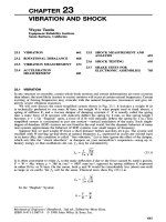
2 VIBRATION MEASUREMENTS
To be able to measure vibration of a machine, some technical equipment is necessary. In
practice, various tools are used, from simple instruments measuring overall vibration to multichannel analyzers equipped with numerous features that facilitate not only the measurement
itself but also the analysis of the measured data.
In this chapter, the typical scheme of vibration analyzer and various types of sensors that
are used for vibration measurements will be introduced. Furthermore, analysis and evaluation
of the vibration measurements will be described.
2.1 Analyzer
Basic scheme of the analyzer used for vibration measurements is in Fig. 2.1. The analogue
signal from the vibration sensor passes through the input amplifier, anti-aliasing filter and
A/D converter, where it is digitized and enters the data buffer. From the buffer it can be
displayed either as a time waveform or can be further processed by the Fourier transform to
obtain frequency spectrum. Individual functional units of the analyzer will be discussed in
detail in the following chapters.
overload
current
source
anti-aliasing
filter
fMAX
vibration
transducer
incoming
signal
(analogue)
buffer
A/D
converter
filter
input
amplifier
sample & hold
circuit
digitized
digitized
window
selection
external
trigger
pulse
circuit
sample
clock
FFT
processor
sample
frequency = 2,56×fMAX
time
display
spectrum
display
Fig. 2.1 - Vibration Analyzer Scheme
2.2 Vibration Transducers
In chapter 1.6 it was stated that any of the three quantities describing the vibratory motion
can be measured. Depending on the measured quantity, sensors are divided into:
-
displacement transducers (proximity probes)
velocity probes (velometers)
accelerometers
23
Usable frequency response and dynamic range differ for various types of sensors. The
dynamic range of a sensor is the range of amplitudes of the measured quantity that can be
measured by the sensor. Choosing the right type of sensor depends both on the application
(for example, whether shaft vibration or vibration of machine case are measured) and on the
frequency range of interest. As shown in Figure 1.13, the non-contact displacement sensors
have the upper frequency limit at approximately 2000 Hz. But already in the range from 1000
to 2000 Hz, measurements performed by non-contact proximity probes are very suspicious
because it is not possible to adequately eliminate the influence of unevenness of the shaft
surface, which is comparable to the measured displacements.
Velocity transducers are limited because of their design to frequencies of approximately
10-1500 Hz. Accelerometers that can measure frequencies lower than 1 Hz to about 30 kHz
have the widest frequency range.
Further on, the individual types of sensors, their typical applications and mode of operation
will be described.
2.2.1
Displacement Transducers
There are several types of sensors to measure displacement, distance or position. The
oldest type is probably a contact mechanical slider; nowadays, the often used type is a noncontact sensor based on eddy currents - proximity probe which operates on the base of change
of Foucault currents - the resistance of the material changes due to the change in distance.
Other types, such as laser, ultrasonic, capacitive or inductive sensors, also exist. Displacement
sensors are quite complex systems; so, they are only used for shaft vibration measurement they measure vibrations of shaft relative to a part of stator, usually relative to the bearing
housing.
The proximity probe based on eddy currents measures the distance between the sensor tip
and a conductive surface. The measuring system comprises the sensor and the proximitor (see
Fig. 2.2). The oscillator in proximitor generates high-frequency alternating current that passes
through a coil embedded in the sensor tip and creates high-frequency electromagnetic field
around the tip of the sensor. Bias voltage used to be -10 Vdc, but may be up to -24 Vdc
(depending on the manufacturer); an alternating component has a frequency of about 1.5 MHz
(depending on the manufacturer). The electromagnetic field in the coil induces eddy
(Foucault) currents in the conductive material. These eddy currents absorb energy from the
system, resulting in the change in impedance of the coil. Instant distance to the target surface
would modulate itself onto this wave and then is demodulated. With respect to the high
frequency of the electromagnetic field, the entire measurement is strongly dependent on the
total resistance (all of ohmic, inductive and capacitive resistance). Cables leading the highfrequency signal are produced in strict tolerances of electrical values and their length cannot
be modified. Any damage to the cable or the shield threatens the quality of measurements.
After affecting the carrier wave and eddy current by the variable distance of the target surface
during the vibration, the signal is led back to the demodulator. Then - now already lowfrequency - the signal is led to the evaluation unit.
24
eddy
currents
shaft of
conductive
material
high-frequency
electromagnetic field
extension
cable and
probe
proximitor
voltage [V]
measured
material
oscillator
detector
voltage
gap between the probe
and measured surface
Fig. 2.2 - Scheme of the Proximity Probe System Based on Eddy Currents
outputs [Vdc]
If the distance between the tip of the sensor and the conductive surface is constant, output
voltage depends on the frequency of the electromagnetic field, the conductivity of the
measured material and its magnetic permeability. It is obvious that sensors of this type are
supplied according to a particular shaft material and may not be used for the shaft made of
different material. In Fig. 2.3 an example of the sensitivity characteristics of the same probe to
different target materials is shown. A common value of sensitivity is 8 mV/µm.
Note:
1 mils = 1/1000 inch = 0,0254 mm
gap from probe tip to the test surface [mils]
Fig. 2.3 - Example of the Probe Sensitivity to Different Materials
It is therefore appropriate to have a sizing agent, which is simple - the micrometer screw
and a bracket for the target material. In addition, it is very important to specify the type of
probe with regard to the target material while purchasing the probe.
25