Microlog GX do 2 kenh bump test
Bạn đang xem bản rút gọn của tài liệu. Xem và tải ngay bản đầy đủ của tài liệu tại đây (451.09 KB, 41 trang )
2 Channel / Balancing / Bump Test /
and Recorder Measurement Overview
2010-04-21 ©SKF Slide 1 [Code]
SKF [Organisation]
Module Objective(s)
To overview “advanced” applications available on the GX
Series Microlog, including:
• Two channel measurements
• Balancing measurements
• Bump Tests
• Recording vibration signals
2010-04-21 ©SKF Slide 2 [Code]
SKF [Organisation]
Two Channel
Measurements
2010-04-21 ©SKF Slide 3 [Code]
SKF [Organisation]
Two Channel Measurement Overview
•
•
•
Two channel
measurements may be
triggered or non triggered
For simultaneous two
channel measurements,
one of the two channel
inputs must be input Y
(CH2)
Not able to view orbit
displays in the Microlog’s
Review mode
2010-04-21 ©SKF Slide 4 [Code]
SKF [Organisation]
Orbit
Time X vs. time Y, unfiltered or orderfiltered (up to 8 orders), plus DC gap
measurement
Dual
Spectrum
Spectra of both input channels
captured and displayed simultaneously
Dual-Time
Time waveforms of both input channels
captured and displayed simultaneously
CrossChannel
Phase
Phase of input X relative to input Y:
Both spectra are stored and phase is
displayed as a table of
magnitude/phase pairs with up to 8
orders
2 Ch. Meas. Accessed from Non ROUTE
Mode
•
Select the Orbit
standard meas.
type, or
•
Set up User
defined two
channel meas.
with X & Y inputs
•
•
•
dual spectrum
dual time
cross channel
phase
2010-04-21 ©SKF Slide 5 [Code]
SKF [Organisation]
Orbit Measurement Overview
•
An “orbit” measures the path of a shaft
centerline motion during rotation
•
Machines such as large centrifugal
compressors, primary and secondary
steam turbines, and large gearboxes
•
Machinery that uses pressure fed
sleeve bearings is normally both critical
to plant operations and very expensive
to repair
•
It is essential that these rotors are
effectively monitored, protected, and
maintained to the highest standard
2010-04-21 ©SKF Slide 6 [Code]
SKF [Organisation]
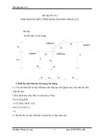
Orbit Measurement Sequence
orbit meas. selection
2010-04-21 ©SKF Slide 7 [Code]
SKF [Organisation]
orbit meas. setup
orbit meas. display
Orbit Measurement Display
shaft speed
•
Results saved as four
individual meas.
•
•
X / Y displacement
at cursor position
Two overall displays
for the DC Gap
measurements, one
for CH1, the next for
CH2
Two graphic displays
for the two dynamic
orbit traces, one for
CH1, the next for
CH2
2010-04-21 ©SKF Slide 8 [Code]
SKF [Organisation]
cursor (dot) at trigger
location (line)
shaft position relative
to rotational center for DC gap
measurements
view dual time
waveforms
2 CH Spectrum / Time Waveform Meas.
•
Spectra / time waveforms of
both input channels captured
and displayed simultaneously
•
Both channel traces are
displayed in a split screen
•
1 – to display only the upper
trace
•
2 – to display only the lower
trace
•
3 – to display both traces
(default)
2010-04-21 ©SKF Slide 9 [Code]
SKF [Organisation]
2 CH Spectrum / TW Meas. Setup
∗ Specify the Configuration menu’s
Single Shot or Continuous
option
•
Specify the Non ROUTE / User /
Display Format option as either
Spectrum or Time
•
Specify the Non ROUTE / User /
Input Channel option as either X
& Y or Z & Y
•
Configure other User setup
screen parameters as needed
2010-04-21 ©SKF Slide 10 [Code]
SKF [Organisation]
2 CH Spectrum / TW Meas. Display
•
Stored as two individual
measurements
•
Spectrum / time
waveform for CH1
•
Spectrum / time
waveform for CH2
2 CH Spectrum Display
2010-04-21 ©SKF Slide 11 [Code]
SKF [Organisation]
2 CH Time Waveform Display
Cross Channel Phase Meas.
•
Relative Phase - phase difference
of input X relative to input Y
•
Both spectra are stored and may
be displayed
•
Phase is displayed as a table of
magnitude/phase pairs with up to
8 orders of running speed
2010-04-21 ©SKF Slide 12 [Code]
SKF [Organisation]
Cross Channel Phase Meas. Setup
•
Specify the Non ROUTE / User /
Display Format option as Phase
•
Specify the Non ROUTE / User /
Input Channel option as either X
& Y or Z & Y
•
Configure other User setup
screen parameters as needed
2010-04-21 ©SKF Slide 13 [Code]
SKF [Organisation]
Specify RPM Options
•
Three options for entering the RPM for
cross channel phase meas.
•
dBase - Take the RPM value from the
GX’s database, if previously assigned
to the POINT
•
Type In - Type in the value using the
numeric keypad, or
•
Spec - Select the 1X RPM frequency
from a spectrum display.
2010-04-21 ©SKF Slide 14 [Code]
SKF [Organisation]
Cross Channel Phase Table
CH 1 and CH2
magnitude
readings for eight
orders
•
T key toggles between
phase table and spectral
displays
•
CH1 spectrum is
displayed first
•
1, 2 and 3 keys
respectively display
CH1, CH2, or dual
traces of CH1 and CH2
2010-04-21 ©SKF Slide 15 [Code]
SKF [Organisation]
shaft speed
cross channel phase
readings for eight
orders
Cross channel
phase reading for
highlighted order
Cross-Channel Phase Meas. Storage
•
Stored as two individual
measurements in the Review
mode, occupying two lines
on the Non-ROUTE Review
screen
•
The first measurement is the
CH1 spectrum, with the
relative phase angle table
•
The second measurement is
the CH2 spectrum, without
the relative phase angle
table
2010-04-21 ©SKF Slide 16 [Code]
SKF [Organisation]
Balancing
Measurements
2010-04-21 ©SKF Slide 17 [Code]
SKF [Organisation]
Disclaimer
•
Real life balancing conditions require
a thorough understanding of
machinery vibration and balancing
techniques. We strongly suggest
you attend the SKF Reliability
Maintenance Institute Machinery
Balancing course to gain balancing
skills necessary for successful
machinery balancing jobs.
•
This course’s Balancing module
simply overviews the Microlog’s
balancing capabilities and introduces
a single-plane balancing procedure to
familiarize you to the machinery
balancing process.
2010-04-21 ©SKF Slide 18 [Code]
SKF [Organisation]
Microlog Balancing Overview
•
Resolves single-plane, two-plane, and static-couple
balances with high precision
•
Interfaces with off-the-shelf laser tachometers,
optical tachometers, or stroboscopes for balancing
phase measurements
•
Balancing requires a shaft 1X signal either to the
external trigger BNC input or to the phase adapter
connector
•
A TTL trigger is not required. The Microlog allows
for an external analog trigger, with an appropriate
trigger threshold
2010-04-21 ©SKF Slide 19 [Code]
SKF [Organisation]
Microlog Balancing Overview
•
Balancing “wizards” provide
clear, comprehensive setup
menus and easy-to-follow
display screens with
graphical data
representations to ensure
easy, accurate balancing
jobs
2010-04-21 ©SKF Slide 20 [Code]
SKF [Organisation]
additiona
l setup
options
stored
balancin
g jobs
Balancing “Run” Overview
•
Stop - Set Up Balancing Equipment and
Measurement Parameters
•
•
•
•
•
•
•
Spin - Perform the Reference Run
Stop - Attach a Trial Weight
Spin - Perform the Trial Run
Stop - Attach the Permanent Correction Weight
Spin - Perform a Correction Weight Run
Stop - If Necessary, Attach a Trim Weight
Spin - Perform a Trim Run
2010-04-21 ©SKF Slide 21 [Code]
SKF [Organisation]
Example Balancing Run Screens
2010-04-21 ©SKF Slide 22 [Code]
SKF [Organisation]
Performing
Bump Tests
2010-04-21 ©SKF Slide 23 [Code]
SKF [Organisation]
Bump Test Overview
•
When impacted, an object's natural or resonant
frequencies are excited. A spectrum taken while the
object is vibrating due to the impact shows spectral
peaks that identify the object's natural frequencies.
•
Vibration forces transmitted by rotating machines
often excite natural resonance in attached structures.
Whenever such structural resonance appears,
vibration responses are amplified and can result in
fatigue failures.
•
Identifying the machine’s resonance frequencies
allows a maintenance engineer the opportunity to
change the resonance frequency so as to reduce or
eliminate damaging vibration.
2010-04-21 ©SKF Slide 24 [Code]
SKF [Organisation]
Bump Test Menu
set up a new
bump test and
begin data
collection
review stored
bump test results
recall previous bump
test meas. setups for
reuse
2010-04-21 ©SKF Slide 25 [Code]
SKF [Organisation]