REBA VI 09 2010
Bạn đang xem bản rút gọn của tài liệu. Xem và tải ngay bản đầy đủ của tài liệu tại đây (623.5 KB, 13 trang )
Rolling Element Bearing Analysis
Rolling-Element Bearing
Analysis
(R.E.B.A.)
Techniques and Practices
Presentation Topics
Considerations in Making the Measurement
Analyzing & Experiences in the Field
Dennis Shreve
Commtest, Inc.
Considerations in Pinpointing Problems
Vibration Institute
Piedmont Chapter – 17 September 2010
1
Copyright 2010 Commtest, Inc.
Follow-up Points and Discussion
2
Getting Down to Basics
Meaningful R.E.B. Analysis
• A bearing carries the load by round elements placed
between two pieces.
• Relative motion of two pieces causes rolling, with very
little resistance or friction.
• Started with logs on the ground with a stone block on top!
((Log
g at back was moved to ffront,, sequentially.)
q
y)
• Rolling elements in a circular bearing are captive and do
not fall out under load.
• R.E.B. offers a good trade-off on cost, size, weight,
carrying capacity, durability, accuracy, low friction, …..
and the list goes on.
• There are lots of product offerings, tools, and
techniques available.
• Sometimes just making the choices can be a bit
intimidating and overwhelming.
• We need to take away some of the “mystery”.
• We need to make the best of the situation.
• We will now examine the history, scientific
terminology, and industry jargon.
3
Copyright 2010 Commtest, Inc.
Copyright 2010 Commtest, Inc.
4
Copyright 2010 Commtest, Inc.
1
Why Do Bearings Fail?
•
•
•
•
•
Take a Proactive Approach
• Choose the correct bearing for the application.
• Employ proper bearing installation techniques.
• Utilize proper skills in assembly, balancing,
alignment etc.
alignment,
etc
• Follow proper lubrication schedule.
• Use care in storage, shipping, and handling.
• Ensure proper operation.
• Train everyone on the value of these good practices.
• Take the time to do the job right!
Poor design.
Misapplication.
P
Poor
iinstallation.
t ll ti
Improper loading.
Poor care and maintenance.
Design Engineering – Application Engineering – Maintenance
5
Copyright 2010 Commtest, Inc.
6
What is L10 Life?
Facts on Bearing Life / Failure
•
•
•
•
•
•
Copyright 2010 Commtest, Inc.
Less than 10% achieve design life.
**
16% fail due to handling and installation.
14% fail due to contamination.
36% fail due to inadequate lubrication.
34% fail due to fatigue issues (excessive loading).
Any extra loading (e.g. misalignment, unbalance, resonance)
reduces life by a cubed function.
• It is the life expectancy for 90% of the population.
• Full load life is estimated at 1,000,000 revolutions.
• Sounds impressive, but at 3600 RPM, this is only 4.6
hours!
• Guidelines….
– Light load is at < 6%.
– Normal load is 6% to 12%.
– Heavy load is at >12%.
¾ L10= (16,667/RPM)* (rated load/actual load)3
• 10% extra loading cuts life by 1/3
• 20% extra loading cuts life by half!
** Source: SKF Bearing Journals.
From a few months to years at continuous 365/24 usage.
7
Copyright 2010 Commtest, Inc.
8
Copyright 2010 Commtest, Inc.
2
What Do We Wish To Accomplish?
The Detection Technologies
• Early detection of even the slightest fault
appearing with the bearing.
• Avoidance of any down time and secondary
damage due to bearing failure
failure.
• Pinpoint the faulty component and possible
cause of the excessive vibration.
• Decide a corrective course of action.
• Follow-up and verify.
• Vibration analysis and acoustic emission.
• Oil and wear particle analysis.
• Infrared thermography.
Each technology has its place and should be used where
appropriate. (Many times, they are complementary.)
Familiar Key Elements: Detection – Analysis – Correction – Verification
9
Copyright 2010 Commtest, Inc.
10
Vibration and the Sources
• We can typically break vibration down to 4
main components:
– Forced vibration due to unbalance, misalignment,
blade and vane p
pass,, ggear mesh,, looseness,,
impacts, resonance, etc.
– Resonance response due to impacts.
– Stress waves or shock pulses.
– Frictional vibration.
11
Copyright 2010 Commtest, Inc.
Copyright 2010 Commtest, Inc.
It’s All About Pattern Recognition
• Vibration measurements provide us with four
basic spectrum (FFT) patterns:
– Harmonics - Almost always caused by the TWF
shape.
– Sidebands - Due to Amplitude or Frequency
Modulation.
– Mounds/Haystacks - Random vibration occurring
in a frequency range.
– Raised Noise Floor - White noise or large random
events.
12
Copyright 2010 Commtest, Inc.
3
What Are We Looking For?
TWF to FFT
• Detection of a even the slightest metal-to-metal
contact from impacting components or inadequate
lubrication in a bearing.
• A slight ringing caused by a bearing fault resonating
a natural frequency in the machinery setup.
• Presence of high-frequency,
high frequency low-energy
low energy vibration
vibration.
– Sometimes noted as raising the “carpet level” in
the noise floor in acceleration readings –
especially at high frequency.
• Capability to detect an incipient failure with senses
that transcend normal human abilities .. sight,
sound, touch, smell, etc.
Complex
to
Simple
“The Signature”
Note: It is not important as to what natural frequency is excited; the measurement just
needs to be repeatable.
13
Copyright 2010 Commtest, Inc.
14
Copyright 2010 Commtest, Inc.
Isn’t It Just Math?
Tell-Tale Signs in Acceleration
Yes. Just know FTFI, BSF, BPFO, and BPFI.
Presence of very small peaks at High Frequency!
15
Copyright 2010 Commtest, Inc.
(assumes a fixed outer race)
16
Copyright 2010 Commtest, Inc.
4
A Look at Geometry …
Fortunately .. It’s All Worked Out
Impacts per
Revolution
Note: BPFI + BPFO = Number of
Elements; typically a 60/40
relationship.
Ball Bearings
Roller Bearings
g
(
(See
data at left.
f 11.349 + 8.651 = 20
rolling elements.)
Also, sometimes estimated as:
BPFI = NB/2 + 1.2
BPFO = NB/2 - 1.2
17
Copyright 2010 Commtest, Inc.
18
Typical Failure Stages?
What Are The Typical Failure Stages?
• STAGE 2:
– More ringing occurring, and presence of
frequencies of 500Hz to 5KHz.
– Fault frequencies show up with modulation
(sidebands).
– Time waveform of acceleration shows impacting
(flat-topped or notched).
– Bearing life down to 5-10%.
• STAGE 1:
– Presence of ultrasonic frequencies (typically well
above 5KHz) that are barely detectable.
– Very low amplitudes appearing in the acceleration
measurement.
– Life remaining at this point is 10-20%.
19
Copyright 2010 Commtest, Inc.
Copyright 2010 Commtest, Inc.
20
Copyright 2010 Commtest, Inc.
5
Typical Failure Stages?
Typical Failure Stages?
• STAGE 3:
– Energy spreads more down the spectrum.
– Defect frequencies begin to be more prominent.
– More harmonics and sidebands show up.
– Wear tend to flatten out peaks and patterns.
– Bearing temperature increase is now apparent.
– It is time to order parts and start an action plan!
– Bearing life is now 5% or less.
21
• STAGE 4:
– 1X energy begins to increase as clearance is quite
noticeable.
ti bl
– Broadband spectral noise is evident by a raised noise
floor.
– Failure is eminent!
– 1% life is remaining at best.
22
Copyright 2010 Commtest, Inc.
What Causes This Vibration Energy?
What Do The Experts Say?
impacts and ringing
present
Copyright 2010 Commtest, Inc.
• Contact between two metal surfaces.
• A shock (or pressure) wave is created.
– Analogy is the wave set up by an earthquake or tsunami.
– A ripple from a pebble tossed in a pond is another example.
• Resulting
R lti signal
i l propagates
t through
th
h the
th metal
t l surfaces
f
when
h
there are no air gaps to filter (good metal-to-metal contact).
Courtesy of Technical Associates of Charlotte ©
23
Copyright 2010 Commtest, Inc.
24
Copyright 2010 Commtest, Inc.
6
How Have Solutions Suppliers
Addressed This Need?
How Can We Detect Early Signs?
• Special instrumentation and detection circuits.
• Special signal processing.
• Detection of small spikes with short duration and ringing
characteristics.
• A small tell-tale
tell tale signal in the presence of lots of noise and
higher amplitudes (a high dynamic range > 95dB).
• Accelerometer with a solid mounting.
• Good measurement practices.
• Special measurement for defect detection, plus normal
readings in 3 axes.
25
Copyright 2010 Commtest, Inc.
• Lots and lots of competitive and complementary
offerings, some dating back to the early 70’s:
–
–
–
–
–
–
–
–
–
26
Spike Energy™ and Spike Energy Spectrum™
ESP™ ( Envelope Signal Processing)
HFD ™ (High Frequency Detection)
SEE ™ ( Spectral Emitted Energy)
PeakVue ™
Shock Pulse ™
Stress Waves
Enveloping (or Demodulation)
Cepstrum
Copyright 2010 Commtest, Inc.
Is There a Common Thread?
The Choices …
• All methods are based on a fundamental concept: There are
repetitive impacts in the machine structure that indicate
bearing faults, gear damage, looseness, cavitations, and similar
faults.
• Machine/bearing resonances (or sensor resonance) are excited by
the impacts – similar to striking a bell.
• Repetitive fault frequencies can be identified with special signal
processing – filtering, peak detection, and frequency analysis.
• Careful measurement and collection methods are essential to
enable this technique.
• Advanced signal processing technology and instrumentation
available today make this a proven analysis tool in routine data
collection programs for Predictive Maintenance (PdM).
27
Copyright 2010 Commtest, Inc.
28
Copyright 2010 Commtest, Inc.
7
What Are the Basic Requirements?
What Do We Need To “See”?
•
•
•
•
• Spikes from impacts.
• Ringing from a natural resonance being excited.
• Demodulation (or other method) to determine and
“see”
see the repeated fault frequency.
frequency
• Frequency Determination on ‘Impact Rate’ to
isolate the fault.
Solid Transducer Mounting.
Mounting Target and Orientation Maintained.
Mounted in Load Zone of Bearing Housing.
Best Possible Mechanical Interface for Transmission of
Energy.
High Frequency Energy Detection Method.
D t ti off Repeated
Detection
R
t d Fault
F lt andd Ringing
Ri i Condition.
C diti
Ability to Strip Out Low Frequencies Associated with Actual
Running Speed.
Ability to Demodulate (Envelope) Signal or Determine the
Peaks of the Repetitive Fault Frequency.
Ability to Detect Repetition Fault Frequency.
Ability to Show Resulting Signature (FFT) and Compare the
Pattern to Published Data.
•
•
•
•
•
•
the impact and ringing
High-pass – Repetitive Peaks in TWF – Low-pass – FFT
29
Copyright 2010 Commtest, Inc.
30
Copyright 2010 Commtest, Inc.
What Does “Demodulation”
Really Mean?
The Measurement Challenge
•
• The mounting method is of key importance.
• We cannot “see” high frequency vibration unless
the mount is a solid mechanical interface.
•
•
•
•
•
•
Better
31
Copyright 2010 Commtest, Inc.
32
It is analogous to stripping out the information from an AM radio
broadcast.
– Spanning the band for the station frequency (540-1600 KHz)
and picking off the broadcasted signal.
First need to incorporate a high-pass or band-pass filtering.
Eliminate any
y high
g amplitude
p
signals
g
associated with 1X and
multiples up to about 10X.
Include only the fault frequencies exciting inherent resonance.
Intensify and draw out repetitive components of the fault.
Convert to frequency for display of the pattern.
Amplitudes will show up as a distinctive “saw-tooth” or “comb”
harmonic pattern of the actual bearing fault.
Copyright 2010 Commtest, Inc.
8
More on Amplitude Modulation
Impact events
generate high-freq
pulses.
• Amplitude Modulation (AM)
– One frequency (carrier) is getting
louder and softer at another
f
frequency
(the
( h modulating
d l i
frequency).
– AM is mono. Mono is ‘one’,
which implies one sideband on
each side of the carrier.
We see...
We don’t see…
((but would like))
X
vibration
vibration
BPFO
BPFO
Carrier
time
time
BPFO
Modulation
frequency
33
Copyright 2010 Commtest, Inc.
34
frequency
Copyright 2010 Commtest, Inc.
The Instrument Signal Processing …
Can The Reading Be Trended?
The raw signal includes low frequency running speed harmonics:
These are removed by band-pass filtering:
• Yes, but consistency of measurement is of
utmost importance.
–
–
–
–
Then envelope detection is applied:
Finally the result is displayed in the frequency domain:
S
Same
hhardware.
d
Same measurement location.
Solid mounting in good mechanical transfer path.
Same conditions.
BPFO
The “comb” or “saw tooth” pattern.
35
Copyright 2010 Commtest, Inc.
36
Copyright 2010 Commtest, Inc.
9
Case History Example
First, Acceleration
•
•
•
•
•
•
•
Automotive paint facility.
250 HP motors running 6-foot bladed exhaust fans.
Motor running at 1792 RPM.
Fan belt driven and running at 820 RPM.
Bearings known.
Excessive vibration reported.
reported
Initial measurements made of vibration with acceleration,
velocity, and demodulation.
• Source of problem is identified, corrective action is
recommended.
• Bearing SKF 22218CCK changed out at next production
break.
• Let’s take a look at initial results first, then Before/After
comparisons.
37
Copyright 2010 Commtest, Inc.
classical lifting of noise floor at high frequencies
38
Next, Velocity
Copyright 2010 Commtest, Inc.
Now, Demodulation
dominant BPFI fault frequency
High running speed components
39
Copyright 2010 Commtest, Inc.
40
Copyright 2010 Commtest, Inc.
10
After the Fact, but not obvious
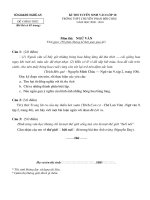
Velocity – Before and After
Power (in/s 0-pk)
FAN02 - Pulley End - Horizontal - Vel Freq 96000 CPM
0.46
0
O/All 0.187 in/s 0-pk
0.35
0.3
in/s 0-pk
0.25
Note the significant reduction in amplitude.
0.2
0.15
0.1
0.05
0
0
10,000
20,000
30,000
40,000
50,000
60,000
70,000
80,000
90,000
CPM
41
1/13/2006 1:29:38 PM
O/All 0.187 in/s 0-pk
820 RPM
12/28/2005 4:03:26 PM
O/All 0.343 in/s 0-pk
820 RPM
42
Copyright 2010 Commtest, Inc.
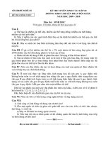
Acceleration – Before and After
Copyright 2010 Commtest, Inc.
Demodulation – Before & After
22218CCK BPFI
FAN02 - Pulley End - Horizontal - Demod (1000-2500Hz) 30000 CPM
O/All 0.179 g 0-pk
0.04
0.16
0.035
0.14
Note the reduction of the high-frequency energy.
4.722 orders
0.003 g
O/All 0.149 g rms
22218CCK BPFI
0.025
g rms
0.1
g 0-pk
3871.875 CPM
0 03
0.03
0.12
0.08
0.02
0.06
0.015
0.04
0.01
0.02
0.005
0
Note that the distinctive peaks are gone!
0
0
20,000
40,000
60,000
80,000
100,000
0
120,000
2,000
4,000
6,000
CPM
43
Cursor A:
22218CCK BPFI
0.18
FAN02
Pulley End
Horizontal
Acc Time 400 ms
1/13/2006 1:56:07 PM
O/All 0.179 g 0-pk
1785 RPM
FAN02
Pulley End
Horizontal
Acc Time 400 ms
11/10/2005 12:55:02 AM
O/All 0.365 g 0-pk
817.5 RPM
Copyright 2010 Commtest, Inc.
1/13/2006 1:34:06 PM
12/29/2005 12:46:44 AM
44
8,000
10,000 12,000 14,000 16,000 18,000 20,000 22,000 24,000 26,000 28,000 30,000
CPM
O/All 0.052 g rms
O/All 0.149 g rms
820 RPM
820 RPM
Copyright 2010 Commtest, Inc.
11
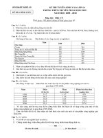
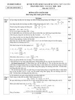
Another Recent Finding
First, The High Frequency Data
High Freq Spectrum
5/8/2009 1:21:42 PM
• Low speed machine turning at 394 RPM.
• Bearing known as FAG 23906B.
• Fault frequencies known:
Resonance, with sidebanding
0.001
5KHz and above resonances with sidebands
BPFI is 18.889
18 889
BPFO is 16.111
BSF is 6.2
FTFI is 0.46
0.0008
g 0-pk
0.0006
0.0004
• Low vibration amplitudes, but somewhat noisy.
• High frequency acceleration data was taken along
with routine measurements, no demod.
0.0002
0
200,000
800,000
1,400,000
1,600,000
1,800,000
2,000,000
2,200,000
2,400,0
EP252 JN1162 - Bracket at Quill bearing - Axial - Acc Spec/Wfm 48000 CPM "Accel 'g' pk LOW"
5/8/2009 1:21:16 PM
Cursor A:
-0.001 g
-0.001 g
0g
15844.093 CPM
40.213 orders
0g
O/All 0.001 g 0-pk
0.0012
EP252 JN1162 - Bracket at Quill bearing - Axial - Acc Spec/Wfm 480000 CPM "Acc pk 'g' HIGH"
5/8/2009 1:21:35 PM
O/All 0.001 g 0-pk
O/All 0.003 g 0-pk
0.001
BPFI Fault Frequency is evident
23960B BPFI (+/- 1X) +2.02%
23960B BPFI (+/- 1X) +2.02%
0.0002
23960B BPFI (+/- 1X) +2.02%
0.0004
0.0002
23960B BPFI (+/- 1X) +2.02%
g 0-pk
0.0004
Impacts separated by BPFI
23960B BPFI (+/- 1X) +2.02%
-0.001
0.0006
23960B BPFI (+/- 1X) +2.02%
g 0-pk
g
0.0006
23960B BPFI (+/- 1X) +2.02%
0 0008
0.0008
0
23960B BPFI (+/- 1X) +2.0
02%
0.001
0.0008
23960B BPFI (+/- 1X) +2.02%
0.001
1,200,000
CPM
23960B BPFI (+/- 1X) +2.02%
0.057 secs
0.065 secs
0.008 secs
7227.271 CPM
1,000,000
Finally, the FFT with Overlays
EP252 JN1162 - Bracket at Quill bearing - Axial - Acc Spec/Wfm 48000 CPM "Accel 'g' pk LOW"
5/8/2009 1:21:16 PM
0.372 Revs
0.426 Revs
0.055 Revs
18.343 orders
600,000
Copyright 2010 Commtest, Inc.
Next, the Time Waveform
Cursor A:
Cursor B:
Diff:
Diff:
400,000
46
Copyright 2010 Commtest, Inc.
23960B BPFI (+/- 1X) +2.02
2%
45
23960B BPFI (+/- 1X) +2.02%
–
–
–
–
O/All 0.004 g 0-pk
0.0012
Repetitive spiking at BPFI
-0.002
0
0
0
0.2
0.4
0.6
0.8
1
1.2
1.4
1.6
1.8
2
O/All 0.001 g 0-pk
394 RPM
10,000
15,000
20,000
<add note>
Copyright 2010 Commtest, Inc.
0
20,000
25,000
CPM
30,000
35,000
40,000
45,000
-0.0002
Revs
5/8/2009 1:21:16 PM
47
5,000
40,000
60,000
80,000
100,000
120,000
140,000
CPM
48
Copyright 2010 Commtest, Inc.
12
Summary Remarks
Pre-requisites and Procedure
•
•
•
•
Bearing part number(s) must be known.
Fault frequencies must be known and preloaded.
Running speed must be accurately recorded.
Bearing faults excite natural resonances in the machine
components or transducer.
• The fault frequency is recurring.
• A technique is available to detect the repetition rate in
time.
• The fault frequency (if present) can be shown in an FFT
display with bearing data overlays.
49
Copyright 2010 Commtest, Inc.
• Machinery vibration measurements in time waveform and
spectrum can provide early (tell-tale) signs of rolling element
bearing defects.
• Special signal processing techniques (now available in most
portable data collectors) can detect impacting spikes and
pinpoint a specific fault frequency.
• Comparing the resulting signature (pattern) to published fault
frequencies can pinpoint the root cause of the problem.
• Field experiences in PdM over 30 years have proven the
concepts to be very accurate and reliable.
• Considerable cost savings (in maintenance and production) are
afforded by use of this technology.
50
Copyright 2010 Commtest, Inc.
Questions / Discussion
on
Rolling Element Analysis?
Email:
51
Copyright 2010 Commtest, Inc.
13