Static and dynamic presentation 05 2009
Bạn đang xem bản rút gọn của tài liệu. Xem và tải ngay bản đầy đủ của tài liệu tại đây (4.77 MB, 140 trang )
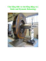
S tatic & Dynamic
Mo to r Te s ting
Dre w No rman
Ap p lic atio ns Eng ine e r
VIBRATION INS TITUTE
Pie d m o nt Chap te r #14
2009 Annual S e m inar
Mo to r Failure Are as
IEEE Study (Early 1990’s)
EPRI Study (Mid 1990’s)
S tatic Mo to r
Te s ting
Intro to S tatic Mo to r Mo nito ring
De fining S tatic (Off-Line ) Ele c tric Mo to r
Te s ting
WHAT IS IT: Me a s uring a nd tra cking e le ctrica l prope rtie s of the
winding circuit in a n e ffort to de te rmine its he a lth a nd re lia bility while
the motor is de e ne rgize d.
HOW:
Low Volta ge Te s ting
Me a s uring s pe cific e le ctrica l pa ra me te rs a t or be low na me pla te
volta ge s to de te rmine a cha nge in the e le ctrica l circuit prope rtie s .
High Volta ge Te s ting
Te s ting motor ins ula tion a t volta ge le ve ls s imila r to thos e the motor
e ncounte rs in it’s norma l e nvironme nt.
Winding De s ig n
Ra ndom Winding
(Mus h Winding)
Form Coil
Te s ting Ins ulatio n S ys te ms
• Multime te rs
• Me g-Ohm-Me te r
• Re s is ta nce Me te rs (DLRO, Bridge s )
• Low volta ge circuit e va lua tion (i.e . Ca pa cita nce ,
Inducta nce )
• High P ote ntia l Te s t – AC-DC
• S urge Te s ting
• Corona Te s ting
• P a rtia l Dis cha rge De te ction
• Infra re d, Ultra s onic, Vibra tion
To pic s o f Dis c us s io n
Ins ula tion S tre ngth
Fa ilure Me cha nis ms
Te s ting The ory
• Te s t P a ra me te rs
• P a ss / Fa il Crite ria
Me thods of Te s ting
P re dictive Indica tors in Ele ctrica l Motor Te s ting
Die le c tric S tre ng th o f Go o d Ins ulatio n
Pro pe rtie s o f the Die le c tric s
Dielectric Strength
Puncture/Breakdown
Wire fo r a 460V AC mo to r has
6000VAC ins ulatio n c apability (NEMA MG-1)
8400 Volts Peak 6000V RMS
Or:
6000 AC 2 = 8400VDC
De mo ns trate the Die le c tric S tre ng th o f the
Mag ne t Wire
One S lot of a 460 volt Motor
Pro pe rtie s o f the Die le c tric s
We dg e
S lo t Ce ll Line r
Phas e Ins ulatio n
Slot liner is 20,000 VDC
Nomex-Mylar-Nomex
Single slot in a
random wound
3 Φ Motor
•Co mbine d Ins ulatio n to Gro und is
8400 VDC + 20,000 VDC = 28,400 VDC
Ins ulatio n Life Curve
N WODKAE RB
E GATL OV
Cu-Ground
28,400VDC
Cu-Cu
16,800VDC
TIME (Years)
Impo rtant Po int
The Die le ctric S tre ngth of Good Ins ula tion is Ve ry High!
MUCH HIGHER THAN THE NAMEP LATE RATING!
Ins ulatio n Life Curve
Cu-Ground
28,400VDC
Cu-Cu
16,800VDC
What is causing it to
degrade over time?
Why is the curve shaped this way?
N WODKAE RB
E GATL OV
Insulation
Failure
Bus Voltage
TIME (Years)
Caus e s o f Ins ulatio n Failure
The rma l Aging (IEEE 101)
• For e ve ry 10C incre a s e in te mpe ra ture of the ins ula tion, the ra te of ins ula tion
de gra da tion is double d.
Ins ulatio n S ys te ms
The rmal Co ntributo rs
• Loa d (Incre a s e d curre nt cre a te s he a t by I2R)
• Ambie nt Conditions
– Te mpe ra ture
– Altitude
• S ta rting Curre nt & Initia l Te mpe ra ture Ris e (Re s ta rts )
• The rma l Ins ula tion from Conta mina tion
• P owe r Qua lity
– Ha rmonic Volta ge Fa ctor
– Unde r a nd Ove r Volta ge
– Volta ge Imba la nce
The rmal Capac ity/ Altitude
Caus e s o f Ins ulatio n Failure
The rma l Aging (IEEE 101)
• For e ve ry 10C incre a s e in te mpe ra ture of the ins ula tion, the ra te of ins ula tion
de gra da tion is double d.
Conta mina tion
• Che mica l, de pos it on the winding a ctive ly a tta ck the ins ula tion
–
(i.e . Acids , Ca us tics , EP -2 Gre a s e )
• S ome conta mina tion ca n a ls o le a d to the rma l ins ula tion
• Abra s ive we a r of ins ula tion due to impa ct from a ir flow
Me cha nica l
• Move me nt within the winding a t s ta rt up
• The rma l growth of ma te ria ls
Ove r Volta ge S pike s
• High Volta ge s urge s ca us e d by Switching, Lightning, VFD’s
Ho w Lo ng S ho uld a Mo to r’s
Ins ulatio n Las t?
100,000 hours
11.4 ye a rs – All Da y, Eve ry Da y, Eve ry Ye a r
100,000 hours
= 4166 days = 11.4 years
24 hours
33 ye a rs – 8 hours a Da y, Eve ry Da y
1
Failure Mechanisms
Turn to Turn Failure
80% of e le ctrica l s ta tor fa ilure s s ta rt a s turn-to-turn fa ult
Mos t will fa il to ground in the s lot a nd s ome pha s e to
pha s e , but the root ca us e will be turn to turn fa ilure
Ge ne ral Ele c tric Pape r
Re as o ns why mo s t failure s be g in as
“turn to turn” failure s
• Turn ins ula tion is the we a ke s t ins ula tion in the motor.
Both Me cha nica lly a nd Die le ctrica lly
• All Contributors to Ins ula tion De gra da tion a re a cting e ve nly on the
winding, howe ve r this winding is more e xpos e d to outs ide influe nce .
(i.e . Conta mina tion, Move me nt, Abra s ion, The rma l Ins ula tion)
• Move me nt from s ta rt up rubs the turns toge the r ca us ing we a r.
(D.E. Cra wford\Ge ne ra l Ele ctric)
• Da ma ge ca us e d by winding a nd ha ndling proce s s .
• S ta rting, S topping, Lighting, a nd VFD’s ca us e volta ge s pike s which in
turn produce high turn to turn volta ge s .
D.E. Crawfo rd, “A Me c hanis m o f Mo to r Failure s .” Ge ne ral Ele c tric
Co mpany, 75CH1014-0-EI-19.
“…Looseness, motion and wear develop as the result of certain stresses
applied to the motor windings by the service it sees. Careful analysis
revealed the following conditions:
Diffe re ntial the rmal s tre s s e s
Varnis h we ake ning at hig he r te mpe rature s
Diffe re nt c o e ffic ie nts o f e xpans io n
Mag ne tic fo rc e due to winding c urre nts ”
“…Wear between the moving components is a natural consequence of
motion and it was found when the likely points were located…”