B31.1 2016 Power Piping
Bạn đang xem bản rút gọn của tài liệu. Xem và tải ngay bản đầy đủ của tài liệu tại đây (3.34 MB, 366 trang )
ASME B31.1-2016
(Revision of ASME B31.1-2014)
Power Piping
ASME Code for Pressure Piping, B31
A N I N T E R N AT I O N A L P I P I N G CO D E ®
ASME B31.1-2016
(Revision of ASME B31.1-2014)
Power Piping
ASME Code for Pressure Piping, B31
A N I N T E R N AT I O N A L P I P I N G CO D E ®
Two Park Avenue • New York, NY • 10016 USA
Date of Issuance: June 30, 2016
The next edition of this Code is scheduled for publication in 2018. This Code will become effective
6 months after the Date of Issuance.
ASME issues written replies to inquiries concerning interpretations of technical aspects of this Code.
Interpretations are published under Periodically certain actions
of the ASME B31 Committees may be published as Cases. Cases are published on the ASME Web
site under the Committee Pages at as they are issued.
Errata to codes and standards may be posted on the ASME Web site under the Committee Pages to
provide corrections to incorrectly published items, or to correct typographical or grammatical errors
in codes and standards. Such errata shall be used on the date posted.
The B31 Committee Pages can be found at The associated B31
Committee Pages for each code and standard can be accessed from this main page. There is an
option available to automatically receive an e-mail notification when errata are posted to a particular
code or standard. This option can be found on the appropriate Committee Page after selecting “Errata”
in the “Publication Information” section.
ASME is the registered trademark of The American Society of Mechanical Engineers.
This international code or standard was developed under procedures accredited as meeting the criteria for American
National Standards and it is an American National Standard. The Standards Committee that approved the code or
standard was balanced to assure that individuals from competent and concerned interests have had an opportunity to
participate. The proposed code or standard was made available for public review and comment that provides an
opportunity for additional public input from industry, academia, regulatory agencies, and the public-at-large.
ASME does not “approve,” “rate,” or “endorse” any item, construction, proprietary device, or activity.
ASME does not take any position with respect to the validity of any patent rights asserted in connection with any
items mentioned in this document, and does not undertake to insure anyone utilizing a standard against liability for
infringement of any applicable letters patent, nor assume any such liability. Users of a code or standard are expressly
advised that determination of the validity of any such patent rights, and the risk of infringement of such rights, is
entirely their own responsibility.
Participation by federal agency representative(s) or person(s) affiliated with industry is not to be interpreted as
government or industry endorsement of this code or standard.
ASME accepts responsibility for only those interpretations of this document issued in accordance with the established
ASME procedures and policies, which precludes the issuance of interpretations by individuals.
No part of this document may be reproduced in any form,
in an electronic retrieval system or otherwise,
without the prior written permission of the publisher.
The American Society of Mechanical Engineers
Two Park Avenue, New York, NY 10016-5990
Copyright © 2016 by
THE AMERICAN SOCIETY OF MECHANICAL ENGINEERS
All rights reserved
Printed in U.S.A.
CONTENTS
Foreword . . . . . . . . . . . . . . . . . . . . . . . . . . . . . . . . . . . . . . . . . . . . . . . . . . . . . . . . . . . . . . . . . . . . . . . . . . . . . .
Committee Roster . . . . . . . . . . . . . . . . . . . . . . . . . . . . . . . . . . . . . . . . . . . . . . . . . . . . . . . . . . . . . . . . . . . . .
Introduction . . . . . . . . . . . . . . . . . . . . . . . . . . . . . . . . . . . . . . . . . . . . . . . . . . . . . . . . . . . . . . . . . . . . . . . . . . .
Summary of Changes . . . . . . . . . . . . . . . . . . . . . . . . . . . . . . . . . . . . . . . . . . . . . . . . . . . . . . . . . . . . . . . . . .
vii
viii
xii
xiv
Chapter I
100
Scope and Definitions. . . . . . . . . . . . . . . . . . . . . . . . . . . . . . . . . . . . . . . . . . . . . . . . . . .
General . . . . . . . . . . . . . . . . . . . . . . . . . . . . . . . . . . . . . . . . . . . . . . . . . . . . . . . . . . . . . . .
1
1
Chapter II
Part 1
101
102
Part 2
103
104
Part 3
105
106
107
108
Part 4
110
111
112
113
114
115
116
117
118
Part 5
119
120
121
Part 6
122
Design . . . . . . . . . . . . . . . . . . . . . . . . . . . . . . . . . . . . . . . . . . . . . . . . . . . . . . . . . . . . . . . . .
Conditions and Criteria . . . . . . . . . . . . . . . . . . . . . . . . . . . . . . . . . . . . . . . . . . . . . . .
Design Conditions . . . . . . . . . . . . . . . . . . . . . . . . . . . . . . . . . . . . . . . . . . . . . . . . . . . . .
Design Criteria . . . . . . . . . . . . . . . . . . . . . . . . . . . . . . . . . . . . . . . . . . . . . . . . . . . . . . . .
Pressure Design of Piping Components . . . . . . . . . . . . . . . . . . . . . . . . . . . . . . .
Criteria for Pressure Design of Piping Components . . . . . . . . . . . . . . . . . . . . .
Pressure Design of Components . . . . . . . . . . . . . . . . . . . . . . . . . . . . . . . . . . . . . . .
Selection and Limitations of Piping Components . . . . . . . . . . . . . . . . . . . . .
Pipe . . . . . . . . . . . . . . . . . . . . . . . . . . . . . . . . . . . . . . . . . . . . . . . . . . . . . . . . . . . . . . . . . .
Fittings, Bends, and Intersections . . . . . . . . . . . . . . . . . . . . . . . . . . . . . . . . . . . . . .
Valves . . . . . . . . . . . . . . . . . . . . . . . . . . . . . . . . . . . . . . . . . . . . . . . . . . . . . . . . . . . . . . . .
Pipe Flanges, Blanks, Flange Facings, Gaskets, and Bolting . . . . . . . . . . . . .
Selection and Limitations of Piping Joints . . . . . . . . . . . . . . . . . . . . . . . . . . . .
Piping Joints . . . . . . . . . . . . . . . . . . . . . . . . . . . . . . . . . . . . . . . . . . . . . . . . . . . . . . . . . .
Welded Joints . . . . . . . . . . . . . . . . . . . . . . . . . . . . . . . . . . . . . . . . . . . . . . . . . . . . . . . . .
Flanged Joints . . . . . . . . . . . . . . . . . . . . . . . . . . . . . . . . . . . . . . . . . . . . . . . . . . . . . . . . .
Expanded or Rolled Joints . . . . . . . . . . . . . . . . . . . . . . . . . . . . . . . . . . . . . . . . . . . . .
Threaded Joints . . . . . . . . . . . . . . . . . . . . . . . . . . . . . . . . . . . . . . . . . . . . . . . . . . . . . . .
Flared, Flareless, and Compression Joints, and Unions . . . . . . . . . . . . . . . . . .
Bell End Joints . . . . . . . . . . . . . . . . . . . . . . . . . . . . . . . . . . . . . . . . . . . . . . . . . . . . . . . .
Brazed and Soldered Joints . . . . . . . . . . . . . . . . . . . . . . . . . . . . . . . . . . . . . . . . . . . .
Sleeve Coupled and Other Proprietary Joints . . . . . . . . . . . . . . . . . . . . . . . . . . .
Expansion, Flexibility, and Pipe-Supporting Element . . . . . . . . . . . . . . . . . .
Expansion and Flexibility . . . . . . . . . . . . . . . . . . . . . . . . . . . . . . . . . . . . . . . . . . . . . .
Loads on Pipe-Supporting Elements . . . . . . . . . . . . . . . . . . . . . . . . . . . . . . . . . . .
Design of Pipe-Supporting Elements . . . . . . . . . . . . . . . . . . . . . . . . . . . . . . . . . . .
Systems . . . . . . . . . . . . . . . . . . . . . . . . . . . . . . . . . . . . . . . . . . . . . . . . . . . . . . . . . . . . . . .
Design Requirements Pertaining to Specific Piping Systems . . . . . . . . . . . . .
14
14
14
15
21
21
21
36
36
36
37
38
39
39
39
40
40
40
45
45
45
46
46
46
49
49
53
53
Chapter III
123
124
125
Materials. . . . . . . . . . . . . . . . . . . . . . . . . . . . . . . . . . . . . . . . . . . . . . . . . . . . . . . . . . . . . . .
General Requirements . . . . . . . . . . . . . . . . . . . . . . . . . . . . . . . . . . . . . . . . . . . . . . . . .
Limitations on Materials . . . . . . . . . . . . . . . . . . . . . . . . . . . . . . . . . . . . . . . . . . . . . . .
Creep Strength Enhanced Ferritic Materials . . . . . . . . . . . . . . . . . . . . . . . . . . . .
68
68
69
71
Chapter IV
126
Dimensional Requirements . . . . . . . . . . . . . . . . . . . . . . . . . . . . . . . . . . . . . . . . . . . . . .
Material Specifications and Standards for Standard and Nonstandard
Piping Components . . . . . . . . . . . . . . . . . . . . . . . . . . . . . . . . . . . . . . . . . . . . . . . . .
73
Fabrication, Assembly, and Erection. . . . . . . . . . . . . . . . . . . . . . . . . . . . . . . . . . . . . .
Welding . . . . . . . . . . . . . . . . . . . . . . . . . . . . . . . . . . . . . . . . . . . . . . . . . . . . . . . . . . . . . . .
Brazing and Soldering . . . . . . . . . . . . . . . . . . . . . . . . . . . . . . . . . . . . . . . . . . . . . . . . .
Bending and Forming . . . . . . . . . . . . . . . . . . . . . . . . . . . . . . . . . . . . . . . . . . . . . . . . .
Requirements for Fabricating and Attaching Pipe Supports . . . . . . . . . . . . .
Welding Preheat . . . . . . . . . . . . . . . . . . . . . . . . . . . . . . . . . . . . . . . . . . . . . . . . . . . . . . .
81
81
92
94
97
97
Chapter V
127
128
129
130
131
iii
73
132
133
135
Postweld Heat Treatment . . . . . . . . . . . . . . . . . . . . . . . . . . . . . . . . . . . . . . . . . . . . . .
Stamping . . . . . . . . . . . . . . . . . . . . . . . . . . . . . . . . . . . . . . . . . . . . . . . . . . . . . . . . . . . . .
Assembly . . . . . . . . . . . . . . . . . . . . . . . . . . . . . . . . . . . . . . . . . . . . . . . . . . . . . . . . . . . . .
97
104
104
Chapter VI
136
137
Inspection, Examination, and Testing . . . . . . . . . . . . . . . . . . . . . . . . . . . . . . . . . . . .
Inspection and Examination . . . . . . . . . . . . . . . . . . . . . . . . . . . . . . . . . . . . . . . . . . .
Pressure Tests . . . . . . . . . . . . . . . . . . . . . . . . . . . . . . . . . . . . . . . . . . . . . . . . . . . . . . . . .
106
106
110
Chapter VII
138
139
140
141
142
Operation and Maintenance . . . . . . . . . . . . . . . . . . . . . . . . . . . . . . . . . . . . . . . . . . . . .
General . . . . . . . . . . . . . . . . . . . . . . . . . . . . . . . . . . . . . . . . . . . . . . . . . . . . . . . . . . . . . . .
Operation and Maintenance Procedures . . . . . . . . . . . . . . . . . . . . . . . . . . . . . . . .
Condition Assessment of CPS . . . . . . . . . . . . . . . . . . . . . . . . . . . . . . . . . . . . . . . . . .
CPS Records . . . . . . . . . . . . . . . . . . . . . . . . . . . . . . . . . . . . . . . . . . . . . . . . . . . . . . . . . .
Piping and Pipe-Support Maintenance Program and Personnel
Requirements . . . . . . . . . . . . . . . . . . . . . . . . . . . . . . . . . . . . . . . . . . . . . . . . . . . . . . .
CPS Walkdowns . . . . . . . . . . . . . . . . . . . . . . . . . . . . . . . . . . . . . . . . . . . . . . . . . . . . . . .
Material Degradation Mechanisms . . . . . . . . . . . . . . . . . . . . . . . . . . . . . . . . . . . . .
Dynamic Loading . . . . . . . . . . . . . . . . . . . . . . . . . . . . . . . . . . . . . . . . . . . . . . . . . . . . .
114
114
114
114
115
144
145
146
Figures
100.1.2(A.1)
100.1.2(A.2)
100.1.2(B.1)
100.1.2(B.2)
100.1.2(B.3)
100.1.2(C)
102.4.5
104.3.1(D)
104.3.1(G)
104.5.3
104.8.4
122.1.7(C)
122.4
127.3
127.4.2
127.4.4(A)
127.4.4(B)
127.4.4(C)
127.4.8(A)
127.4.8(B)
127.4.8(C)
127.4.8(D)
127.4.8(E)
127.4.8(F)
Code Jurisdictional Limits for Piping — An Example of Forced Flow
Steam Generators With No Fixed Steam and Water Line . . . . . . . . . . . . .
Code Jurisdictional Limits for Piping — An Example of Steam Separator
Type Forced Flow Steam Generators With No Fixed Steam and Water
Line . . . . . . . . . . . . . . . . . . . . . . . . . . . . . . . . . . . . . . . . . . . . . . . . . . . . . . . . . . . . . . . .
Code Jurisdictional Limits for Piping — Drum-Type Boilers . . . . . . . . . . . .
Code Jurisdictional Limits for Piping — Isolable Economizers Located in
Feedwater Piping and Isolable Superheaters in Main Steam Piping
(Boiler Pressure Relief Valves, Blowoff, and Miscellaneous Piping
for Boiler Proper Not Shown for Clarity) . . . . . . . . . . . . . . . . . . . . . . . . . . . . .
Code Jurisdictional Limits for Piping — Nonintegral Separately Fired
Superheaters . . . . . . . . . . . . . . . . . . . . . . . . . . . . . . . . . . . . . . . . . . . . . . . . . . . . . . . .
Code Jurisdictional Limits for Piping — Spray-Type Desuperheater . . . . .
Nomenclature for Pipe Bends . . . . . . . . . . . . . . . . . . . . . . . . . . . . . . . . . . . . . . . . . .
Reinforcement of Branch Connections . . . . . . . . . . . . . . . . . . . . . . . . . . . . . . . . . .
Reinforced Extruded Outlets . . . . . . . . . . . . . . . . . . . . . . . . . . . . . . . . . . . . . . . . . . .
Types of Permanent Blanks . . . . . . . . . . . . . . . . . . . . . . . . . . . . . . . . . . . . . . . . . . . .
Cross Section Resultant Moment Loading . . . . . . . . . . . . . . . . . . . . . . . . . . . . . .
Typical Globe Valves . . . . . . . . . . . . . . . . . . . . . . . . . . . . . . . . . . . . . . . . . . . . . . . . . .
Desuperheater Schematic Arrangement . . . . . . . . . . . . . . . . . . . . . . . . . . . . . . . .
Butt Welding of Piping Components With Internal Misalignment . . . . . . .
Welding End Transition — Maximum Envelope . . . . . . . . . . . . . . . . . . . . . . . .
Fillet Weld Size . . . . . . . . . . . . . . . . . . . . . . . . . . . . . . . . . . . . . . . . . . . . . . . . . . . . . . . .
Welding Details for Slip-On and Socket-Welding Flanges; Some
Acceptable Types of Flange Attachment Welds . . . . . . . . . . . . . . . . . . . . . . .
Minimum Welding Dimensions Required for Socket Welding
Components Other Than Flanges . . . . . . . . . . . . . . . . . . . . . . . . . . . . . . . . . . . .
Typical Welded Branch Connection Without Additional
Reinforcement . . . . . . . . . . . . . . . . . . . . . . . . . . . . . . . . . . . . . . . . . . . . . . . . . . . . . . .
Typical Welded Branch Connection With Additional Reinforcement . . . . .
Typical Welded Angular Branch Connection Without Additional
Reinforcement . . . . . . . . . . . . . . . . . . . . . . . . . . . . . . . . . . . . . . . . . . . . . . . . . . . . . .
Some Acceptable Types of Welded Branch Attachment Details
Showing Minimum Acceptable Welds . . . . . . . . . . . . . . . . . . . . . . . . . . . . . . .
Some Acceptable Details for Integrally Reinforced Outlet Fittings . . . . . . .
Typical Full Penetration Weld Branch Connections for NPS 3
(DN 80) and Smaller Half Couplings or Adapters . . . . . . . . . . . . . . . . . . . .
iv
116
116
116
116
2
3
4
5
6
7
19
27
30
34
35
57
62
82
83
86
87
87
87
87
87
88
89
90
127.4.8(G)
135.5.3
Tables
102.4.3
102.4.5
102.4.6(B.1.1)
102.4.6(B.2.2)
102.4.7
104.1.2(A)
112
114.2.1
121.5
121.7.2(A)
122.2
122.8.2(B)
126.1
127.4.2
129.3.1
129.3.3.1
129.3.4.1
131.4.1
132
132.1
132.1.3
132.2
136.4
136.4.1
Typical Partial Penetration Weld Branch Connection for NPS 2
(DN 50) and Smaller Fittings . . . . . . . . . . . . . . . . . . . . . . . . . . . . . . . . . . . . . . . .
Typical Threaded Joints Using Straight Threads . . . . . . . . . . . . . . . . . . . . . . . .
Longitudinal Weld Joint Efficiency Factors . . . . . . . . . . . . . . . . . . . . . . . . . . . . .
Bend Thinning Allowance . . . . . . . . . . . . . . . . . . . . . . . . . . . . . . . . . . . . . . . . . . . . .
Maximum Severity Level for Casting Thickness 41⁄2 in. (114 mm) or
Less . . . . . . . . . . . . . . . . . . . . . . . . . . . . . . . . . . . . . . . . . . . . . . . . . . . . . . . . . . . . . . . .
Maximum Severity Level for Casting Thickness Greater Than 41⁄2 in.
(114 mm) . . . . . . . . . . . . . . . . . . . . . . . . . . . . . . . . . . . . . . . . . . . . . . . . . . . . . . . . . . .
Weld Strength Reduction Factors to Be Applied When Calculating the
Minimum Wall Thickness or Allowable Design Pressure of
Components Fabricated With a Longitudinal Seam Fusion Weld . . . . . .
Values of y . . . . . . . . . . . . . . . . . . . . . . . . . . . . . . . . . . . . . . . . . . . . . . . . . . . . . . . . . . . .
Piping Flange Bolting, Facing, and Gasket Requirements . . . . . . . . . . . . . . .
Threaded Joints Limitations . . . . . . . . . . . . . . . . . . . . . . . . . . . . . . . . . . . . . . . . . . . .
Suggested Steel Pipe Support Spacing . . . . . . . . . . . . . . . . . . . . . . . . . . . . . . . . . .
Carrying Capacity of Threaded ASTM A36, A575, and A576
Hot-Rolled Carbon Steel . . . . . . . . . . . . . . . . . . . . . . . . . . . . . . . . . . . . . . . . . . . . .
Design Pressure for Blowoff/Blowdown Piping Downstream of BEP
Valves . . . . . . . . . . . . . . . . . . . . . . . . . . . . . . . . . . . . . . . . . . . . . . . . . . . . . . . . . . . . . .
Minimum Wall Thickness Requirements for Toxic Fluid Piping . . . . . . . . .
Specifications and Standards . . . . . . . . . . . . . . . . . . . . . . . . . . . . . . . . . . . . . . . . . . .
Reinforcement of Girth and Longitudinal Butt Welds . . . . . . . . . . . . . . . . . . .
Approximate Lower Critical Temperatures . . . . . . . . . . . . . . . . . . . . . . . . . . . . .
Post Cold-Forming Strain Limits and Heat-Treatment Requirements . . . . .
Post Cold-Forming Strain Limits and Heat-Treatment Requirements . . . . .
Preheat Temperatures . . . . . . . . . . . . . . . . . . . . . . . . . . . . . . . . . . . . . . . . . . . . . . . . . .
Postweld Heat Treatment . . . . . . . . . . . . . . . . . . . . . . . . . . . . . . . . . . . . . . . . . . . . . .
Alternate Postweld Heat Treatment Requirements for Carbon and
Low Alloy Steels, P-Nos. 1 and 3 . . . . . . . . . . . . . . . . . . . . . . . . . . . . . . . . . . . .
Postweld Heat Treatment of P36/F36 . . . . . . . . . . . . . . . . . . . . . . . . . . . . . . . . . . .
Exemptions to Mandatory Postweld Heat Treatment . . . . . . . . . . . . . . . . . . . .
Mandatory Minimum Nondestructive Examinations for Pressure
Welds or Welds to Pressure-Retaining Components . . . . . . . . . . . . . . . . . . .
Weld Imperfections Indicated by Various Types of Examination . . . . . . . . .
Mandatory Appendices
A
Allowable Stress Tables . . . . . . . . . . . . . . . . . . . . . . . . . . . . . . . . . . . . . . . . . . . . . . . .
Table A-1, Carbon Steel . . . . . . . . . . . . . . . . . . . . . . . . . . . . . . . . . . . . . . . . . . . . . . . .
Table A-2, Low and Intermediate Alloy Steel . . . . . . . . . . . . . . . . . . . . . . . . . . .
Table A-3, Stainless Steels . . . . . . . . . . . . . . . . . . . . . . . . . . . . . . . . . . . . . . . . . . . . .
Table A-4, Nickel and High Nickel Alloys . . . . . . . . . . . . . . . . . . . . . . . . . . . . . .
Table A-5, Cast Iron . . . . . . . . . . . . . . . . . . . . . . . . . . . . . . . . . . . . . . . . . . . . . . . . . . .
Table A-6, Copper and Copper Alloys . . . . . . . . . . . . . . . . . . . . . . . . . . . . . . . . . .
Table A-7, Aluminum and Aluminum Alloys . . . . . . . . . . . . . . . . . . . . . . . . . . .
Table A-8, Temperatures 1,200°F and Above . . . . . . . . . . . . . . . . . . . . . . . . . . . .
Table A-9, Titanium and Titanium Alloys . . . . . . . . . . . . . . . . . . . . . . . . . . . . . .
Table A-10, Bolts, Nuts, and Studs . . . . . . . . . . . . . . . . . . . . . . . . . . . . . . . . . . . . .
B
Thermal Expansion Data . . . . . . . . . . . . . . . . . . . . . . . . . . . . . . . . . . . . . . . . . . . . . .
C
Moduli of Elasticity . . . . . . . . . . . . . . . . . . . . . . . . . . . . . . . . . . . . . . . . . . . . . . . . . . .
D
Flexibility and Stress Intensification Factors . . . . . . . . . . . . . . . . . . . . . . . . . . . .
F
Referenced Standards . . . . . . . . . . . . . . . . . . . . . . . . . . . . . . . . . . . . . . . . . . . . . . . . . .
G
Nomenclature . . . . . . . . . . . . . . . . . . . . . . . . . . . . . . . . . . . . . . . . . . . . . . . . . . . . . . . . .
H
Preparation of Technical Inquiries . . . . . . . . . . . . . . . . . . . . . . . . . . . . . . . . . . . . . .
J
Quality Control Requirements for Boiler External Piping (BEP) . . . . . . . . .
N
Rules for Nonmetallic Piping and Piping Lined With Nonmetals . . . . . . . .
v
91
105
18
19
20
21
22
24
41
45
50
52
58
65
74
85
94
95
96
98
99
100
100
101
108
109
117
118
130
140
170
182
184
188
196
202
206
211
220
226
233
237
244
245
247
Nonmandatory Appendices
II
Rules for the Design of Safety Valve Installations . . . . . . . . . . . . . . . . . . . . . . .
IV
Corrosion Control for ASME B31.1 Power Piping Systems . . . . . . . . . . . . . .
V
Recommended Practice for Operation, Maintenance, and
Modification of Power Piping Systems . . . . . . . . . . . . . . . . . . . . . . . . . . . . . . .
VI
Approval of New Materials . . . . . . . . . . . . . . . . . . . . . . . . . . . . . . . . . . . . . . . . . . . .
VII
Procedures for the Design of Restrained Underground Piping . . . . . . . . . . .
VIII
Guidelines for Determining If Low-Temperature Service Requirements
Apply . . . . . . . . . . . . . . . . . . . . . . . . . . . . . . . . . . . . . . . . . . . . . . . . . . . . . . . . . . . . . .
326
Index . . . . . . . . . . . . . . . . . . . . . . . . . . . . . . . . . . . . . . . . . . . . . . . . . . . . . . . . . . . . . . . . . . . . . . . . . . . . . . . . . .
335
vi
275
296
300
313
315
FOREWORD
The general philosophy underlying this Power Piping Code is to parallel those provisions of
Section I, Power Boilers, of the ASME Boiler and Pressure Vessel Code, as they can be applied
to power piping systems. The Allowable Stress Values for power piping are generally consistent
with those assigned for power boilers. This Code is more conservative than some other piping
codes, reflecting the need for long service life and maximum reliability in power plant installations.
The Power Piping Code as currently written does not differentiate among the design, fabrication,
and erection requirements for critical and noncritical piping systems, except for certain stress
calculations and mandatory nondestructive tests of welds for heavy wall, high temperature
applications. The problem involved is to try to reach agreement on how to evaluate criticality,
and to avoid the inference that noncritical systems do not require competence in design, fabrication,
and erection. Someday such levels of quality may be definable, so that the need for the many
different piping codes will be overcome.
There are many instances where the Code serves to warn a designer, fabricator, or erector
against possible pitfalls; but the Code is not a handbook, and cannot substitute for education,
experience, and sound engineering judgment.
Nonmandatory Appendices are included in the Code. Each contains information on a specific
subject, and is maintained current with the Code. Although written in mandatory language, these
Appendices are offered for application at the user’s discretion.
The Code never intentionally puts a ceiling limit on conservatism. A designer is free to specify
more rigid requirements as he feels they may be justified. Conversely, a designer who is capable
of a more rigorous analysis than is specified in the Code may justify a less conservative design,
and still satisfy the basic intent of the Code.
The Power Piping Committee strives to keep abreast of the current technological improvements
in new materials, fabrication practices, and testing techniques; and endeavors to keep the Code
updated to permit the use of acceptable new developments.
vii
ASME B31 COMMITTEE
Code for Pressure Piping
(The following is the roster of the Committee at the time of approval of this Code.)
STANDARDS COMMITTEE OFFICERS
J. E. Meyer, Chair
J. W. Frey, Vice Chair
G. Eisenberg, Secretary
STANDARDS COMMITTEE PERSONNEL
W. J. Mauro, American Electric Power
J. E. Meyer, Louis Perry Group
T. Monday, Team Industries, Inc.
M. L. Nayyar, NICE
G. R. Petru, Acapella Engineering Services, LLC
D. W. Rahoi, CCM 2000
R. Reamey, Turner Industries Group, LLC
E. Rinaca
M. J. Rosenfeld, Kiefner/Applus — RTD
J. T. Schmitz, Southwest Gas Corp.
S. K. Sinha, Lucius Pitkin, Inc.
W. Sperko, Sperko Engineering Services, Inc.
J. Swezy, Jr., Boiler Code Tech, LLC
F. W. Tatar, FM Global
K. A. Vilminot, Black & Veatch
L. E. Hayden, Jr., Ex-Officio, Consultant
A. J. Livingston, Ex-Officio, Kinder Morgan
J. S. Willis, Ex-Officio, Page Southerland Page, Inc.
R. J. T. Appleby
C. Becht IV, Becht Engineering Co.
K. C. Bodenhamer, Willbros Professional Services
R. Bojarczuk, ExxonMobil Research and Engineering Co.
C. J. Campbell, Air Liquide
J. S. Chin, TransCanada Pipeline U.S.
D. D. Christian, Victaulic
P. Deubler, Fronek Power Systems, LLC
G. Eisenberg, The American Society of Mechanical Engineers
C. Eskridge, Jr., Jacobs Engineering
D. J. Fetzner, BP Exploration Alaska, Inc.
P. D. Flenner, Flenner Engineering Services
J. W. Frey, Stress Engineering Services, Inc.
D. Frikken, Becht Engineering Co.
R. A. Grichuk, Fluor Enterprises, Inc.
R. W. Haupt, Pressure Piping Engineering Associates, Inc.
G. Jolly, Flowserve/Gestra, USA
B31.1 POWER PIPING SECTION COMMITTEE
C. Henley
B. P. Holbrook, Babcock Power, Inc.
M. W. Johnson, NRG Energy
R. Kennedy, DTE Energy
D. J. Leininger, WorleyParsons
W. M. Lundy, U.S. Coast Guard
L. C. McDonald
T. Monday, Team Industries, Inc.
M. L. Nayyar, NICE
J. W. Power, GE Power
D. W. Rahoi, CCM 2000
K. I. Rapkin, FPL
R. Reamey, Turner Industries Group, LLC
E. Rinaca
J. P. Scott, Dominion
J. J. Sekely, Welding Services, Inc.
H. R. Simpson, PM&C Engineering
S. K. Sinha, Lucius Pitkin, Inc.
A. L. Watkins, First Energy Corp.
R. B. Wilson, R. B. Wilson & Associates Ltd.
E. C. Goodling, Jr., Contributing Member
W. J. Mauro, Chair, American Electric Power
K. A. Vilminot, Vice Chair, Black & Veatch
C. E. O’Brien, Secretary, The American Society of Mechanical
Engineers
D. D. Christian, Victaulic
M. J. Cohn, Intertek AIM
R. Corbit
D. Creates, Ontario Power Generation, Inc.
P. M. Davis, Amec Foster Wheeler
P. Deubler, Fronek Power Systems, LLC
A. S. Drake, Constellation Energy Group
M. Engelkemier, Stanley Consultants, Inc.
S. Findlan, CB&I
P. D. Flenner, Flenner Engineering Services
J. W. Frey, Stress Engineering Services, Inc.
S. Gingrich, AECOM
J. W. Goodwin, Southern Co.
J. Hainsworth
T. E. Hansen, American Electric Power
R. W. Haupt, Pressure Piping Engineering Associates, Inc.
viii
B31.1 SUBGROUP ON DESIGN
M. Engelkemier, Chair, Stanley Consultants, Inc.
R. Kennedy, Secretary, DTE Energy
M. J. Barcelona, Riley Power, Inc.
S. M. Byda
N. P. Circolone, Sargent & Lundy, LLC
D. Creates, Ontario Power Generation, Inc.
S. A. Davis, WorleyParsons
A. S. Drake, Constellation Energy Group
J. W. Goodwin, Southern Co.
R. W. Haupt, Pressure Piping Engineering Associates, Inc.
B. P. Holbrook, Babcock Power, Inc.
M. W. Johnson, NRG Energy
W. M. Lundy, U.S. Coast Guard
J. McCormick, Commonwealth Associates, Inc.
K. I. Rapkin, FPL
P. E. Sandage
T. Sato, Japan Power Engineering and Inspection Corp.
D. B. Selman, Middough, Inc.
K. A. Vilminot, Black & Veatch
A. L. Watkins, First Energy Corp.
R. B. Wilson, R. B. Wilson & Associates Ltd.
A. D. Nance, Contributing Member, Senior Consultant
B31.1 SUBGROUP ON FABRICATION AND EXAMINATION
W. J. Goedde, High Energy Piping SME
J. Hainsworth
T. E. Hansen, American Electric Power
K. G. Kofford, Idaho National Laboratory
D. J. Leininger, WorleyParsons
R. L. Miletti, Babcock & Wilcox Construction Co.
T. Monday, Team Industries, Inc.
J. J. Sekely, Welding Services, Inc.
C. R. Zimpel, Bendtec, Inc.
E. F. Gerwin, Honorary Member
R. Reamey, Chair, Turner Industries Group, LLC
B. M. Boseo, Graycor Industrial Constructors, Inc.
R. Corbit
R. D. Couch, Electric Power Research Institute
P. M. Davis, Amec Foster Wheeler
S. Findlan, CB&I
P. D. Flenner, Flenner Engineering Services
J. W. Frey, Stress Engineering Services, Inc.
S. Gingrich, AECOM
B31.1 SUBGROUP ON GENERAL REQUIREMENTS
M. Treat, Associated Electric Cooperative, Inc.
G. B. Trinker, Victaulic Co.
J. W. Power, Chair, GE Power
D. D. Christian, Victaulic
W. J. Mauro, American Electric Power
R. Thein, St. Paul Pipefitters Joint Apprenticeship Training
Committee
B31.1 SUBGROUP ON MATERIALS
D. W. Rahoi, Chair, CCM 2000
P. Deubler, Fronek Power Systems, LLC
C. Henley
S. L. McCracken, Electric Power Research Institute — WRTC
L. C. McDonald
M. L. Nayyar, NICE
R. G. Young, American Electric Power
B31.1 SUBGROUP ON OPERATION AND MAINTENANCE
J. P. Scott, Chair, Dominion
P. M. Davis, Secretary, Amec Foster Wheeler
M. J. Barcelona, Riley Power, Inc.
M. J. Cohn, Intertek AIM
D. Creates, Ontario Power Generation, Inc.
S. DuChez, Bechtel Power
M. Engelkemier, Stanley Consultants, Inc.
P. D. Flenner, Flenner Engineering Services
J. W. Frey, Stress Engineering Services, Inc.
W. J. Goedde, High Energy Piping SME
J. W. Goodwin, Southern Co.
T. E. Hansen, American Electric Power
R. W. Haupt, Pressure Piping Engineering Associates, Inc.
B. P. Holbrook, Babcock Power, Inc.
M. W. Johnson, NRG Energy
R. Kennedy, DTE Energy
W. J. Mauro, American Electric Power
L. C. McDonald
M. L. Nayyar, NICE
K. I. Rapkin, FPL
R. Reamey, Turner Industries Group, LLC
E. Rinaca
L. Vetter, Sargent & Lundy Engineers
E. C. Goodling, Jr., Contributing Member
ix
B31.1 SUBGROUP ON SPECIAL ASSIGNMENTS
S. K. Sinha, Chair, Lucius Pitkin, Inc.
J. P. Scott, Secretary, Dominion
M. J. Cohn, Intertek AIM
S. DuChez, Bechtel Power
A. A. Hassan, Power Generation Engineering and Services Co.
E. Rinaca
H. R. Simpson, PM&C Engineering
L. Vetter, Sargent & Lundy Engineers
D. A. Yoder, WorleyParsons
E. C. Goodling, Jr., Contributing Member
B31 EXECUTIVE COMMITTEE
J. W. Frey, Chair, Stress Engineering Services, Inc.
G. Antaki, Becht Engineering Co., Inc.
R. J. T. Appleby
D. D. Christian, Victaulic
D. Frikken, Becht Engineering Co.
R. A. Grichuk, Fluor Enterprises, Inc.
L. E. Hayden, Jr., Consultant
C. E. Kolovich, Kiefner
H. Kutz, Johnson Controls Corp.
A. J. Livingston, Kinder Morgan
W. J. Mauro, American Electric Power
J. E. Meyer, Louis Perry Group
M. L. Nayyar, NICE
S. K. Sinha, Lucius Pitkin, Inc.
J. S. Willis, Page Southerland Page, Inc.
B31 CONFERENCE GROUP
A. Bell, Bonneville Power Administration
R. A. Coomes, Commonwealth of Kentucky, Department of
Housing/Boiler Section
D. H. Hanrath
C. J. Harvey, Alabama Public Service Commission
D. T. Jagger, Ohio Department of Commerce
K. T. Lau, Alberta Boilers Safety Association
R. G. Marini, New Hampshire Public Utilities Commission
I. W. Mault, Manitoba Department of Labour
A. W. Meiring, Fire and Building Safety Division, Boilers and
Pressure Vessels Section/Indiana
R. F. Mullaney, Boiler and Pressure Vessel Safety Branch/
Vancouver
P. Sher, State of Connecticut
D. A. Starr, Nebraska Department of Labor, Office of Safety
D. J. Stursma, Iowa Utilities Board
R. P. Sullivan, The National Board of Boiler and Pressure Vessel
Inspectors
J. E. Troppman, Division of Labor/State of Colorado Boiler
Inspections
W. A. M. West, Lighthouse Assistance, Inc.
T. F. Wickham, Rhode Island Department of Labor
B31 FABRICATION AND EXAMINATION COMMITTEE
J. Swezy, Jr., Chair, Boiler Code Tech, LLC
U. D’Urso, Secretary, The American Society of Mechanical
Engineers
R. D. Campbell, Bechtel
R. D. Couch, Electric Power Research Institute
R. J. Ferguson, Metallurgist
P. D. Flenner, Flenner Engineering Services
S. Gingrich, AECOM
J. Hainsworth
A. Nalbandian, Thielsch Engineering, Inc.
R. J. Silvia, Process Engineers & Constructors, Inc.
W. Sperko, Sperko Engineering Services, Inc.
P. Vaughan, ONEOK Partners
K. Wu, Stellar Energy Systems
B31 MATERIALS TECHNICAL COMMITTEE
R. A. Grichuk, Chair, Fluor Enterprises, Inc.
G. Eisenberg, Secretary, The American Society of Mechanical
Engineers
B. T. Bounds, Bechtel Corp.
W. Collins, WPC Solutions, LLC
P. Deubler, Fronek Power Systems, LLC
C. Eskridge, Jr., Jacobs Engineering
A. A. Hassan, Power Generation Engineering and Services Co.
G. Jolly, Flowserve/Gestra, USA
C. J. Melo, Technip USA, Inc.
M. L. Nayyar, NICE
M. B. Pickell, Willbros Engineers, Inc.
D. W. Rahoi, CCM 2000
R. A. Schmidt, Canadoil
J. L. Smith, Jacobs Engineering
Z. Djilali, Contributing Member, Sonatrach
B31.1 INDIA INTERNATIONAL WORKING GROUP
A. Kumar, Chair, Bechtel India
G. Ravichandran, Vice Chair, Bharat Heavy Electricals Ltd.
V. D. Bharani, CH2M Hill
S. Chauhan, GAIL (India) Ltd.
D. D. Christian, Victaulic
A. Gupta, GAIL Training Institute
B. P. Gupta, PVGRB/QCI/GAIL
N. Khera, CH2M Hill India Pvt. Ltd.
P. S. Khinchi, GAIL (India) Ltd.
T. Monani, Foster Wheeler India
S. S. Palkar, CB&I India Private Ltd.
V. T. Randeria, Gujarat Gas Ltd.
D. V. Shastry, GAIL (India) Ltd., GAIL Training Institute
M. Sharma, Contributing Member, ASME India Pvt. Ltd.
x
B31 MECHANICAL DESIGN TECHNICAL COMMITTEE
R. W. Haupt, Pressure Piping Engineering Associates, Inc.
B. P. Holbrook, Babcock Power, Inc.
W. J. Koves, Pi Engineering Software, Inc.
R. A. Leishear, Savannah River National Laboratory
G. D. Mayers, Alion Science & Technology
J. F. McCabe, General Dynamics Electric Boat
T. Q. McCawley, TQM Engineering
J. Minichiello, Bechtel National, Inc.
A. Paulin, Paulin Research Group
R. A. Robleto, KBR
M. J. Rosenfeld, Kiefner/Applus — RTD
T. Sato, Japan Power Engineering and Inspection Corp.
G. Stevick, Berkeley Engineering and Research, Inc.
E. C. Rodabaugh, Honorary Member, Consultant
G. Antaki, Chair, Becht Engineering Co., Inc.
J. E. Meyer, Vice Chair, Louis Perry Group
R. Lucas, Secretary, The American Society of Mechanical Engineers
D. Arnett, Pipe Stress Engineer
C. Becht IV, Becht Engineering Co.
R. Bethea, Newport News Shipbuilding
P. Cakir-Kavcar, Bechtel Corp.
N. Consumo, Sr.
J. P. Ellenberger
D. J. Fetzner, BP Exploration Alaska, Inc.
D. Fraser, NASA Ames Research Center
J. A. Graziano, Consultant
J. D. Hart, SSD, Inc.
xi
INTRODUCTION
(16)
The ASME B31 Code for Pressure Piping consists of
a number of individually published Sections, each an
American National Standard, under the direction of
ASME Committee B31, Code for Pressure Piping.
Rules for each Section have been developed considering the need for application of specific requirements for
various types of pressure piping. Applications considered for each Code Section include
B31.1
B31.3
B31.4
B31.5
B31.8
B31.9
B31.12
requirements, and the applicability of other codes and
standards. All applicable requirements of the selected
Code Section shall be met. For some installations, more
than one Code Section may apply to different parts of the
installation. The owner is also responsible for imposing
requirements supplementary to those of the selected
Code Section, if necessary, to assure safe piping for the
proposed installation.
Certain piping within a facility may be subject to other
codes and standards, including but not limited to
– ASME Boiler and Pressure Vessel Code, Section III:
nuclear power piping
– ANSI Z223.1/NFPA 54 National Fuel Gas Code:
piping for fuel gas from the point of delivery to the
connection of each fuel utilization device
– NFPA Fire Protection Standards: fire protection systems using water, carbon dioxide, halon, foam, dry
chemical, and wet chemicals
– NFPA 85 Boiler and Combustion Systems Hazards
Code
– building and plumbing codes, as applicable, for potable hot and cold water, and for sewer and drain systems
The Code sets forth engineering requirements deemed
necessary for safe design and construction of pressure
piping. While safety is the basic consideration, this factor
alone will not necessarily govern the final specifications
for any piping system. The designer is cautioned that
the Code is not a design handbook; it does not eliminate
the need for the designer or for competent engineering
judgment.
To the greatest possible extent, Code requirements for
design are stated in terms of basic design principles and
formulas. These are supplemented as necessary with
specific requirements to ensure uniform application of
principles and to guide selection and application of piping elements. The Code prohibits designs and practices
known to be unsafe and contains warnings where caution, but not prohibition, is warranted.
The specific design requirements of the Code usually
revolve around a simplified engineering approach to a
subject. It is intended that a designer capable of applying
more complete and rigorous analysis to special or
unusual problems shall have latitude in the development of such designs and the evaluation of complex or
combined stresses. In such cases the designer is responsible for demonstrating the validity of his approach.
This Code Section includes the following:
(a) references to acceptable material specifications
and component standards, including dimensional
requirements and pressure–temperature ratings
Power Piping: piping typically found in electric power generating stations, in industrial
and institutional plants, geothermal heating
systems, and central and district heating and
cooling systems
Process Piping: piping typically found in
petroleum refineries; chemical, pharmaceutical, textile, paper, semiconductor, and cryogenic plants; and related processing plants
and terminals
Pipeline Transportation Systems for Liquids
and Slurries: piping transporting products
that are predominately liquid between plants
and terminals and within terminals, pumping, regulating, and metering stations
Refrigeration Piping and Heat Transfer
Components: piping for refrigerants and
secondary coolants
Gas Transmission and Distribution Piping
Systems: piping transporting products that
are predominately gas between sources and
terminals, including compressor, regulating,
and metering stations; and gas gathering
pipelines
Building Services Piping: piping typically
found in industrial, institutional, commercial,
and public buildings, and in multi-unit residences, which does not require the range of
sizes, pressures, and temperatures covered in
B31.1
Hydrogen Piping and Pipelines: piping in
gaseous and liquid hydrogen service, and
pipelines in gaseous hydrogen service
This is the B31.1 Power Piping Code Section. Hereafter,
in this Introduction and in the text of this Code
Section B31.1, where the word Code is used without
specific identification, it means this Code Section.
It is the owner ’s responsibility to select the Code
Section that most nearly applies to a proposed piping
installation. Factors to be considered by the owner
include limitations of the Code Section, jurisdictional
xii
(b) requirements for design of components and
assemblies, including pipe supports
(c) requirements and data for evaluation and limitation of stresses, reactions, and movements associated
with pressure, temperature changes, and other forces
(d) guidance and limitations on the selection and
application of materials, components, and joining
methods
(e) requirements for the fabrication, assembly, and
erection of piping
(f) requirements for examination, inspection, and
testing of piping
(g) requirements for operation and maintenance of
piping systems
It is intended that this edition of Code Section B31.1
not be retroactive. Unless agreement is specifically made
between contracting parties to use another issue, or the
regulatory body having jurisdiction imposes the use of
another issue, the latest edition issued at least 6 months
prior to the original contract date for the first phase of
activity covering a piping system or systems shall be
the governing document for all design, materials, fabrication, erection, examination, and testing for the piping
until the completion of the work and initial operation.
Users of this Code are cautioned against making use
of revisions without assurance that they are acceptable
to the proper authorities in the jurisdiction where the
piping is to be installed.
Code users will note that clauses in the Code are not
necessarily numbered consecutively. Such discontinuities result from following a common outline, insofar as
practicable, for all Code Sections. In this way, corresponding material is correspondingly numbered in most
Code Sections, thus facilitating reference by those who
have occasion to use more than one Section.
The Code is under the direction of ASME Committee
B31, Code for Pressure Piping, which is organized and
operates under procedures of The American Society of
Mechanical Engineers which have been accredited by
the American National Standards Institute. The
Committee is a continuing one, and keeps all Code
Sections current with new developments in materials,
construction, and industrial practice. New editions are
published at intervals of two to five years.
When no Section of the ASME Code for Pressure
Piping, specifically covers a piping system, at the user’s
discretion, he/she may select any Section determined
to be generally applicable. However, it is cautioned that
supplementary requirements to the Section chosen may
be necessary to provide for a safe piping system for
the intended application. Technical limitations of the
various Sections, legal requirements, and possible applicability of other codes or standards are some of the
factors to be considered by the user in determining the
applicability of any Section of this Code.
The Committee has established an orderly procedure
to consider requests for interpretation and revision of
Code requirements. To receive consideration, inquiries
must be in writing and must give full particulars (see
Mandatory Appendix H covering preparation of technical inquiries). The Committee will not respond to inquiries requesting assignment of a Code Section to a piping
installation.
The approved reply to an inquiry will be sent directly
to the inquirer. In addition, the question and reply will
be published as part of an Interpretation Supplement
issued to the applicable Code Section.
A Case is the prescribed form of reply to an inquiry
when study indicates that the Code wording needs clarification or when the reply modifies existing requirements of the Code or grants permission to use new
materials or alternative constructions. The Case will be
published as part of a Case Supplement issued to the
applicable Code Section.
The ASME B31 Standards Committee took action to
eliminate Code Case expiration dates effective
September 21, 2007. This means that all Code Cases in
effect as of this date will remain available for use until
annulled by the ASME B31 Standards Committee.
Materials are listed in the Stress Tables only when
sufficient usage in piping within the scope of the Code
has been shown. Materials may be covered by a Case.
Requests for listing shall include evidence of satisfactory
usage and specific data to permit establishment of allowable stresses, maximum and minimum temperature limits, and other restrictions. Additional criteria can be
found in the guidelines for addition of new materials
in the ASME Boiler and Pressure Vessel Code, Section II.
(To develop usage and gain experience, unlisted materials may be used in accordance with para. 123.1.)
Requests for interpretation and suggestions for revision should be addressed to the Secretary, ASME B31
Committee, Two Park Avenue, New York, NY
10016-5990.
xiii
ASME B31.1-2016
SUMMARY OF CHANGES
Following approval by the B31 Committee and ASME, and after public review, ASME B31.1-2016
was approved by the American National Standards Institute on May 31, 2016.
Changes given below are identified on the pages by a margin note, (16), placed next to the
affected area.
Page
Location
Change
xii
Introduction
(1) Second paragraph revised
(2) Footnote deleted
1–12
100.1.2
In subpara. (A), third and last paragraphs
revised
Fig. 100.1.2(B.1)
Fig. 100.1.2(B) redesignated as
Fig. 100.1.2(B.1)
Fig. 100.1.2(B.2)
Added
Fig. 100.1.2(B.3)
Added
100.1.4
Revised
100.2
(1) Definitions of alteration, cold spring,
failure, failure analysis, and repair
added
(2) Definitions of component and covered
piping systems (CPS) revised
(3) For stresses, subdefinitions rearranged
15
101.7.2
Revised
19
102.4.6
In subpara. (A), first paragraph revised
21, 24
104.1.2
Subparagraphs (C.3.1) and (C.3.2) revised
Table 104.1.2(A)
Row for UNS No. N06690 added
25, 31
104.3.1
(1) DN values added in 13 places
(2) In subpara. (C.2), cross-references
revised
32, 33
104.5.1
In subpara. (A), first two paragraphs
revised
34, 35
104.8
Revised
104.8.1
Nomenclature for Sh revised
104.8.3
Revised
38
107.4
Revised
41, 43
Table 112
General Note (c) revised
48
119.7.3
Second paragraph revised
119.10.1
Nomenclature for Sh revised
121.4
First paragraph revised
Table 121.5
Column for Diameter Nominal added
50
xiv
Page
Location
Change
51
121.7.2
In subpara. (A), first paragraph revised
53
122.1.1
In subparas. (E), (F), and (H), DN values
added
55–58
122.1.7
Subparagraphs (B.5), (C.5), and (C.12)
revised
59
122.3.2
Subparagraph (A.1) revised
60
122.3.6
Subparagraph (A.5) revised
74–80
Table 126.1
(1) API 570 added
(2) For MSS SP-45, SP-51, SP-61, SP-75,
SP-83, and SP-95, titles revised
(3) ASME B31J added
(4) For AWS QC1, title revised
84–91
127.4.8
Subparagraph (F) revised
Fig. 127.4.8(E)
Note (4) revised
Fig. 127.4.8(F)
Title revised
Fig. 127.4.8(G)
Title revised
127.4.10
Revised
129.3.3
First paragraph revised
129.3.3.1
Revised in its entirety
Table 129.3.3.1
Added
129.3.4.5
Revised
96
Table 129.3.4.1
(1) Row for Grade 690 added
(2) In last row, Grade deleted
(3) Note (2) revised
97, 98
132.1.1
Revised
100, 103
132.4.2
In subparagraph (E), equation revised
104
132.6
Subparagraph (B) revised
106
136.1.4
Revised in its entirety
107–109
136.3.2
Last paragraph revised
136.4.2
First paragraph revised
136.4.3
First paragraph revised
Table 136.4
(1) Seven DN values added
(2) General Note (b) revised
(3) Note (5) redesignated as (6), and new
Note (5) added
136.4.4
First paragraph revised
136.4.5
First paragraph revised
136.4.6
First paragraph revised
138
Last paragraph revised
139
Subparagraph (E) revised
140
Third paragraph added
94
95
110
114
xv
Page
Location
Change
115, 116
141
Revised in its entirety
140, 141
Table A-3
Under Seamless Pipe and Tube,
Austenitic, A312 N08904 added
142, 143
Table A-3
A312 TP317LMN added
144, 145
Table A-3
(1) Under Ferritic/Austenitic, A789 and
A790 S32101 added
(2) For A789 2205, Type or Grade revised
(3) For A790 2205, Type or Grade,
Specified Minimum Tensile, and stress
values revised
148, 149
Table A-3
Under Welded Pipe and Tube — Without
Filler Metal, Austenitic, A312 N08904
and TP317LMN added
150, 151
Table A-3
(1) Under Ferritic/Austenitic, A789 and
A790 S32101 added
(2) For A789 2205, Type or Grade revised
(3) For A790 2205, Type or Grade,
Specified Minimum Tensile, and stress
values revised
156, 157
Table A-3
(1) Under Welded Pipe — Filler Metal
Added, Ferritic/Austenitic, A928 2205
added
(2) Under Plate, Sheet, and Strip,
Austenitic, A240 N08904 added
158, 159
Table A-3
(1) A240 317LMN added
(2) Under Ferritic/Austenitic, A240
S32101 added
(3) For A240 2205, Type or Grade,
Specified Minimum Tensile, and stress
values revised
(4) Under Forgings, Austenitic, A182
F904L added
162, 163
Table A-3
Under Fittings (Seamless and Welded),
Austenitic, for A403 WP304 and
WP304H, Notes revised
164, 165
Table A-3
(1) A403 WPS31726 added
(2) Under Ferritic/Austenitic, A815
S32101 added
166, 167
Table A-3
Under Bar, Austenitic, A479 N08904 and
317LMN added
168, 169
Table A-3
(1) Under Ferritic/Austenitic, A479
S32101 and 2205 added
(2) Note (23) revised
170, 171
Table A-4
(1) Under Seamless Pipe and Tube, B167
N06690 added
(2) For B444 N06625, Notes revised, and
stress values for 1,150°F and 1,200°F
deleted
xvi
Page
Location
Change
174, 175
Table A-4
(1) Under Welded Pipe and Tube, for
B704 and B705 N06625, Notes revised,
and stress values for 1,150°F and
1,200°F deleted
(2) Under Plate, Sheet, and Strip, B168
N06690 added
(3) For B443 N06625, Notes revised, and
stress values for 1,150°F and 1,200°F
deleted
176, 177
Table A-4
(1) Under Bars, Rods, Shapes, and
Forgings, B166 N06690 added
(2) For B446 and B564 N06625, Notes
revised, and stress values for 1,150°F
and 1,200°F deleted
178, 179
Table A-4
Under Welded Fittings, for B366 N06625,
Notes revised, and stress values for
1,150°F and 1,200°F deleted
181
Table A-4
Note (23) added
182, 183
Table A-5
(1) Column for −20°F to 650°F deleted
(2) Under Gray Cast Iron, for A126
Classes A, B, and C, Notes revised
(3) For A278 Classes 40 through 60,
stress values added
(4) Under Ductile Cast Iron, for A395
60-40-18, A536 60-42-10, and A536
70-50-05, stress values added
188, 189
Table A-7
(1) Under Drawn Seamless Tube, for
B210 A96061 T4, stress value for 250°F
revised
(2) For B210 A96061 T6, stress values for
250°F and 300°F revised
(3) For B210 A96061 T4, T6 welded,
Specified Minimum Yield deleted and
first four stress values revised
(4) Under Seamless Pipe and Seamless
Extruded Tube, for B241 A95083
H112, Notes revised
(5) For B241 A96061 T4, stress value for
250°F revised
(6) For first B241 A96061 T6, Size or
Thickness and stress value for 250°F
revised
(7) For second B241 A96061 T6, Size or
Thickness, Notes, and stress values
for 250°F and 300°F revised
(8) For B241 A96061 T4, T6 welded,
Specified Minimum Yield deleted and
first four stress values revised
(9) Under Drawn Seamless Condenser
and Heat Exchanger Tube, for B234
A96061 T4, stress value for 250°F
revised
xvii
Page
Location
Change
190, 191
Table A-7
192, 193
Table A-7
195
Table A-7
208, 209
Table A-10
233–235
Mandatory Appendix F
xviii
(10) For B234 A96061 T6, stress values
for 250°F and 300°F revised
(11) For B234 A96061 T4, T6 welded,
Specified Minimum Yield deleted and
first four stress values revised
(1) Under Arc-Welded Round Tube, eight
B547 A96061 lines referencing
Note (25) added
(2) Under Sheet and Plate, for B209
A96061 T4, Size or Thickness and
stress value for 250°F revised
(3) For B209 A96061 T451, stress value
for 250°F revised
(4) For B209 A96061 T4 welded, Size or
Thickness revised, Specified
Minimum Yield deleted, and first four
stress values revised
(5) For B209 A96061 T451 welded,
Specified Minimum Yield deleted and
first four stress values revised
(6) For B209 A96061 T6 and T651, stress
value for 250°F revised
(7) For B209 A96061 T6 welded and T651
welded, Specified Minimum Yield
deleted and first four stress values
revised
(1) Under Die and Hand Forgings, for
B247 A96061 T6, stress value for 250°F
revised
(2) For B247 A96061 T6 welded, Specified
Minimum Yield deleted and first four
stress values revised
(3) Under Rods, Bars, and Shapes, for
B221 A96061 T4 and T6, stress value
for 250°F revised
(4) For A96061 T4 welded and T6
welded, Specified Minimum Yield
deleted and first four stress values
revised
(1) Note (17) revised
(2) Notes (24) and (25) added
Under Stainless Steels, Austenitic, for
A453 660, stress values for 200°F
through 1,000°F added
(1) For ASCE/SEI 7, newer edition
added
(2) Editions updated for ASTM A240/
A240M, A312/A312M, A403/A403M,
A479/A479M, A789/A789M, A790/
A790M, A928/A928M, B166, B167,
and B168
(3) Editions updated for 16 MSS
standard practices
(4) API 570 and ASME B31J added
(5) List of organizations updated
Page
Location
Change
237–243
Mandatory Appendix G
(1) Dn, q, and ⌬T deleted
(2) References updated for Do, dn, f, N,
NE, Ni, P, Sc, Sh, Slp, SA, and SE
(3) qi added
298
IV-5.2
Second paragraph revised
Table IV-5.2
SI units added
IV-5.3
Revised
V-3.1
Revised
V-4
First paragraph revised
302, 303
V-6
Revised in its entirety
309
V-10
Revised in its entirety
312
V-14
Added
301
xix
INTENTIONALLY LEFT BLANK
xx
ASME B31.1-2016
POWER PIPING
Chapter I
Scope and Definitions
100 GENERAL
100.1.2 Power piping systems as covered by this
Code apply to all piping and their component parts
except as excluded in para. 100.1.3. They include but
are not limited to steam, water, oil, gas, and air services.
(A) This Code covers boiler external piping as defined
below for power boilers and high-temperature, highpressure water boilers in which steam or vapor is generated at a pressure of more than 15 psig [100 kPa (gage)];
and high temperature water is generated at pressures
exceeding 160 psig [1 103 kPa (gage)] and/or temperatures exceeding 250°F (120°C).
Boiler external piping shall be considered as piping
that begins where the boiler proper terminates at
(1) the first circumferential joint for welding end
connections; or
(2) the face of the first flange in bolted flanged
connections; or
(3) the first threaded joint in that type of connection; and that extends up to and including the valve or
valves required by para. 122.1.
The terminal points themselves are considered part of
the boiler external piping. The terminal points and piping external to power boilers are illustrated by
Figs. 100.1.2(A.1), 100.1.2(A.2), 100.1.2(B.1), 100.1.2(B.2),
100.1.2(B.3), and 100.1.2(C).
Piping between the terminal points and the valve or
valves required by para. 122.1 shall be provided with
Data Reports, inspection, and stamping as required by
Section I of the ASME Boiler and Pressure Vessel Code.
All welding and brazing of this piping shall be performed by manufacturers or contractors authorized to
use the ASME Certification Mark and appropriate
Designators shown in Figs. PG-105.1 through PG-109 of
Section I of the ASME Boiler and Pressure Vessel Code.
The installation of boiler external piping by mechanical
means may be performed by an organization not holding
an ASME Certification Mark. However, the holder of a
valid ASME Certification Mark, Certificate of
Authorization, with an “S,” “A,” or “PP” Designator
shall be responsible for the documentation and hydrostatic test, regardless of the method of assembly. The
quality control system requirements of Section I of the
This Power Piping Code is one of several Sections of
the American Society of Mechanical Engineers Code for
Pressure Piping, B31. This Section is published as a separate document for convenience.
Standards and specifications specifically incorporated
by reference into this Code are shown in Table 126.1. It
is not considered practical to refer to a dated edition of
each of the standards and specifications in this Code.
Instead, the dated edition references are included in an
Addenda and will be revised yearly.
100.1 Scope
Rules for this Code Section have been developed considering the needs for applications that include piping
typically found in electric power generating stations, in
industrial and institutional plants, geothermal heating
systems, and central and district heating and cooling
systems.
100.1.1 This Code prescribes requirements for the
design, materials, fabrication, erection, test, inspection,
operation, and maintenance of piping systems.
Piping as used in this Code includes pipe, flanges,
bolting, gaskets, valves, pressure-relieving valves/
devices, fittings, and the pressure-containing portions
of other piping components, whether manufactured in
accordance with Standards listed in Table 126.1 or specially designed. It also includes hangers and supports
and other equipment items necessary to prevent
overstressing the pressure-containing components.
Rules governing piping for miscellaneous appurtenances, such as water columns, remote water level indicators, pressure gages, gage glasses, etc., are included
within the scope of this Code, but the requirements for
boiler appurtenances shall be in accordance with
Section I of the ASME Boiler and Pressure Vessel Code,
PG-60.
The users of this Code are advised that in some areas
legislation may establish governmental jurisdiction over
the subject matter covered by this Code. However, any
such legal requirement shall not relieve the owner of
his inspection responsibilities specified in para. 136.1.
1
(16)
ASME B31.1-2016
Fig. 100.1.2(A.1) Code Jurisdictional Limits for Piping — An Example of Forced Flow Steam Generators With
No Fixed Steam and Water Line
Turbine valve or
Code stop valve
para. 122.1.7(A)
Superheater
Turbine
To equipment
Reheater
Convection
and radiant
section
Start-up system
may vary to suit
boiler manufacturer
Condenser
Economizer
Para. 122.1.7(B)
From feed
pumps
Alternatives
para. 122.1.7(B.9)
Administrative Jurisdiction and Technical Responsibility
Boiler Proper — The ASME Boiler and Pressure Vessel Code (ASME BPVC) has total administrative jurisdiction and
technical responsibility. Refer to ASME BPVC Section I Preamble.
Boiler External Piping and Joint (BEP) — The ASME BPVC has total administrative jurisdiction (mandatory
certification by stamping the Certification Mark with the appropriate Designator, ASME Data Forms, and Authorized
Inspection) of BEP. The ASME Section Committee B31.1 has been assigned technical responsibility. Refer to ASME
BPVC Section I Preamble, fifth, sixth, and seventh paragraphs and ASME B31.1 Scope, para. 100.1.2(A). Applicable
ASME B31.1 Editions and Addenda are referenced in ASME BPVC Section I, PG-58.3.
Nonboiler External Piping and Joint (NBEP) — The ASME Code Committee for Pressure Piping, B31, has total
administrative and technical responsibility.
2
ASME B31.1-2016
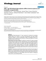
Fig. 100.1.2(A.2) Code Jurisdictional Limits for Piping — An Example of Steam Separator Type Forced Flow
Steam Generators With No Fixed Steam and Water Line
Turbine valve or Code
stop valve para. 122.1.7(A)
Superheater
Turbine
To equipment
Steam
separator
Convection
and radiant
section
Reheater
Water
collector
Start-up system
may vary to suit
boiler manufacturer
(if used)
Economizer
Recirculation pump
(if used)
(if used)
Para. 122.1.7(B)
(if used)
Boiler feed pump
Alternatives para. 122.1.7(B.9)
Administrative Jurisdiction and Technical Responsibility
Boiler Proper – The ASME Boiler and Pressure Vessel Code (ASME BPVC) has total
administrative jurisdiction and technical responsibility. Refer to ASME BPVC Section I Preamble.
Boiler External Piping and Joint (BEP) – The ASME BPVC has total administrative jurisdiction
(mandatory certification by stamping the Certification Mark with the appropriate Designator,
ASME Data Forms, and Authorized Inspection) of BEP. The ASME Section Committee B31.1 has
been assigned technical responsibility. Refer to ASME BPVC Section I Preamble, fifth, sixth,
and seventh paragraphs and ASME B31.1 Scope, para. 100.1.2(A). Applicable ASME B31.1 Editions
and Addenda are referenced in ASME BPVC Section I, PG-58.3.
Nonboiler External Piping and Joint (NBEP) – The ASME Code Committee for Pressure Piping,
B31, has total administrative and technical responsibility.
3
ASME B31.1-2016
Fig. 100.1.2(B.1) Code Jurisdictional Limits for Piping — Drum-Type Boilers
(16)
Vents and
instrumentation
122.6.2
Single installation
122.1.2
Multiple installation
Common header
Level indicators 122.1.6
Steam drum
Drain
Vent
Drain
Inlet header
(if used)
t
n
Ve
Soot blowers
Single installation
Superheater
Vent
122.1.7(D)
Hot reheat
Drain
Main steam
122.1.2
Soot blowers
Multiple installations
Common header
Reheater
Vent
122.1.7(D)
Cold reheat
Surface blow
Continuous
blow
Chemical feed
drum sample
122.1.4
Control device
122.1.6
Drain
Drain
Drain
t
n
Ve
Single boiler
Economizer
Single boiler
Boiler No. 1
Feedwater systems and
valving 122.1.3 & 122.1.7
122.1.4
122.1.5
Boiler No. 2
Water drum
Two or more
boilers fed from
a common source
Regulating valves
Blow-off
single and multiple
installations
Boiler No. 1
Boiler No. 2
Drain
Two or more
boilers fed
from a common
source
Administrative Jurisdiction and Technical Responsibility
Boiler Proper — The ASME Boiler and Pressure Vessel Code (ASME BPVC) has total administrative jurisdiction and
technical responsibility. Refer to ASME BPVC Section I Preamble.
Boiler External Piping and Joint (BEP) — The ASME BPVC has total administrative jurisdiction (mandatory
certification by stamping the Certification Mark with the appropriate Designator, ASME Data Forms, and Authorized
Inspection) of BEP. The ASME Section Committee B31.1 has been assigned technical responsibility. Refer to ASME
BPVC Section I Preamble and ASME B31.1 Scope, para. 100.1.2(A). Applicable ASME B31.1 Editions and Addenda
are referenced in ASME BPVC Section I, PG-58.3.
Nonboiler External Piping and Joint (NBEP) — The ASME Code Committee for Pressure Piping, B31, has total
administrative jurisdiction and technical responsibility.
4